Preparations
- Tighten the transparent belts (upper 3100TBU and lower 3100TBL)
- Install the 15 watt fluorescent tube (3100LAMP)
- Remove the lens cover
- Set the voltage selector at the proper position and check to see if the correct fuse is installed
Each of these procedures is discussed below.
Rear housing removal
The rear housing must be removed in order to adjust the belt tension and to install the fluorescent tube. Using the 5/32" (4 mm) hexagonal key provided, remove the four retaining screws (one at each end, one at the center front edge on top, and one at the center bottom edge at the rear). Lift the housing from the instrument.
Transparent belt tension adjustment
Perform the following steps to tighten the transparent belts.
- Loosen the large knurled knobs located on each sliding pulley bearing block.
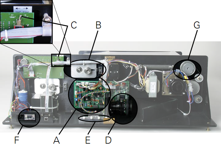
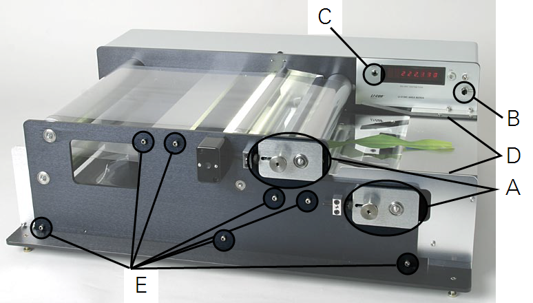
- Rear sliding bearing blocks are B in Figure 2‑1. Front sliding bearing blocks are A in Figure 2‑2.
- Coarse adjustment is performed by simultaneously sliding both bearing blocks for one pulley.
- The knurled knobs can be tightened sufficiently by rotating them with the thumb and index finger while holding tension on the bearing block with the remaining fingers of the same hand.
- Fine adjustments are performed by twisting the block adjustment screw to push the sliding bearing block.
- The knurled knobs located on the pulley bearing blocks must be loosened to allow block movement.
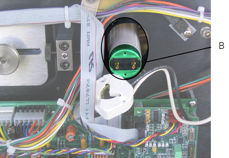
Fluorescent tube installation
Note that the fluorescent tube (part number 3100LAMP) may be enclosed inside the rear cover of the LI-3100C during shipping. Remove the rear cover to unpack and install the fluorescent tube.
Watch a video of this procedure at
licor.com/support/LI-3100C/videos.html
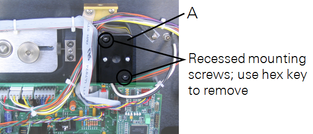
- Remove the rear tube connector housing by loosening the two recessed mounting screws.
- See Figure 2‑3.
- Hold the new tube vertically and gently tap it to cause any internal debris to collect at one end.
- Internal debris can cause spurious counting.
- Slide the tube into the exposed hole in the instrument rear plate.
- Rotate the tube as needed until it seats in the front connector. Twist the tube slightly until it snaps into place. You may need to twist in either direction, depending on the tube's initial position in the front connector.
- Mount the rear connector housing over the exposed tube end.
- Gently twist the connector while holding the tube at the back edge of the upper belt.
- The rotation should be about 1/4 turn.
Voltage selector operation and characteristics
The voltage selector is located in the power connector module (F in Figure 2‑1). The selector is inspected for proper voltage by sliding the clear plastic window to a position over the power connector. The visible number on the small printed circuit board located under the fuse indicates the selected voltage as follows:
- Either 100 or 120 V for 105-126 VAC operation.
- Either 220 or 240 V for 210-252 VAC operation.
Notice that the visible number is not the actual operating voltage. The instrument will not function on 100 VAC.
The voltage selector is changed by sliding the circuit board outward from its mount and repositioning it so that a different number is visible as appropriate to the available voltage.
The frequency usually changes from 60 to 50 Hz when the voltage is shifted from 120 to 240 VAC. This will change the instrument calibration approximately 0.5%. An instrument calibration should be performed after changing the voltage.
At locations with fluctuating main current frequency, calibration should be checked often during operation.
The proper fuse selection is:
- 105-126 V, use 1 amp fuse.
- 210-252 V, use 1/2 amp fuse.