Changing measurement resolution
The 1.0 mm2 resolution may be preferable where large samples are being measured, and the continuous buildup of debris on the belts causes excessive spurious counts.
Changing from 1.0 mm² to 0.1 mm² resolution
The procedures for the resolution change are outlined in the following steps.
- Disconnect the power.
- Remove the rear housing by removing the four retaining screws.
- Move the decimal selector switch to the 0.1 mm2 position (near the switch; C in Figure 2‑1). This switch is located at the top right corner (as viewed from the rear of the display circuit board.
- Loosen all four set screws on the outer camera pressure rail (E in Figure 2‑1).
- Align the red focus mark to the red lens index mark on the inner camera alignment rail (Figure 4‑1).
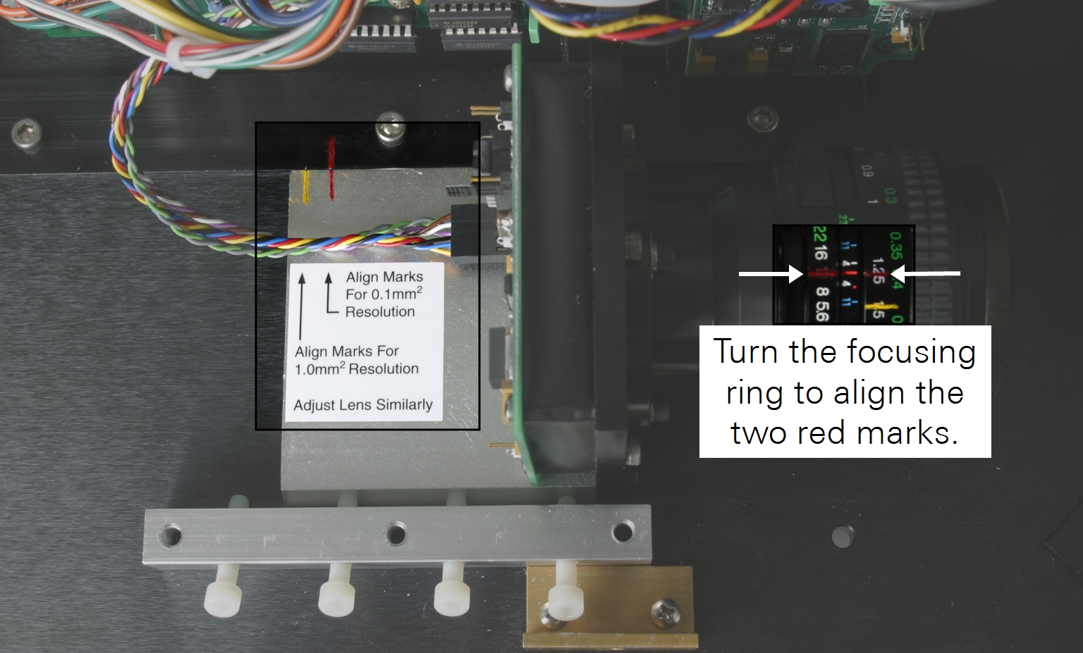
- Turn the lens focusing ring to align the two red marks.
- Lightly tighten the set screws.
- Be sure that the lens cover has been removed and that no other obstruction is in the optical path.
- Replace the rear housing.
Calibration should not be necessary; check the calibration if desired.
Changing from 0.1 mm² to 1.0 mm² resolution
The procedures for resolution change are outlined in the following steps.
- Disconnect the power.
- Remove the rear housing by removing the four retaining screws.
- Move the decimal selector switch to the 1.0 mm2 position (C in Figure 2‑1).
- Loosen all four set screws on the outer camera pressure rail (E in Figure 2‑1).
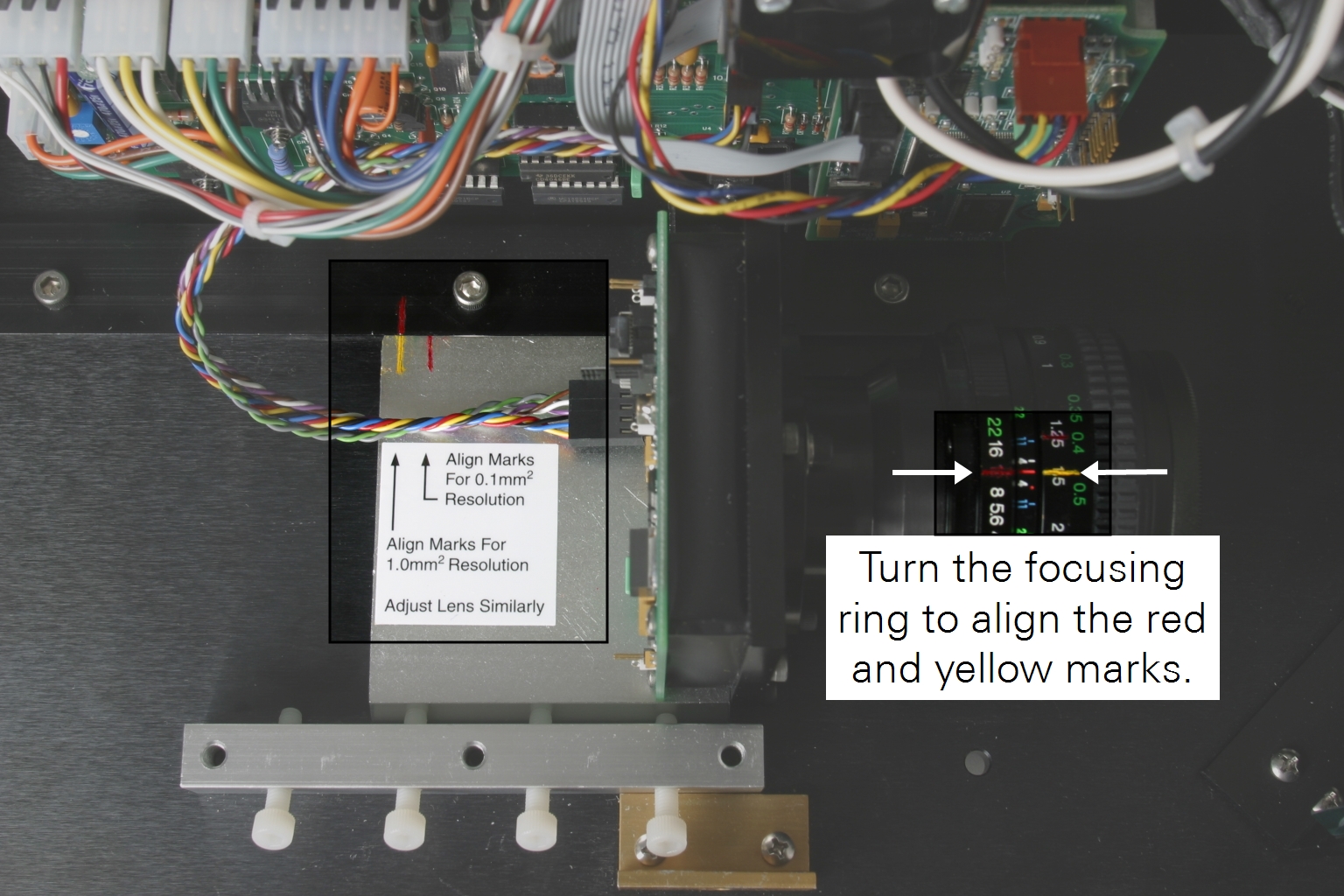
- Align the yellow mark to the red index mark (Figure 4‑2).
- Turn the lens focusing ring to align the red and yellow marks.
- Lightly tighten the set screws.
- Be sure the lens cover has been removed and that no other obstruction is in the optical path.
- Replace the rear housing.
Calibration should not be necessary; check the calibration if desired.