Mounting the LI-560
This section describes how to install the LI-560 and covers considerations for deployment.
Orientation
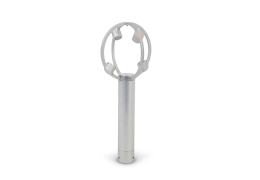
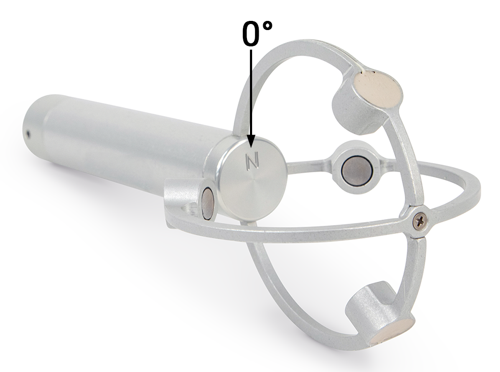
The LI-560 has a north indicator N on the cap at the top of the mounting post.
Airflow passing directly into the N will return zero degrees for the wind direction, regardless of the actual orientation of the LI-560. Adjustment of wind direction for orientations other than pointing to true North can be done in post processing of data.
Mounting the LI-560
The LI-560 can be mounted to a user-supplied pipe, a custom platform, or a tripod with the 560M adapter.
Pipe mount
The LI-560 has a circular connector to mount over a standard ½” DN15 Schedule 10 pipe or 22 mm OD/20 mm ID carbon fiber tube.
The pipe must be a thin wall type, as indicated by the Schedule 10 designation, to allow an inside diameter wide enough to let the mating cable connector pass through the pipe.
Before putting the LI-560 on the pipe, route the cable through the pipe. Then connect the cable connector to the base connector. Place the LI-560 over the pipe and tighten the three set screws to secure. Do not overtighten the set screws.

560M mounting adapter
The 560M is an optional mounting adapter for attaching the LI-560 to a custom platform. It features a brass ¼-20 threaded insert that is compatible with most camera tripods.

Tilt and level considerations
If you intend to use data from the accelerometer, either with a single anemometer or to compare with other anemometers, it should be calibrated in the environment in which it will be deployed.
The accelerometer in the LI-560 measures offsets from level. Because the mounting of the LI-560 affects the tilt, offsets are not set during manufacturing. Persistent offsets in the data could indicate that the calibration needs to be adjusted. Calibration can be initiated in the menu interface (see Calibration) or command-line interface (see levelcalibrate). See Level calibration for more details. The raw accelerometer outputs are also available.
Environmental considerations
Be mindful of environmental conditions that may affect the performance of the sensor. The LI-560 is designed for outdoor use, but some limitations apply.1 Protect the instrument from sustained rainfall and persistent high humidity (condensing conditions). If the device will sit outdoors unused for long periods, you can cover it to reduce the accumulation of dust, pollen, and other contaminants.
Ice and Snow
The LI-560 has no on-board heaters. The LI-560 is designed for outdoor use, however, if ice or snow accumulate on the transducers or within the LI-560, the acoustic pathways between transducers can be blocked. The LI-560 may not be the best choice for sustained use in wintery weather.
Not submersible
The LI-560 is not submersible in water.
Interference considerations
Be aware of these potential sources of interference as you plan your project and interpret data.
Other sonic anemometers
If using more than one anemometer, maintain at least one meter separation distance between the two devices to prevent ultrasonic interference. Two TriSonica anemometers that are close to each other may appear to work fine, but over time, the two clocks will come into phase with each other, leading to spikes in the measurements. Avoid the situation by maintaining at least one meter of separation.
Compact fluorescent lamps
Some compact florescent lamps (CFL) make ultrasonic noise that can interfere with the operation of a LI-560. Erroneous readings may result if the LI-560 is operated near compact florescent lamps. Turn off the CFL or move the sensor away from the CFL to reduce interference.
Wind tunnels and ultrasonic frequency
Ultrasonic anemometers operate by generating ultrasonic pulses and measuring the time of flight of those sound pulses between transducers. The time-of-flight measurements can be disturbed by external noise sources in or near the same frequency band used by the ultrasonic anemometer’s transducers. The LI-560 operates in the 60 KHz ultrasonic frequency range.
We have found that some wind tunnels generate ultrasonic noise that can cause erroneous readings from the anemometer. This is not an indication of failure of the anemometer but is a result of using the anemometer in an ultrasonically noisy environment.