Hardware configurations
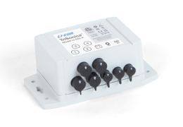
Each anemometer, GPS receiver, and radio connector on the circuit board has configuration options. These options let you change how the circuit board communicates with a device. Open the enclosure and remove the board to see the solder-configurable jumpers related to the configuration options.
Caution: To ensure the enclosure meets ingress standards after disassembly, confirm that the gasket is positioned correctly between the two halves, and then tighten the four screws. Double check the tightness of each screw before deploying outdoors.
Each jumper is in a white rectangle and is identified by an alpha-numeric code beneath it, with the solder pads located inside the white rectangle. The function of each connector can be changed by changing which solder pads are connected by a solder trace. To change the configuration of a connector, you will open a solder trace between to solder pads and close the solder trace between two other solder pads.
Warning: Changes to the jumpers should be carried out by a skilled electronics technician.
Configuring anemometer ports
Instrument ports 1 through 4 are for sonic anemometers. Each can be configured independently to record EIA232 or UART signals, as described next.
Instrument 1
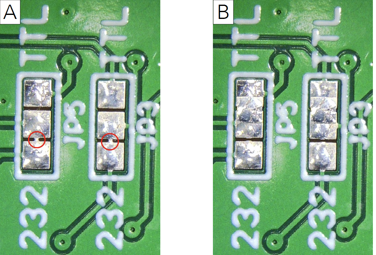
The jumpers JP5 and JP3 change the serial port configuration between EIA232 and UART signaling levels for instrument 1. The default is EIA232 (A in Figure 6‑1).
Instrument 2
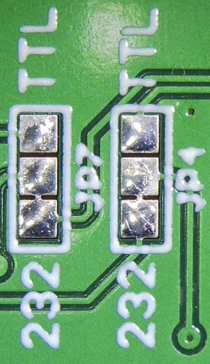
The jumpers JP7 and JP4 change the serial port configuration between EIA232 and UART signaling levels for instrument 2. The default is EIA232 (Figure 6‑2).
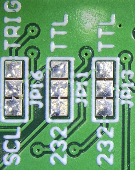
Instrument 3
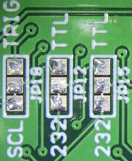
The jumpers for instrument 3 are labeled JP16, JP11, and JP13. JP16 selects the function of pin 5 of the INST 3 connector to be either a trigger signal or the SCL (I2C Clock). JP11 and JP13 change the serial port configuration between EIA232 and UART signaling levels. The defaults are SCL and EIA232 (Figure 6‑3).
Instrument 4
The jumpers for instrument 4 are JP18, JP12, and JP15. JP18 selects the function of pin 5 of the INST 4 connector to be either a trigger signal or the SCL (I2C Clock). JP12 and JP15 change the serial port configuration signaling levels. The defaults are SCL and EIA232 (Figure 6‑4).