
LCF Troubleshooting
LCF Control Panel
A convenient place to do troubleshooting on the LCF is from the LCF Control Panel (Home Menu|Diagnostics & Tests|LCF Control Panel), shown in Figure 27‑72.
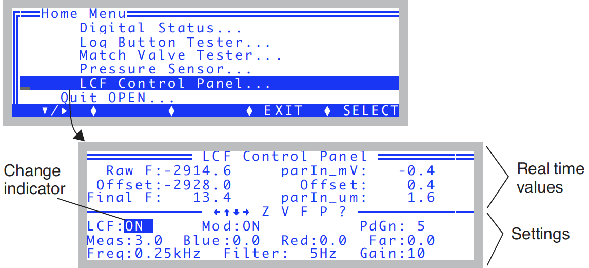
The top lines show real time values of fluorescence and the ParIn_μm values. The bottom three lines are the settings fields. The highlighted value can be changed by pressing ▲ or ▼. For the Meas, Blue, Red, and Far field, shift + ▲ or ▼ changes the settings by 0.1 instead of 1.0. Pressing Z will set the offset value so that Final F will be 0. This can only be done when Mod is ON, and Meas is set to 0. Pressing V will access the program View Factory Cal.
Raw F
The raw fluorescence reading of the LCF. This value will be between -5000 and +5000, and is the mV signal on analog input channel 20.
Offset
The offset value for zeroing the fluorescence signal. This is typically -2900 or so. This value is subtracted from the Raw F reading to yield the Final F value.
Final F
This is the value presented in New Measurements as F, the basic fluorescence signal. It typically ranges from 0 to 8000.
ParIn_mV
The mV signal of the LCF quantum sensor. This is analog input channel 23. It ranges from 0 to -5000 mV. (That is why both the red and blue calibration constants are < 0. See ParIn_μm.)
ParIn_μm
The PAR as measured by the LCF quantum sensor. The calibration factors used to convert parIn_mV to this value are stored in the LCF sensor head. To see these values, press V, and the “_View Factory Cal” program will be accessed.
LCF: ON/OFF
This control turns the LCF on and off. The LCF fan turns on and off with this control as well. If you want to interchange an LCF, use this control to turn it off before disconnecting; after reconnecting, use this control to turn it back on.
Mod: ON/OFF
This control turns the modulation on the measuring beam on and off. When off (and the measuring beam intensity set > 0), the two blue measuring LEDs will appear significantly brighter than when modulation is on.
PdGn: 1 or 5
The photodiode gain for the parIn_mv measurement. Normally, this is set to 5. During a flash, OPEN automatically sets it to 1 to prevent overranging the signal. When you toggle this back and forth, the parIn_mv and ParIn_μm values should change by about a factor of 5.
Meas: 0 - 10
This controls the intensity of the measuring beam. The higher this is, the brighter the two measuring LEDs will appear. If measuring a fluorescing sample, the values of FlrRaw and Final F will be proportional to this setting.
Blue: 0 - 10
The intensity of the blue actinic LEDs. At 10 (and with Red = 0), the ParIn_μm value should be 100 or more.
Red: 0 - 10
The intensity of the red actinic LEDs. Typically by 4 the ParIn_μm reading will be above 2000 μmol m-2 s-1. You can run it up to 10, but don’t leave it there for more than a few seconds. This isn’t the best way to test maximum output, as the output will decrease steadily as the LEDs heat up. Leaving the red LEDs at 10 for an extended period will shorten their useful life.
Far red: 0 - 10
The intensity of the far red LED. You can see it, although it looks a bit dim. At full output (10), the typical quantum flux is <10 μmol m-2 s-1. Freq: 0.25, 1, 10, 20 kHz Select the frequency of modulation of the measuring beam.
Filter: 0.5, 1, 5, 10, 20, 50, 100, 200 Hz
Select the bandwidth (averaging) for the raw fluorescence signal. The higher the number, the faster the response to changes, but at a price of increased noise.
Gain: 10, 20, 50, 100
The gain used for the raw fluorescence signal. 10 is normally used. At 20, the raw fluorescence signals will be about twice as large. So will the noise.
Basic Functionality Test
The LCF Control Panel program described above can be used for a simple functionality test.
- LCF ON/OFF
- Toggle the LCF on and off. When off, the fan should stop. When on, the fan should start.
- Mod ON/OFF
- With the LCF: ON, Mod: ON, and Meas: 3.0, the green MSR status LED should be on. Now look at the two red measuring LEDs in the LCF as you toggle Mod ON and OFF. The two LEDs should get bright when Mod is OFF, and be dimmer when Mod is ON. The green MSR status LED will remain on.
- Freq settings
- With Mod ON, cycle through the Freq settings. You should see the brightness on the two measuring LEDs change. The higher the frequency, the brighter the LEDs.
- Zero the fluorescence signal
- Turn Mod ON and set Meas to 0. The signal (“Final F”) should go to zero (+/- 4). Press Z to make it do that, if necessary.
- Check the fluorescence response
- With Meas on 3, Mod ON, Filter on 0.5, and Gain on 10, clamp the chamber onto the pink fluorescence “standard”1 in the LCF spares kit. The readings should be roughly 300 or 400. The peak to peak noise of the signal should be about 2 or 3. If there is no response to the standard, or to any leaf, then the fluorometer is not working.
- Check digital filtering
- Change the Filter to 200 (press down arrow to jump there from 0.5). The peak to peak noise will increase by a factor of 10. Set the filter back to 0.5.
- Blue Check
- Change Blue from 0 up to 2. Check to see that all three blue actinic LEDs in the LCF are on. Now increase it up to 10. The ParIn_μm value should be about 150 or 200. Turn them back to 0.
- Red Check
- Turn the Reds to 1 and see that they come on. (They will either be all on or all off.) Turn them off. (Warning: there’s nothing keeping you from turning the reds up to 10. They’ll be very bright and painful to view directly. Leaving them on that high for more than a few seconds will shorten their lifetime.)
- Far red check
- Turn the far red up to 10. Look and see that it is illuminated. Turn it off.