
System Console
Cleaning
Wipe with a soft cloth. Be careful not to scratch the display window.
Opening the Console
You will need to remove the cover to replace any of six different fuses, or to
replace the internal air filter (Balston).
To remove the console cover:
- Disconnect everything
- Disconnect all cables and hoses from the console and remove the batteries.
- Remove the screws
- Remove the eight screws (127-00007) (nine screws on early units) on each side of the LI-6400 console case with a Phillips head screwdriver.
- Drop the cover
- Grip the carrying handle and lift the card cage out of the lower shell.
Internal Air Filter Replacement
The air filter should be replaced annually; more frequently in dirty environments.
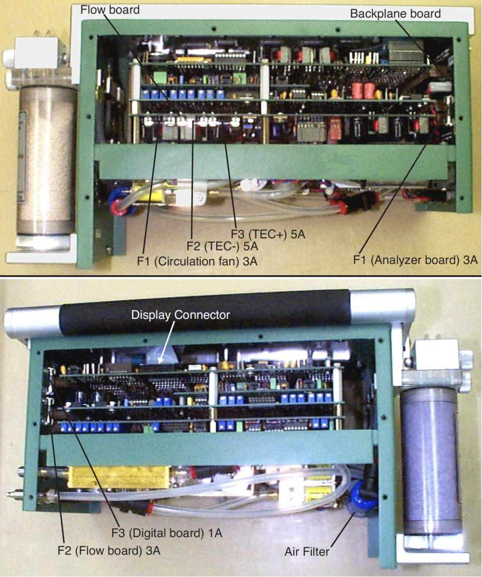
The filter is located inside the LI-6400 (Figure 19‑9). Disassemble the console as described above .
Note: Console serial numbers PSC101-160 that do not have the 6400-01 CO2 injector option will have two Balston air filters.
Before installing, blow through a new filter in the direction of the white flow arrow to remove any fibers or other debris that may be loose inside.
The filter is attached to the air line with a quick connector. The old filter can be removed by compressing the red ring into the quick connector body and pulling the connector off of the filter. Leave the connector attached to the hose, as repeated removal from the hoses may result in a leak. The filter may also be removed by inserting a pair of long-nose pliers between the coupling and the filter; gently pry the two apart, using the filter body as a fulcrum.
Install the filter with the white directional arrow aimed in the direction of the air flow; air flows to the filter from the desiccant tube. (See Figure 20‑19.)
Spare filters can be ordered from LI-COR under part number 300-01961 (one each).
Replacing the Fuses
Remove the card cage as described above. There are six fuses located on two different circuit boards; there are three fuses on both the backplane board and the flow board (Figure 19‑9). Table 19‑1 lists the replacement fuses that should be used. Extra fuses can be found in the spare parts kit.
When installing a fuse, be sure to exactly center it in the holder. If you don’t, one end of the fuse will hit the retaining part of the clip and spread that clip too wide, eliminating contact once the fuse is fully inserted.
Removing the PC Boards
This is certainly not part of normal maintenance, but we include these instructions here for reference purposes, should you ever have to perform this operation as directed by some sadistic LI-COR technician.
- Power the LI-6400 off, and disconnect all cables and batteries
- Remove the console bottom shell
- See Opening the Console.
- Unplug the display and keyboard connectors
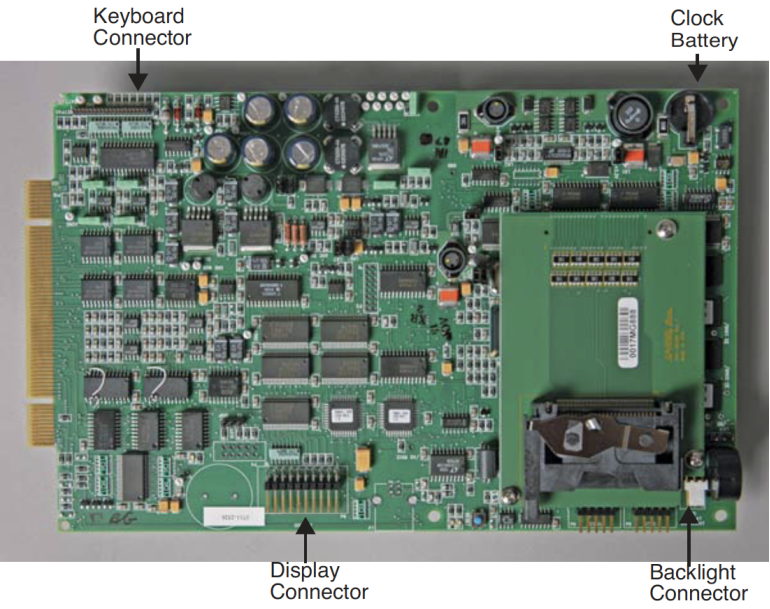
- Unplug the keyboard connector by carefully lifting it up from the pins on which it sits (A in Figure 19‑10). Then, unplug the display connector on the other side of the console (B). Finally, if there is one, unplug the back light connector (C).
-
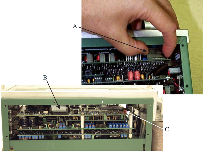
Figure 19‑10. The keyboard (A), display (B), and backlight (C) connectors. - Turn the console upside down and disconnect all flow board connectors
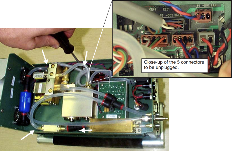
- All of the connectors in question go through a square hole to the flow board (Figure 19‑11).
- Remove the board assembly retaining screws
- There are four shown by the white arrows in Figure 19‑11.
- Unplug the board assembly
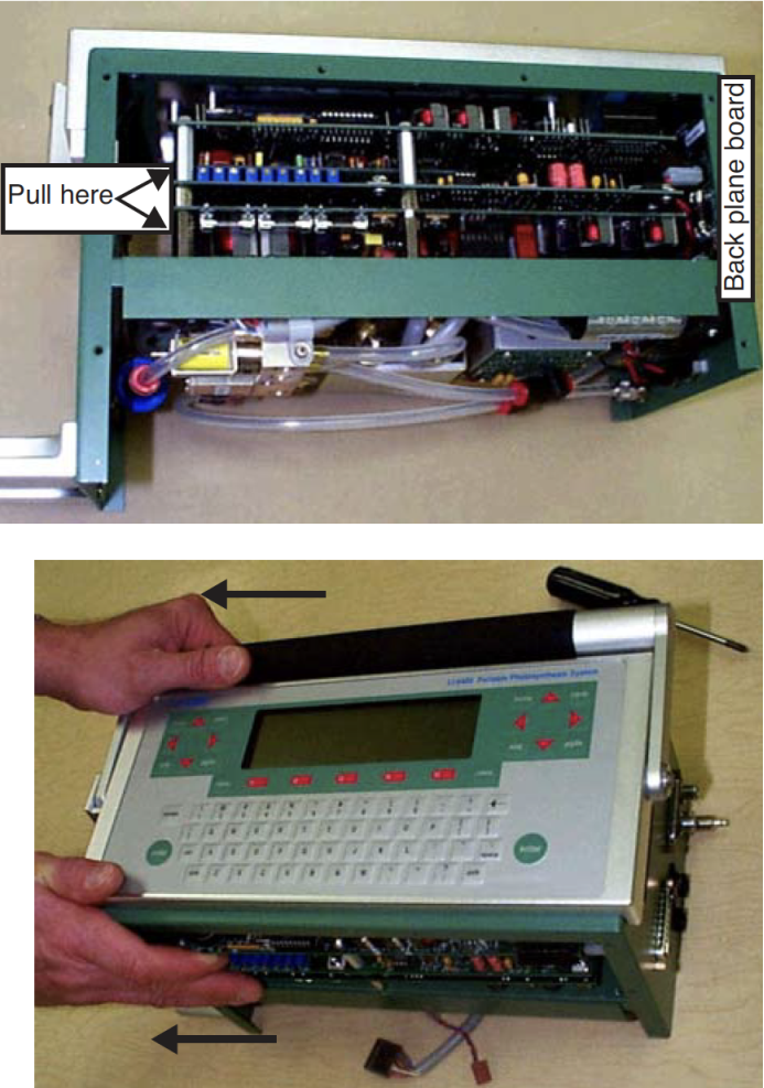
- All of the boards in the assembly connect to the back plane board at the right end of the console. Unplug these boards by hooking your fingers on the standoffs on the back of the assembly and pulling (and rocking back and forth gently) the assembly out of the connectors (Figure 19‑12).
- Slide the board assembly out of the console
- Be careful that the display and keyboard cable and connectors don’t snag on the boards as you slide them out of the console.
Re-installing the PC Boards
- Slide the board assembly back into the console
- Be careful not to snag the keyboard and display connectors and cables.
- Re-connect the keyboard, display, and backlight (if present) connectors
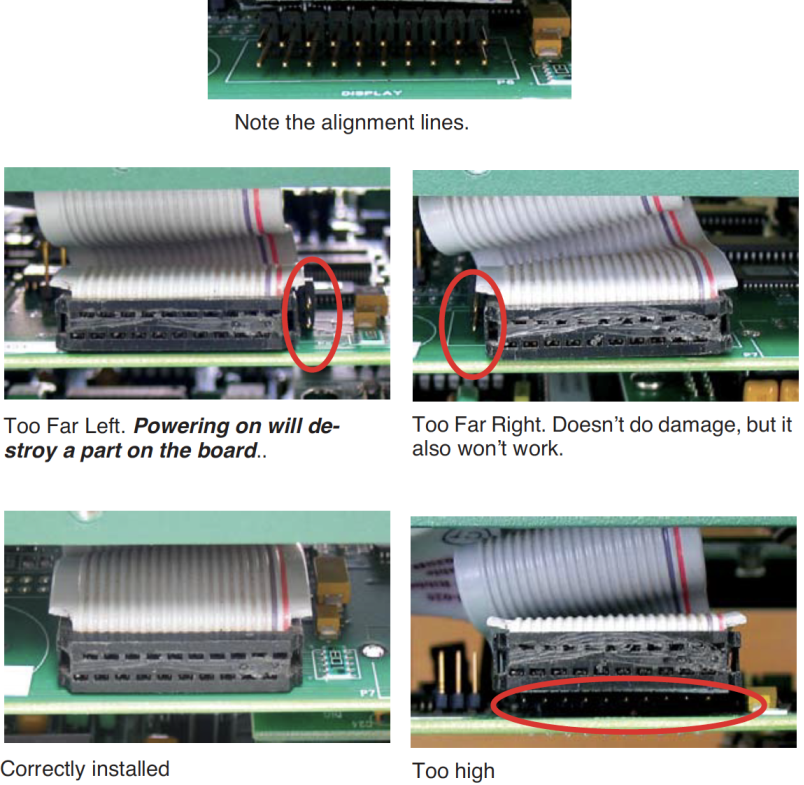
- Make sure the connectors are centered, especially the display connector (Figure 19‑14). If you are off a pin to the left or right, you can do damage when you turn on the power.
- Re-seat the board assembly
- Line up the edge connectors of the three boards, and push them into the back plane board by pushing on the standoffs between the boards.
- Install the retaining screws
- Turn the console over, and re-install the four screws. The board assembly has to be fully seated before the screw holes line up.
- Reconnect the flow board connectors
- Refer to Figure 19‑15. Note the labels on the flow board by each connector.
Real Time Clock
The real time clock is powered from the main battery while the console is turned on. When the console is powered off, the clock is run from a 3V lithium battery. The battery should operate for many years.
When the voltage on the battery drops to 2.7V, the battery (LI-COR part number 442-03791) should be replaced. See Real Time Clock Problems on page 20-5 for instructions about measuring and replacing the battery.