Finding Leaks
Leaks will get your attention by causing unstable CO2 readings that you might first suspect are IRGA problems.
Sensor head or console?
If the reference cell concentration appears to be stable, but the sample cell concentration is unstable, it suggests a leak somewhere in the sensor head. If both are unstable, it suggests a leak in the console.
Sensor Head Leaks
If the reference is stable, try a leak test on the tightly closed chamber: Exhale on and around the leaf chamber, and see if the sample CO2 responds. You should not see more than a 1 or 2 ppm rise in CO2 in a properly sealed chamber. There will always be some effect of breathing near the gaskets due to CO2 diffusion through the gasket material, but it is delayed and fairly small. If you see rises in excess of 5 or 10 μmol mol-1, you have leak that should be fixed. To isolate the leak, you might try blowing through a small straw at selected places. Hints:
- O-rings
- Make sure that all 6 O-rings are in place (between the chamber halves and the IRGA manifold), clean, and lightly lubricated.
- Cap screws
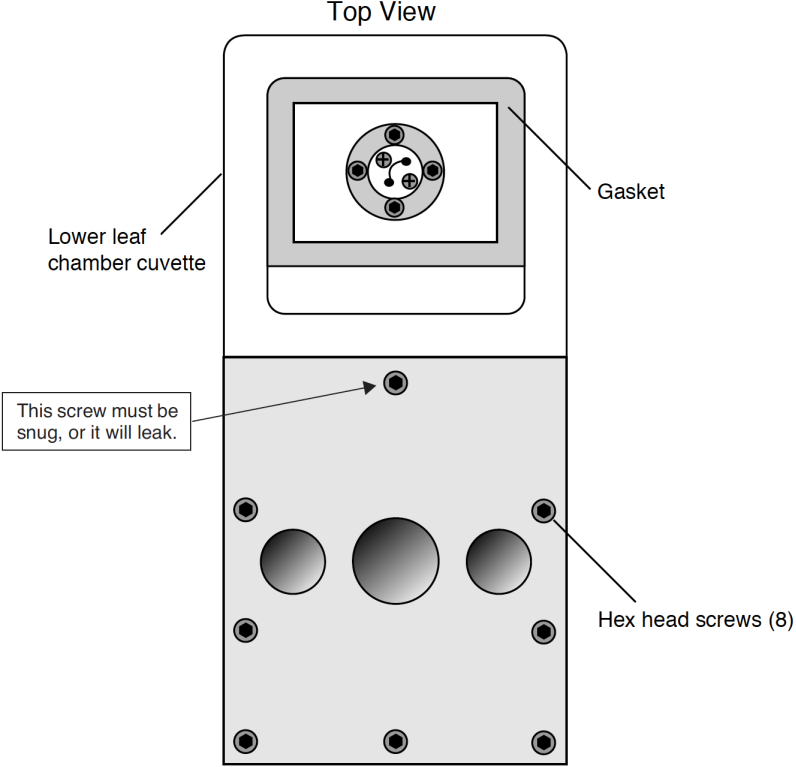
- Another possible leak source is the screw indicated in Figure 20‑18.
- Gaskets
- Are they centered? Is there a tiny wrinkle beneath that acts like a channel? Don’t forget the 3-hole rear gasket.
Hose Leaks
It’s not common, but once in a while we find leaks in a hose connector, due to the O-ring on the connector being dried and worn or cracked. Lubricate with silicon grease.
Console Leaks
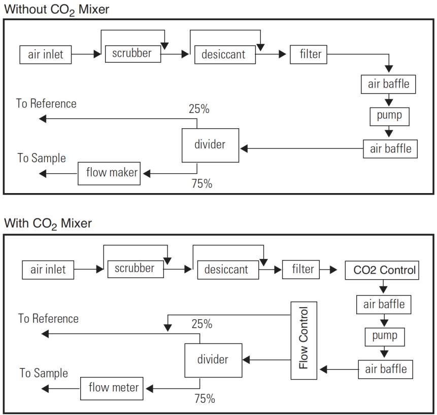
It is helpful to have a simple flow schematic (Figure 20‑19) in mind when tracking down a leak in the console. Any leak on the vacuum side of the pump will cause ambient air to be sucked into the system, so breathing on the chemical tubes, or into the case, will cause rapid rises in CO2 a few seconds later in both IRGAs. (This test is best done with the CO2 scrub ON, so that any of your breath that makes it into the normal air inlet will be scrubbed).
Chemical Tubes
The chemical tubes are common sources of leaks, and leak-like behavior.
- Bad Soda Lime
- As soda lime wears out, it begins letting some ambient CO2 into the system.
- Orientation
- If the console sitting on its side, rather than sitting upright, a gap can occur along the length of the chemical tube at the top, creating a channel with reduced CO2 removal.
- The Air Passage O-rings
- There is a small O-ring around each air passage tube to the console (Figure 2‑1). Are they there? Are they clean and lightly lubricated? Are the chemical tubes fully seated against the console? Don’t overtighten the attachment screw, or you’ll never get it back off without tools. Lightly snug is sufficient.
- The End Cap O-rings
- There is a large O-ring on each end cap that should be compressed slightly when the end cap is tightened on. If there is a gap, it’s probably because the threads are dirty. Clean the threads with water if necessary, and keep them clean each time you change chemicals. See Cleaning The End Cap Threads.
Hose Barbs
Internally, there are a number of single flute hose barbs; visually inspect all hose barbs and check for tightness. Although the tubing might rotate freely1 on the hose barb flute, the hose barb itself must be threaded tightly into its threaded mounting hole. If you can't turn a hose barb with your fingers, then it is probably tight enough to not leak. Hose barbs can be tightened with a 1/4 inch end wrench or (in a pinch) needle nose pliers. They have rubber gaskets, so if they physically touch the surface they screw into, that might be tight enough. Be careful not to overtighten; hose barbs can break. Note that there are also four hose barbs on the block to which the chemical tubes are attached.
Quick Connectors
Inside the quick connector is a rubber seal, similar to an O-ring. When a hose is inserted into a quick connector, it pushes in rather easily until encountering the internal clamping device; it must then be pushed an additional 0.25 inch (0.5 cm) to make contact with the rubber seal. Variations in the outside diameter of the Bev-a-line tubing can make the insertion of the tubing into the quick connectors difficult; in such cases, improperly inserted tubing may work loose and cause a leak. Hint: Wet the end of the tubing before insertion. The red collet on the quick connector is for hose removal: press the collet in towards the center of the connector before pulling on the hose to remove it. If you can easily pull a hose out of a quick connector without depressing the red collet, it means that the hose was not inserted far enough. The clamp ring leaves a mark on the end of the hose; if this mark is 1/4” from the end, the hose was inserted correctly.
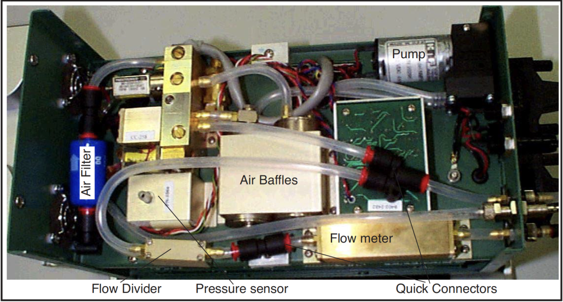
Air Baffles
One of the connections to one of the baffles has a 90° silver elbow fitting and a hose barb. There is an internal O-ring in the silver elbow between the body of the elbow and the air baffle, and another on the other side of the body of the elbow, under the part of the elbow that looks like a nut.
Pump
Make sure there is a good seal on the inlet hose barb of the pump. Inside the pump is a diaphragm and two flapper valves, each sealed with an O-ring. The replacement/repair kit for the pump is part number, 6400-907. If you disassemble the pump, scratch a line down one side so that it can be reassembled in the correct orientation.
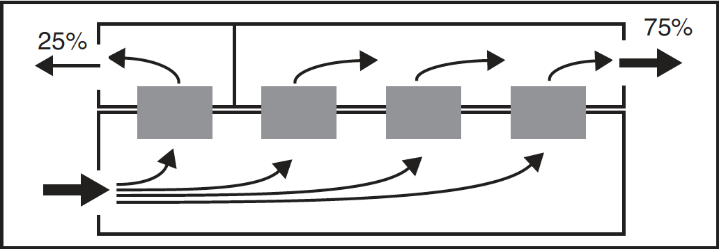
Flow Divider
Inside the body of the divider (Figure 20‑21) are four flow restrictors through which all the flow passes in parallel. Check the divider assembly screws for tightness. Be careful, as they are small (2-56 thread) and can break. If you disassemble the divider to check the 8 internal O-rings (2 for each flow restrictor), put a pencil mark on the outside of the two halves so that it can be reassembled correctly.