
Assembling the LI-6400XT
This chapter guides you through the assembly and preparations necessary to operate the LI-6400.
Preparations
This section explains how to prepare the console and sensor head for operation.
The CO2 Scrub and Desiccant Tubes
The CO2 scrub and desiccant tubes can remain attached to the console at all times, except when changing chemicals. Figure 2‑1 shows the position of these tubes.
Caution: Never unscrew the top cap while a tube is full of chemicals. To change the chemical, grasp the tube barrel (not the top cap) and unscrew the bottom cap. If the top cap is unscrewed with chemicals inside, damage to the air mufflers will occur.
Remove the bottom cap of the CO2 scrub tube, and fill the tube with soda lime (in the spares kit) to within 1 cm of the tube’s end. Replace the bottom cap and attach the tube to the console using the lower of the two knurled knobs.
Follow the same procedure with the desiccant tube. Indicating Drierite desiccant is provided in the spares kit.
Keep the threads on the end cap and barrel clean
Do not over-tighten the attachment screws (Figure 2‑1). Slightly snug (finger power only - never pliers) is sufficient. The O-rings do the sealing.
Complete information on maintenance and service of the chemical tubes is found on Chemical Tubes.

Cables And Hoses
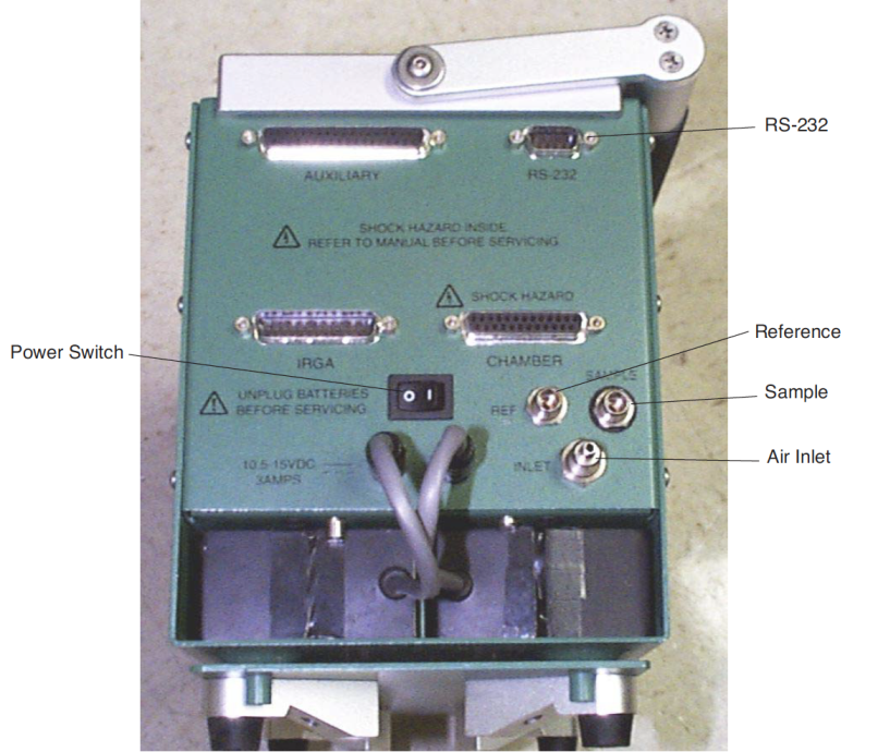
Air inlet and outlet ports and electrical connectors are located on the right side (end) of the console (Figure 2‑2).
Electrical Connectors
Plug the female 25-pin connector into the receptacle labeled IRGA, and the male 25-pin connector into the receptacle labeled CHAMBER. These connectors are gender specific, and cannot be interchanged. Tighten (slightly) the screws on the connectors, but be careful: these screws can break off if tightened too much. See Replacing Connector Screws.
Air Inlet
The port labeled INLET is located to the right of the ON/OFF switch. This is the intake through which the pump draws in the air that flows through the system.
If your system does not have a CO2 injector, attach tubing from a buffer volume to the INLET port. The buffer volume can be as simple as a clean, dry 2-liter plastic soft drink bottle. The larger the volume, the better. For more details, see Air Supply Considerations.
Air Outlets
The two sections of Bev-a-line tubing attached to the sensor head must be connected to the console air outlet ports. One of the tubes has a black band near the end of the hose. Attach this hose to the SAMPLE port of the console. Attach the other hose to the REF port.
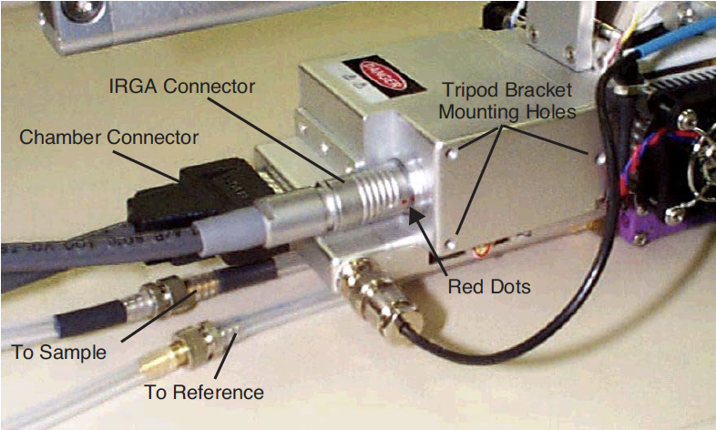
Connecting the Chamber / IRGA
The sensor head/IRGA end of the electrical cables attach as shown in Figure 2‑3. Be careful not to overtighten the screws on the 26-pin D-connector. To plug in the round connector, first line up the red dots, then push the connector all the way in until the red dots meet and there is a click.
Interchanging IRGAs? Don’t.
If you have more than one LI-6400 at your disposal, can you interchange the IRGA/chambers? The simple answer is (probably) no; they are not designed to do it. Each LI-6400 console is adjusted at the factory for a particular head. If you mismatch them, you may not able to zero the IRGAs.
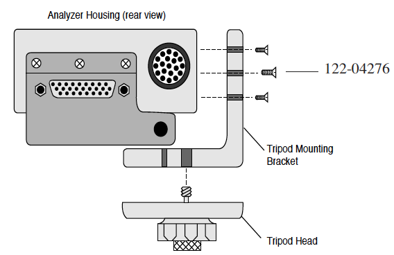
Using a Tripod
A mounting bracket is included in the spare parts kit for mounting the sensor head on a tripod. A tripod is a virtual requirement when making long-term measurements in the absence of cooperative graduate students. The three screws included with the mounting bracket are threaded into holes on the right side of the analyzer housing on the sensor head (Figure 2‑4). The tripod mounting bracket is threaded for use with standard 3/8-16 and 1/4-20 tripod heads.
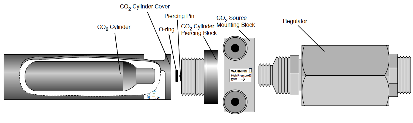
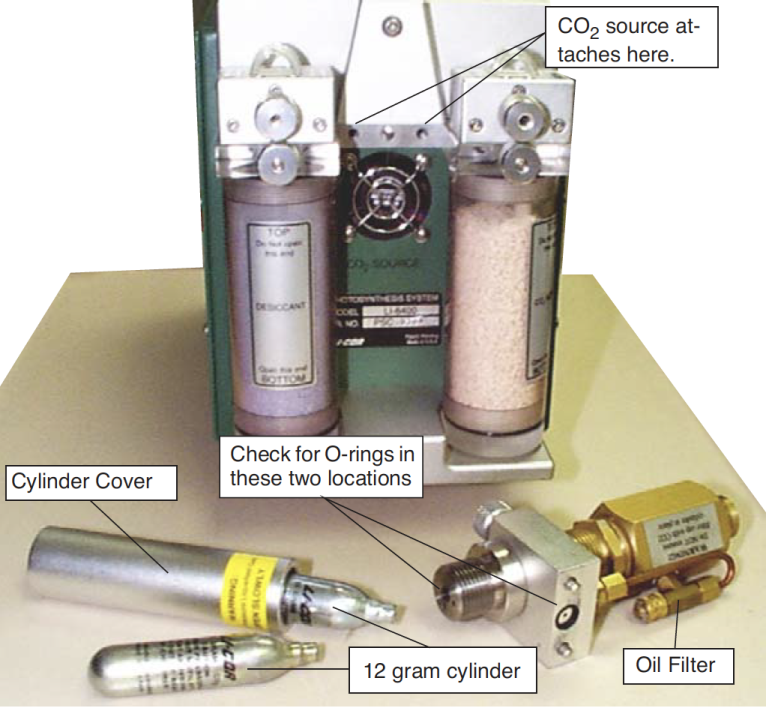
6400-01 CO2 Injector Installation
The optional 6400-01 CO2 Injector consists of a controller that is factory installed within the LI-6400 console, and an external part that attaches between the chemical tubes on the end of the console. This external part can be either
- the 9964-026 Source Assembly which uses 12 gram CO2 cartridges (described below), or
- the 9964-033 Tank Connector Block for using a tank of pure CO2 with a regulator (see . Location of external CO2 source assembly.).
Caution: CO2 cylinders contain 12 grams of high pressure liquefied CO2. Follow the handling precautions on the cylinder and cylinder cover carefully.
Note: 12 gram CO2 cartridges last about 8 hours from the time they are pierced, regardless of whether the system is in use or not. However, every once in a while - say, every 100 or 200 cylinders - you might encounter one that provides considerably less, such as only 1 or 2 hours.
Using CO2 Cartridges
To install the 9964-026 Source Assembly
- Attach the assembly block. Is the O-ring present?
- Make sure that the O-ring seal on the mounting block is properly seated. Tighten the two knurled knobs on the mounting block to secure the assembly to the console.
- Unscrew the CO2 cylinder cover.
- Install a new O-ring in the groove around the piercing block.
- Use your finger to press the O-ring into the groove (Figure 2‑7). If the O-ring is not in place when the CO2 cartridge is pierced, gas will rapidly vent out a hole on the underside of the mounting block.
-

Figure 2‑7. Top view of piercing block showing the O-ring location. - Important Note: Although the O-ring may perform properly for several cylinders, we recommend that it be replaced with each new cylinder. After being subjected to several high pressure cycles the O-ring weakens and becomes perforated, and easily tears or splits. If the O-ring is slightly torn or perforated, gas slowly leaks through the vent hole shortening the life of the cylinder. If the O-ring is split, gas rapidly vents until the cylinder is empty.
- Check the oil filter (every 3 or 4 cylinders)
- It’s actually a cigarette filter that is located in the “T” fitting on the rear of the source assembly (Figure 2‑6). It’s a good idea to unscrew the cap (before you install the cylinder!) and look down in at the end of the filter to check for any oil accumulating on the white filter material. If the filter is getting discolored, change the filter. See Servicing the External CO2 Source Assembly for more details. (With LI-COR cylinders, the filter should last for 25 cylinders. We have encountered other cylinders, however, that contain much more oil, notably Copperhead™ and Curtis™ brands, so beware.)
- Place a new CO2 cylinder into the cylinder cover
- The cylinder goes in large end first, although one of our engineers accidentally got one to work the other way around.1
-
Caution: Use only the proper size 12 gram cartridges.
- Screw the cylinder cover onto the piercing block.
- You may feel some resistance as the piercing pin contacts the cylinder. A short burst of venting CO2 may occur as the cylinder is pierced; the leak is minimal if you continue to quickly tighten the cylinder cover. Tighten the cover until snug; there’s no need to overtighten.
Using other sizes
The mixer cap is designed for a 12g CO2 cylinder, which is 83 mm in length. You can also use a shorter cylinder, such as the 8g ones readily available in Europe, by inserting a spacer into the cylinder cap. The spacer’s length should be such that the cylinder plus the spacer is 83mm (+/- 2 mm).
External CO2 Tanks
The Tank Connector Block replaces the 6400-01 External CO2 Source Assembly, and is useful in situations where CO2 tanks or other high volume supplies are available.
The tank connector block is designed for use at pressures between 180 and 220 PSIG (lbs in-2 gauge pressure) of CO2. Use a regulator, and do not exceed 250 PSIG CO2, as the pressure relief valve may vent your source.
The Tank Connector Block uses a 1/8” male NPT to 1/8” tubing fitting. This fitting has a flow restrictor installed (10 cm3 min-1). Do not remove this fitting. A 1/8” to 4 mm compression union is also provided for users who may be unable to obtain 1/8” copper tubing. Directions for installing the Tank Connector Block to a CO2 source using 4 mm copper tubing are given in Installation Using 4 mm Copper Tubing.
To install the 9964-033 Assembly
- Mount the CO2 Tank Connector Block
- Use the two knurled knobs to mount the block between the CO2 and H2O scrub tubes. Make sure that the O-ring seal on the back of the block is properly seated.
- Insert copper tubing
- Insert the 1/8” copper tubing between the 1/8” connector nut and the ferrule (Figure 2‑8).
-
Caution: Note the orientation of the ferrule. One of the tapered ends of the ferrule is longer than the other; the long end must be oriented toward the connector on the mounting block. When the nut is tightened onto the connector, the ferrule will be permanently crimped to the copper tubing, and you will not be able to remove it.
- Tighten the nut until snug, plus 3/4 of a turn.
- Connect your CO2 source.
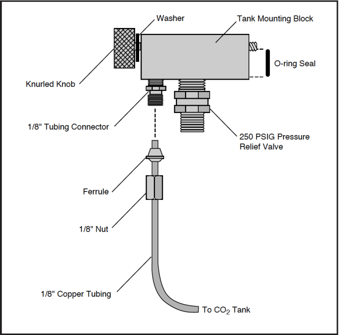
The other end of the copper tubing connects to your CO2 source. Adjust your regulator pressure to between 180 and 220 PSIG.
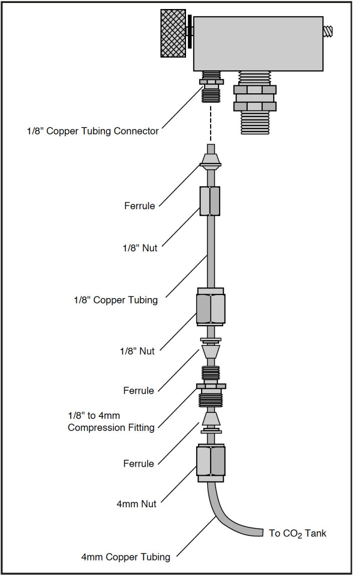
Installation Using 4 mm Copper Tubing
If you are unable to obtain 1/8” copper tubing, you can connect the Tank Connector Block to a CO2 source using 4mm tubing and the compression fitting (LI-COR part #300-04439) included with the Tank Connector Block.
- Install the Tank Connector Block and copper tubing
- This is described in steps 1-4 above.
- Connect the 1/8” and 4 mm tubing
- Use the 1/8” to 4 mm compression fitting to connect the two pieces of tubing (Figure 2‑9). Be sure to orient the ferrules correctly; the narrow tapered end of each ferrule must be oriented toward the compression fitting. Tighten the nuts on the compression fitting until snug, plus 1 1/4 turn.
- Connect the 4mm tubing to your CO2 source
- Adjust the regulator’s pressure to between 180 and 220 PSIG.
External Quantum Sensor Installation
The external quantum sensor is held in its mounting bracket with a small set screw (turned with a 0.050” hex key provided in the spares kit). The BNC connector plugs in at the rear of the chamber.
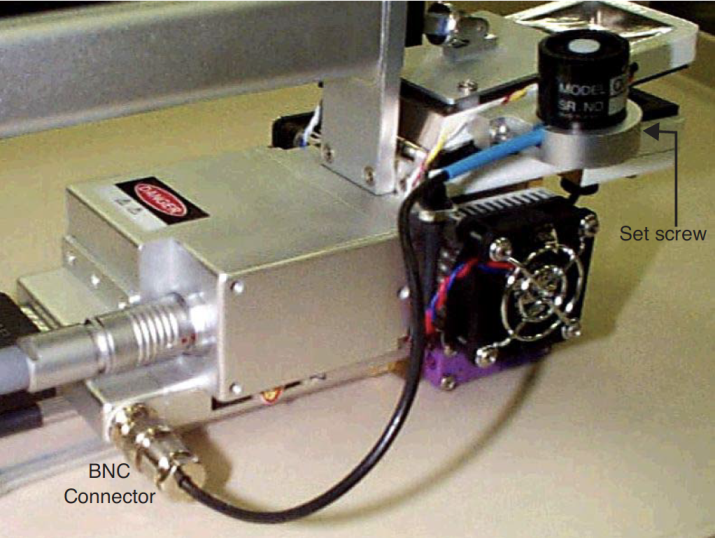
If the LI-6400 was shipped from the factory with an external quantum sensor, its calibration factor will have already been entered into the instrument. Otherwise, you will have to do this. See View / Edit Accessories.
Attaching the LED Light Source
The optional 6400-02 or -02B LED Light Source is mounted to the sensor head by removing the upper half of the leaf chamber and replacing it with the lamp assembly. Follow these steps to install the lamp:
- Remove the tripod mounting bracket
- This is necessary to access the connector for the in-chamber PAR sensor.
- Disconnect the light sensor
- Pull the connector straight out (don’t wiggle side to side) with a pair of long nose pliers (or your fingernails) gripping the connector (Figure 2‑11).
-
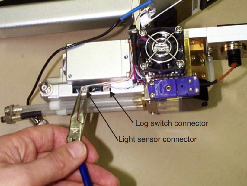
Figure 2‑11. Disconnecting the in-chamber PAR sensor connector. - Or, just grasp both wires with your fingers and pull straight out. The wires will bring the connector with it.
- Remove the top leaf chamber
- Use the 3/32” hex key provided in the spare parts kit to remove the two long screws that hold the chamber top in place (Figure 2‑12).
-
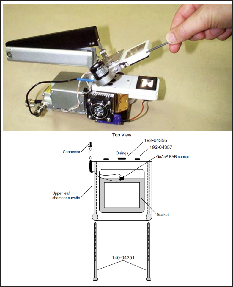
Figure 2‑12. The top and bottom chamber halves are held on with two hex head bolts. Use the 3/32 inch hex key to loosen and tighten them. - Install the O-rings
- Ensure that there are O-rings in the air passage holes.
- Install the lamp assembly
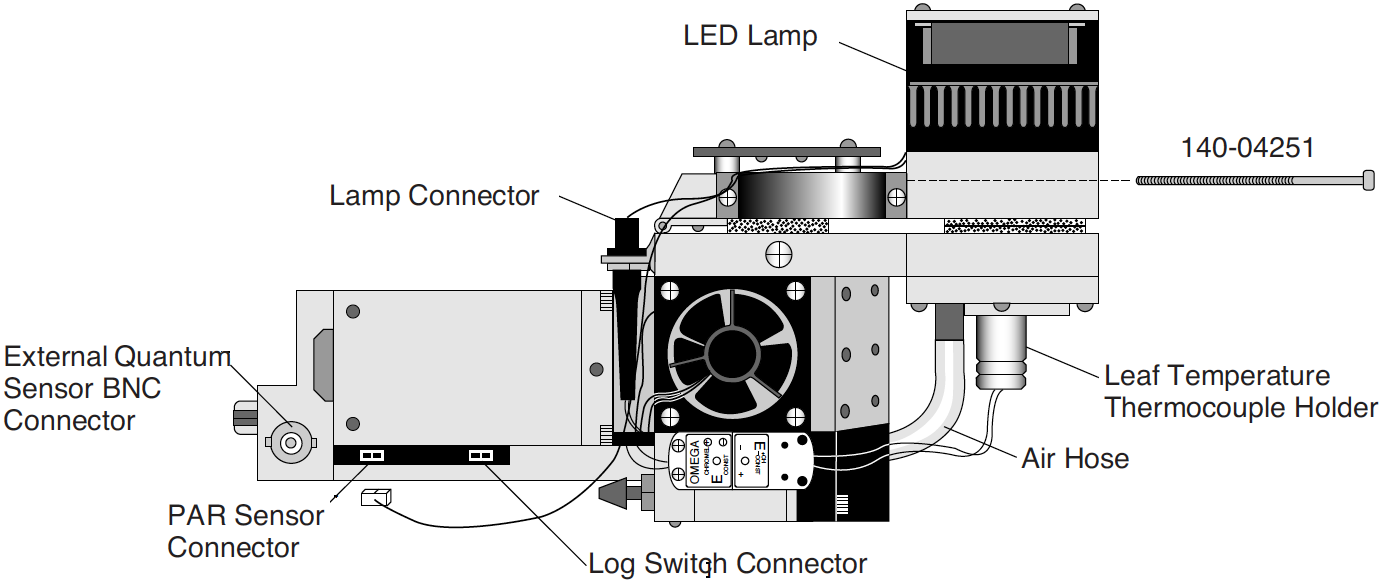
- Attach the lamp connector and PAR sensor connector as shown in Figure 2‑13. Ensure that the PAR sensor is attached to the connector near the rear of the analyzer housing, not to the log switch connector.
If the LED source was purchased with the LI-6400, its calibration factor will have been installed in the console. Otherwise, you will have to do this. See Example: 6400-02B LED Source on page 16-4 in the instruction manual for how to do this.
6400-40 Leaf Chamber Fluorometer
Installation and operation are described in Leaf Chamber Fluorometer.
Powering the LI-6400
LI-6020 Battery Charger
The LI-6400 cannot be operated from mains power alone using this battery charger. (For independent mains power operation, see 6400-70 AC Module.) It can, however, be operated with the charger and a single 6400-03 Rechargeable Battery. To use the LI-6020, plug a fully charged 6400-03 battery into one of the LI-6400 battery jacks, and plug the LI-6020 into the other jack using the 9960-062 cable (in spares kit).
Note: This will not provide indefinite operation. The battery will slowly discharge, and eventually need to be swapped. (Procedure to swap: Disconnect the plug from the charger, plug in a fresh battery, then disconnect the old battery and reconnect the plug from the charger.)
6400-03 Batteries
Two battery jacks are located beneath the ON/OFF switch. Insert two 6400-03 batteries into the battery compartment and connect both batteries. The 6200B batteries used with other LI-COR instruments can also be used, but with less convenience since they will not fit into the battery compartment of the LI-6400.
The 6400-03 batteries have a capacity of approximately 3 Amp-hours each. The LI-6020 Battery Charger produces about 1.5A. The LI-6400, on average, draws 1.5A; therefore, if the LI-6400 is drawing 1.5A, the LI-6020 used with a 6400-03 will power the LI-6400 indefinitely. At maximum draw (with LED light source on, running the coolers, etc.), the LI-6400 will use about 3A. Without the light source, it will draw about 2A. Table 2‑1 shows the approximate battery life when the LI-6400 is used with two 6400-03 batteries or with the LI-6020 Battery Charger and one 6400-03.
- Two batteries are better than one
- You will get better battery life when they are used in pairs.
- At least one battery is required
- You cannot run the system using only the LI-6020 charger.
- You are warned when the batteries are low
- The system will beep regularly when the batteries are low, and there are display indicators as well (see Low Battery Warning on page 5-18 in the manual). One low battery can be removed and replaced with a fresh one while the system continues to run without interruption. Immediately replace the second low battery with a freshly charged battery to ensure maximum operation time.
Shooting yourself in the foot…
When you are swapping batteries on a running, data-collecting instrument, be careful not to bump the on/off switch with your thumb as you unplug a battery. It’s easy to do (I speak from experience), and it quickly brings your measurements to an abrupt halt.
Note that you can also power the LI-6400 using any 12 volt battery with sufficient capacity; a car battery, for example, will run the system for 24 to 48 hours before recharging is necessary.
Other Batteries
You can power the LI-6400 with any 12 V battery (car, marine, etc.) that has at least a 1.5 Amp-hour capacity. To connect an alternative battery to the console, you’ll need a 318-02031 connector (the kind that is on the 6400-03 battery). One simple way to get this connector already attached to a cable is to remove it from a dead 6400-03 battery. Alternatively, you can order these connectors by themselves, or else order part number 9960-120, which is this connector attached to 10 feet of cable, or else obtain a 9960-062 (the cable that runs between the console and an LI-6020 charger), and cut it in half to get two short (2.5 ft.) versions of a 9960-120.
The 6400-03 batteries are protected with a 10 Amp automotive fuse (see Replacing the Battery Fuse). You might wish to do the same with your alternative battery.
6400-70 AC Module
This optional accessory allows the LI-6400 to be powered from mains power. It consists of a transformer, and a battery-shaped box that can fit in the console (Figure 2‑14).
Notes on using the 6400-70 AC Module
- A battery is not required
- The module will power the LI-6400 by itself. However, plugging a battery into the module will provide 1 or 2 hours continued operation in case of mains power failure.
- Use both plugs - most of the time
- The AC module has two plugs that go into the console’s battery connectors. For normal operations, plug both of them in.
- Hot swapping
- You can switch from AC operation to battery operation by unplugging one of the module’s plugs from the console, and replacing it with a fresh battery. Then disconnect the other plug, and replace it with second battery if you wish. Reverse the process to switch from battery to AC operation.
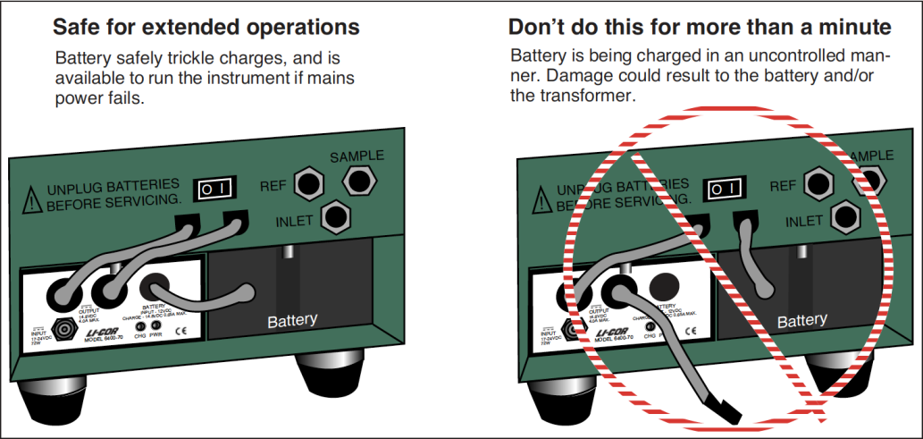
Either way, observe the caution in Figure 2‑15.
Important safety notice
To minimize shock hazard:
The 6400-70 AC Module MUST be connected to an electrical ground through a three-conductor power cable, with the third wire firmly connected to an electrical ground (safety ground) at the power outlet.
Any interruption of the protective (grounding) conductor or disconnection of the protective earth terminal may result in a potential shock hazard at the LI-6400 instrument chassis that could result in personal injury.
ALSO: If you connect an analog output from the LI-6400 to the LI-610 Dew Point Generator, and are powering both units by AC power, a “ground loop” can develop, causing unwanted signal noise that can affect the operation of the LI-610. If you are using the LI-6400 and LI-610 in this manner, we recommend that you isolate the two circuits by operating one or both of the instruments with battery power.
Installing System Software
Note: Installing software is not something you have to do to make the LI-6400 work when you get it from the factory. It comes with software installed and ready to use. We change this software periodically, to fix bugs and add enhancements2, and to take advantage of these changes, you have to install the new software into the LI-6400. To see what version of software you have installed, select “About this unit” in the Home Menu (see Figure 3‑6). You can see what the latest available system software is (and download it) by checking our web site: www.licor.com.
Hardware Requirements
Version 6.x runs on either the current 400 MHz board (LI-6400XT), or the older 200 MHz board (version 5.x software). If an LI-6400 has version 3.x or 4.x, it has the original digital board (18 MHz). Any LI-6400 can be upgraded to an LI6400XT via part number 6400-926. Any version 5.x LI-6400 can install and run version 6.x software, but will not have any of the flash memory or Ethernet capability.