Operational Hints
Air Supply Considerations
An open system, such as the LI-6400, is only as good as the incoming air stream is stable, especially with respect to CO2 concentration. When the incoming air is fluctuating in CO2 concentration, there will be phase differences as those fluctuations pass through the reference IRGA and the sample IRGA, resulting in fluctuations in the CO2 differential - even with no leaf in the chamber.
There are essentially three options for making the incoming air stable:
- Use the 6400-01 CO2 Mixer
- All the incoming air is scrubbed by the soda lime column, and the mixer adds whatever CO2 is necessary to hold your requested concentration.
- If you are using the mixer, you’ll need to connect your CO2 source (a CO2 cartridge or tank - see 6400-01 CO2 Injector Installation) about 5 or 10 minutes before you expect to use the system, and let it pressurize the internal workings of the mixer.
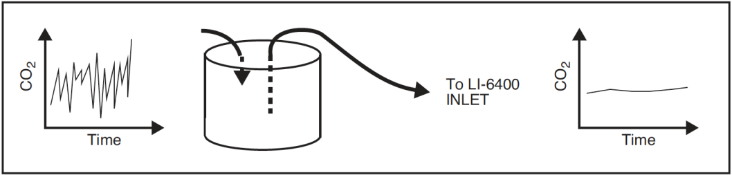
- Use a buffer volume
- When air is moved through a large, mixed volume, fluctuations in incoming CO2 are greatly dampened, and can be stable enough to use for gas exchange purposes (Figure 4‑14).
- Acceptable volumes depend on the magnitude of the fluctuations that need to be dampened, but several liters is a good starting volume. A plastic five gallon enclosed bucket is a good buffer volume, or - if nothing else - use the LI-6400 carrying case as a buffer volume.
- Use tank air, or some other source
- An advantage of an open system is that you can condition the incoming air stream, using CO2 tanks, humidifiers, oxygen generators, etc., prior to introducing that air to the leaf chamber.
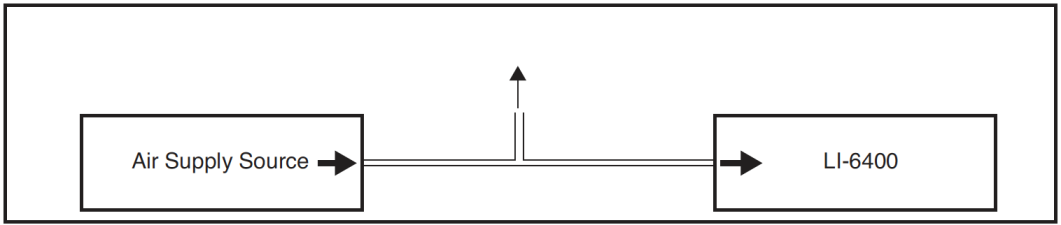
- You should plumb the system so that the LI-6400’s pump is used, even if the air supply has its own flow control (e.g. compressed gas). Figure 4‑15 illustrates how to do this using a T arrangement.
What’s the Light Source?
Make sure the <open> <light> <source> configuration node matches as closely as possible the actual light source you are using (Specifying the Light Source on page 8-4 in the instruction manual).
There are a couple of reasons for doing this. If you are using the 6400-02 or -02B Light Source, the function key for controlling this optional device depends on this configuration item. But even if you aren’t, the calibration of the in-chamber light sensor is adjusted to account for the light source, to minimize spectral errors in its calibration. See Light Sources and Sensors on page 8-1 in the instruction manual.
Also, don’t mix the 6400-02 (or -02B) and the LCF. That is, don’t configure the software for one, and use the other. The parIn readings won’t work.
Dealing With Low Rates
Measuring very low rates of photosynthesis or transpiration becomes problematic in an open system. Eventually, the CO2 or H2O differential becomes so small that it is in the noise level of the analyzers. Some things to try:
- Use as much leaf area as possible
- The more leaf area you can get in the chamber, the larger the differential that you can measure.
- Use as low a flow rate as possible
- Consider about 100 μmol s-1 an effective lower limit. If you have a CO2 mixer, then 50 is the low value. Leaks may be a problem, however. See Bulk Flow Leaks.
- Match the IRGAs
- As the differentials become small, the effect of any offset error is magnified.
Using Closed Mode
We have experimented with using a closed system technique in the LI-6400 to handle low rates. This is accomplished by turning off the pump for 10 or 15 seconds, and measuring the rate of change of CO2 with time, and H2O with time. The LI-6400 can be programmed to accommodate closed measurements interspersed at will among normal, open measurements. However, our tests indicate that the repeatability and accuracy of the closed technique is no better (and sometimes worse) than using the open method with a low (100 μmol s-1) flow rate. Contact LI-COR for further information.
Humidifying Incoming Air
The LI-6400’s humidity control balances the leaf’s transpiration with drier incoming air to maintain a desired humidity (see Humidity Control on page 7-7 in the instruction manual). How dry the incoming air is depends on the manual adjustment knob of the desiccant tube. The limitations of this approach become apparent when measuring a small leaf area and/or low transpiration rate when it is desired to have high humidity in the chamber. Another source of water besides the leaf is needed.
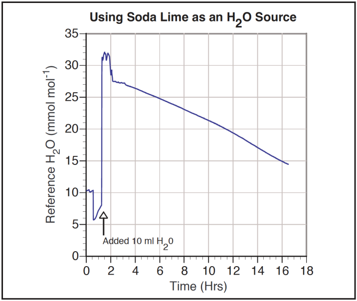
One solution to this problem if you are using the 6400-01 CO2 Mixer is to add a small amount of water (10 ml) to the soda lime tube (Figure 4‑16). After about an hour of subsequent use, the water output becomes quite stable, and remains so for many hours thereafter.
Note: The soda lime used for the experiment in Figure 4‑16 was a dry variety, which is no longer available. Most soda lime available now (for example, LI-COR part number 9964-090) is quite moist, so this procedure may not be necessary.
Caution: When adding water to soda lime, do it slowly, letting the chemical absorb the liquid. Then, hold the tube horizontally and shake it, to distribute the moistened (and clumpy) pellets. Avoid adding too much water; if liquid gets out of the tube during operation, downstream metal parts could become oxidized.
Another solution is to use a brand of soda lime that has a higher water output. In situations where you need fairly dry input air to the chamber, however, this material should be avoided, as it can saturate the desiccant tube in an hour or two, making frequent changes necessary.
Adding water to soda lime has an added benefit of helping to prolong or rejuvenate the CO2 scrubbing capacity of the soda lime. When it is used in dry environments (such as in a closed loop with a desiccant - not a normal configuration for the LI-6400), the scrubbing capacity of soda lime can be greatly diminished.
In dry environments when the 6400-01 CO2 Mixer is not in use (and little or no air is being routed through the soda lime tube), you can humidify the incoming air stream either by adding a tube with moistened filter paper or sponge to the system air inlet, or by replacing the desiccant in the desiccant tube with this humidifying material. The former method adds a tube to the system, but maintains a wide humidity control, while the latter method adds no hardware but sacrifices the ability to dry incoming air.
Controlling Low Flow Rates
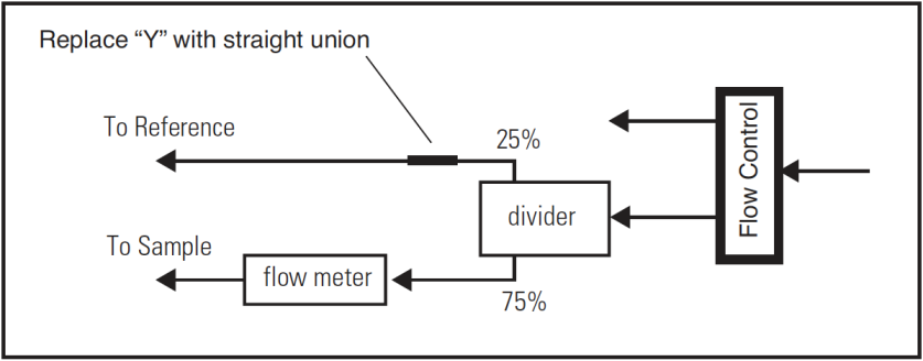
When the 6400-01 CO2 Mixer is installed, flow control is done with a flow diverter (Figure 4‑17). The excess flow from this device is dumped into the reference leg, providing faster response times in the reference IRGA.

(The complete schematic is in Figure 20‑19). However, when the flow control unit is routing most of the flow to the reference cell, there comes a point when some of that flow comes back through the flow divider and in fact goes to the sample cell. Typically with the 6400-01 CO2 Mixer, the lowest attainable flow is about 20 or 30 μmol s-1.
If low flows are needed for some special experiment, this behavior can be prevented quite simply by replacing the “Y” connector with a straight union (Figure 4‑18), and letting the flow from the flow controller vent to the atmosphere. This will allow precise flow control down to 0, but at the expense of horrendously slow response times in the reference IRGA at these low rates.