
Maintenance
Spare Parts Kit
This kit contains some common replacement parts for the 6400-09. If you need to re-order any individual parts, please refer to the part numbers shown in Table 28‑3. More part numbers are shown in Figure 28‑2.
| Part # | Description |
|---|---|
| 6000-09TC | Soil temperature probe |
| 6400-13 | Thermocouple adapter assembly |
| 9964-054 | Replacement parts kit |
| 6560-228 | Soil collars1 |
| 9960-112 | Gasket kit (foam gaskets and O-rings) |
| 620-04126 | Large plastic cap for soil chamber |
Soil Temperature Probe
The soil temperature probe cable insulation may have a tendency to work loose from the thermocouple connector shell. If this happens, open the connector (remove two screws) and stretch the cable insulation back into the shell, and reassemble.
The soil temperature probe can be ordered from LI-COR under part #6000-09TC, or directly from Omega Engineering Inc. (Stamford, CT) under part #MHP-CXSS-316U-6-SMP-M-NP.
Making Soil Collars
Soil collars can be easily constructed from thin-walled polyvinyl chloride (PVC) pipe (i.e., sewer and drain pipe). The tubing must have an inside diameter of 3.930” (10 cm) or larger [maximum 4.65” (11.8 cm) O.D.]. Cut a section approximately 1.75” (4.4 cm) long or longer, depending on your soil type and experiment, and bevel one edge with a grinding wheel so that it can be pressed into the soil. Soil collars are also available from LI-COR at a nominal cost under part #6560-228 (1 each).

IRGA Calibration
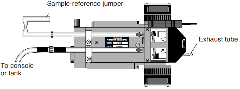
The normal calibration procedure is described on CO2 and H2O Analyzers. With the soil chamber in place, however, it introduces some issues. In order to zero or span, it is necessary to re-plumb the system. That is, the air supply, whether scrubbed air from the console for zeroing, or a span tank for spanning, must go directly to the sample IRGA (Figure 28‑38).
The second thing to do is prevent air from mixing between the soil chamber and the sample cell itself. One approach is to cover the end of the soil chamber with the plastic cap, and have the fan turned off to prevent exchange between the two volumes. This works pretty well as long as there is not high CO2 trapped in or floating around the chamber (i.e. work alone, and don’t breathe too much). Alternatively, you can loosen the four cap screws and place a piece of cellophane tape over the three holes that go to the IRGA sample cell volume.
To Zero the IRGA
- Connect the source
- If the console will be the source of the scrubbed air, then connect the “to chamber” air line (has black heat shrink on it) to the sensor head. Turn the soda lime tube on full scrub when zeroing for CO2, and the desiccant tube on full scrub when zeroing for H2O.
- Run the Zero Program
- The Calib Menu is slightly modified when configured for the soil chamber (Figure 28‑39). Pick the IRGA zero program.
-
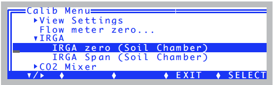
Figure 28‑39. The Calib Menu configured for soil.
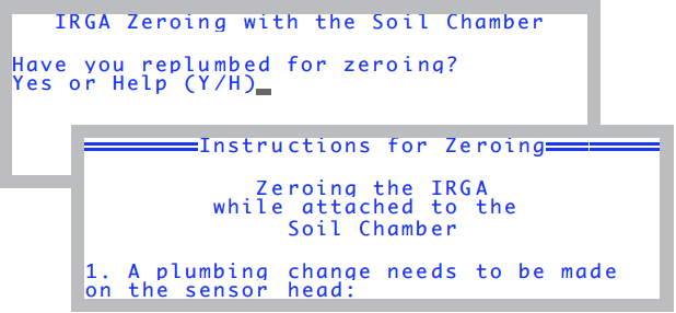
You’ll be asked if the plumbing is ready (Figure 28‑40).
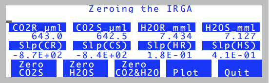
The soil zeroing program is much like the normal one (Setting the CO2 and H2O Zero), only this one is limited to the sample cell, and it has the chamber fan turned off.
To Set the IRGA Span
- Connect the span gas directly to the sample analyzer inlet
- Do not connect to the console. NOTE: If you also want to check the span of the reference analyzer, connect the gas directly to it when you are ready. Do NOT connect via the sample cell with the match valve on.
- Run the Span program in the Calib Menu
- You’ll get the same opening screen as the zeroing program (Figure 18‑8). After that, it runs the normal spanning program (Setting the CO2 Span on page 18-17, and Setting the H2O Span on page 18-20 in the instruction manual).