
CO2 and H2O Analyzers
Factory Calibration
The factory calibration of the infrared gas analyzers (IRGAs) consists of determining the coefficients of the polynomial f(x) for water (Equations (14-5) and (14-6) on page 14-6), and g(x) for CO2 (Equations (14-10) and (14-11) on page 14-8 in the instruction manual). The source for CO2 concentrations is a series (usually 13) of standard tanks, ranging in concentration from 0 to about 3000 μmol mol-1. Water concentrations are generated using a LI-COR LI-610 Dew Point Generator. IRGA calibration data is collected at a series of temperatures (typically 15, 30, and 45 °C), with the entire instrument in a temperature controlled chamber. The data are then standardized (concentrations are scaled by temperature, voltages are scaled by pressure), and the calibration curves generated: a 5th order polynomial for CO2, and a 3rd order polynomial for H2O. The coefficients for these curves are provided on the calibration sheet, and are retained in file system (/dev/.factory).
User Calibration (Zero and Span)
User calibration actions consist of checking and/or adjusting the zero and span. A zero is done with dry, CO2-free air in the IRGA cell, and the span is done with a known non-zero concentration in the cell.
How Often?
When OPEN first runs, it reads the most recent zero and span information from a file (/dev/.user), and applies it. Thus, user calibrations should carry over from one day to the next, once the instrument is warmed up. As for how often you should re-check them, your own experience should be your guide, but our experience is this:
For zeroing, If conditions (temperature, mostly) haven’t changed a great deal since the last time you zeroed the IRGAs, it won’t need adjusting. But, it doesn’t hurt to check it, as long as you know your chemicals are good, or have a tank that you know is CO2-free. You will do more harm than good, however, if you dutifully re-zero every day using chemicals, but ignore the condition of those chemicals.
For spanning, if you’ve got a standard you trust, then you can adjust the IRGA to match that standard. It shouldn’t need subsequent adjusting for months and months, however. If you don’t have a good standard, then don’t bother with the span. Just leave it alone.
Setting the CO2 and H2O Zero
The procedure for checking the IRGAs’ zero is part of the daily warm-up tasks, described in After Warm Up on page 4-4. If you find that an adjustment is necessary, then do one of the following procedures: use the chemical tubes to obtain dry, CO2 free air (described below), or use CO2-free air from a tank.
Zeroing With Chemicals
While it is probably best to use tank air for zeroing, it can be done with chemicals. Being able to trust the chemicals to thoroughly scrub the air involves a certain amount of “procedures and practice”, including knowing when and from where the chemicals were purchased, how and where they were stored, etc. Just because you changed the chemicals in the tubes recently does not necessarily mean that they are good.
- Select "IRGA Zero" in the calibration menu
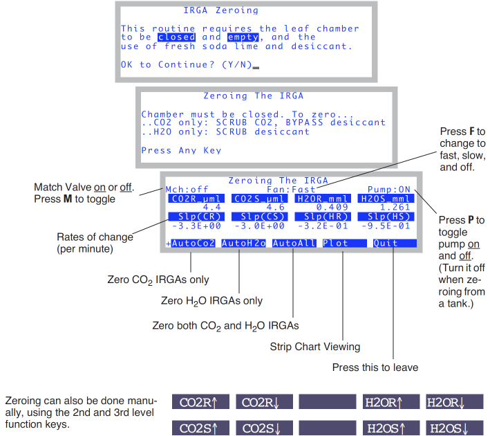
- You'll be greeted with a couple of prompt screens, followed by the main screen (Figure 18‑8):
- Soda Lime: full scrub and Desiccant: full bypass
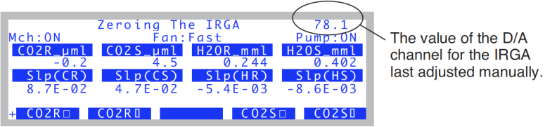
- Figure 18‑8 illustrates the IRGA zero screen. We’ll do CO2 first, because it’s quickest. Put the desiccant on full bypass, because (if it’s Drierite) it will buffer CO2, resulting in a longer time to reach zero as it flushes out.
- Wait for stability
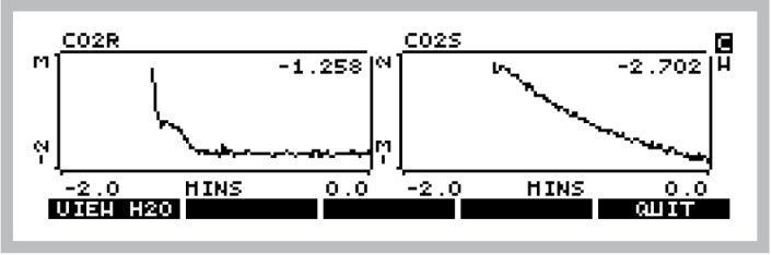
- Watch CO2R_μml and CO2S_μml (reference and sample cell CO2 concentrations), and also their rates of change (Slp(CR) and Slp(CS)). and when they get as low as they will go, you are ready. (If you wish to see this graphically, press Plot(f4). A typical plot is shown in Figure 18‑9). To return to the normal text display, press escape or QUIT). It should take less than 2 minutes to get reasonably stable readings.
- If re-zeroing is necessary, press CO2RS→ 0 (f1).
- If both CO2 values are within 5 μmol mol-1 of 0, you can skip this if you wish1. If you do the press CO2RS->O, it will take about 30 seconds to do its measurements and calculations, and establish new zeros.
- When it’s done, both the CO2R_μml and CO2S_μml values should be within 1 μmol mol-1 of 0.
- Soda Lime: full scrub Desiccant: full scrub
- Now we do the water zero. Since water sticks to everything, it can take many minutes to come to a reasonably stable “dry” reading, since the chamber and IRGA surfaces are continually giving up water vapor to the suddenly drier air within the system.
- Monitor H2OR_mml and H2OS_mml, and their rates of change Slp(HR) and Slp(HS). (If you want to do this graphically, press plot (f4) then H).
- This process can be speeded a bit by removing the upper half of the chamber from the system. This is done by clamping onto a sheet of something gas impermeable (like Propafilm or Saran) that covers the entire chamber AND the three rear holes over the IRGA.
- After a couple of minutes, if it’s clear that both IRGAs are heading for something close to zero, then call it good (the same rationale as in the footnote to step 4 applies here as well) and jump ahead to step 7. Otherwise, wait it out for 15 minutes2 or so, and…
- Press H2ORS→0 (f2) when it’s stable
- It takes about 30 seconds to accomplish the zero, after which you are done.
- Press Quit (f5) to exit
Zeroing With Compressed Gas
Instead of using the chemicals to zero, you can use air from a tank, such as compressed CO2 free air, or dry nitrogen. Be careful with the latter - these tanks may have 10 or 20 μmol mol-1 of CO2 in them, and would thus require a tube of soda lime in-line to remove it. If you have doubts, use a tube of soda lime to test it. The compressed air should be suitably dry, however.
- Use a modest flow rate
- If you have a way to measure flow from your tank, use about 0.5 l min-1. If you don’t, then simply adjust the flow so that you can just feel it if you hold the tube next to your moistened lower lip. Flow rate is not very important for zeroing, as long as it’s adequate to get the cells flushed out in a timely manner. (Safety tip: establish the flow rate before connecting to the sensor head.)
- Connect directly to the sensor head
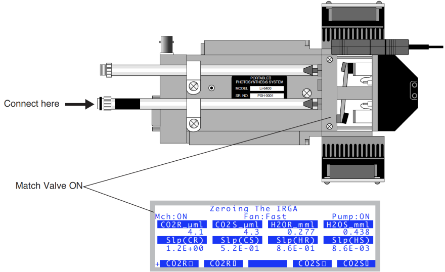
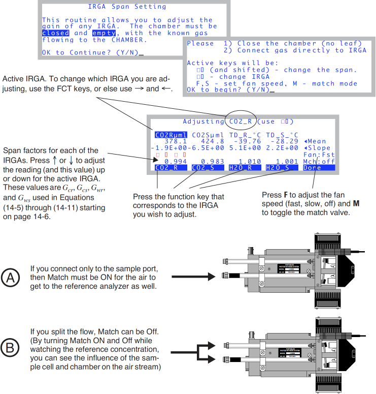
- It is simplest to connect the output of the tank’s regulator directly to the sensor head, and bypass the console. There are two ways to do this: either connect to the sample inlet, and use the match valve to get that air into the reference afterwards, or use a “Y” connection and flow air to both sample and reference IRGAs simultaneously. Both methods are illustrated in Figure 18‑13. The preferred method is to use a “Y” connector.
- Use the IRGA zero program
- It’s the entry "
IRGA Zero" in the Calib Menu. - Turn off the Pump
- Since you don’t need the pump, you can turn it off by pressing P.
- Match ON (if necessary)
- If you are using a single line connected to the sample inlet, put the match valve in the proper position by pressing M, once the IRGA zero program is running. Note that now the reference IRGA will be seeing any leaks that occur in the sample cell, so make sure there are none (chamber closed).
- To shorten the dry down time, block the upper half of the chamber, as explained in step 5 under Zeroing With Chemicals.
- When stable, press All→0
- Since the air source is dry and CO2 free, you can zero both IRGAs simultaneously.
What Can Go Wrong When Setting The Zero
When automatically zeroing the IRGAs, two things are done for each IRGA:
1) a D/A (digital to analog output) channel is set. The resolution of these channels is fairly coarse (19mV), so to make the zero really zero, 2) an adjustment term is computed. This second step ensures that the IRGAs will always zero - even if you zero the IRGA without having dry or CO2 free air in them, and are outside the range that the D/A portion can handle. It is therefore a good idea to check the values of these two components to make sure they are both reasonable (see View Current).
- Not Zero Air
- The most common problem results from zeroing the IRGAs with air that’s not really CO2-free, or not really dry.
- Post-Zero Drift
- After zeroing the CO2 and/or H2O IRGAs, if you see continued drift before exiting the zeroing routine, it likely means that you zeroed them too soon, be- fore they had equilibrated. This is especially true of water vapor.
- Didn’t zero very well
- CO2 should be within 1 μmol mol-1 of zero after zeroing, and H2O should be within 0.1 mmol mol-1 of zero. If things are off more than that, go check the values (View Current). It may be that you had very non-zero air when you zeroed, or else the IRGA has a problem.
Individually Zeroing the IRGAs
The big advantage of zeroing the reference and sample cell individually is that it is much faster. Here's why: first you zero just the reference cell, which always stabilizes much sooner than the sample cell. Then, you turn on the match valve so the reference cell sees the sample air, and you adjust the scmple cell to match the reference cell reading. Here's the step-by-step:
- Connect with a “Y” if you are using tank air.
- See part B of Figure 18-12 on page 18-19 in the instruction manual.
- Match valve OFF.
- Flow the zero air, wait for reference cell stability.
- Zero the reference cell
- Press 2 to get the level 2 fct key labels, which should look like this with the match valve off:

- Press f1 to zero CO2, and/or f3 to zero H2O.
- Match Valve On
- Press m to turn on the match value, and the fct key label should change to

- Match Sample to Ref
- Wait 10 or 15 seconds for the reference cell to get flushed out, and replaced with sample cell air. Then press f2 (and/or f4) to “zero” the sample cell. (It is a zero adjustment, but the target is no longer 0. Instead, the target is whatever the reference cell is reading.)
Manual Adjustment Keys
The manual zero adjustment keys are on levels 3 and 4. You can probably
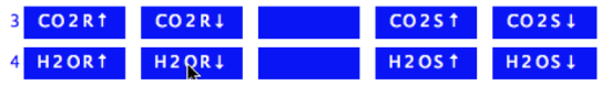
safely ignore them, since their historical use was automated in the level 2 fct keys in version 6.2. They allow direct control of the 4 D/A channels that do the coarse adjustment of zeroing. When one of the manual zeroing function keys is pressed, the value of the D/A channel that controls that IRGA’s zero is displayed in the upper right (Figure 18‑11).
Setting the CO2 Span
To check the span of the CO2 analyzer, you’ll need a known concentration of CO2. Generally, this is provided by a tank of compressed gas (CO2 in air, not nitrogen) that has been certified, or (even better) that has been measured using a correctly calibrated gas analyzer. The concentration should be at or above where you work most of the time, so 400 or 500 μmol mol-1 is fine3.
Setting the CO2 IRGA gain is a process by which the user can manually (using the arrow keys ▼▲) adjust the values of Gcr and Gcs (these items are defined in Equations (14-10) and (14-11) on page 14-8 in the instruction manual).
Checking/Setting the CO2 Span
Look at Figure 18‑13.
- Select "IRGA span" from the Calib Menu
- Set the flow from the tank.
- See the comments under step 1 on page 18-14 in the instruction manual.
- Attach to the IRGA.
- You have a choice here, as shown by Figure 18‑11: Attach to the sample inlet on the sensor head, and have Match ON,
- -or-
- Use a Y connector to split the flow, and attach to both sample and reference ports simultaneously, and have Match Off.
- Adjust the span settings as needed
- When CO2Rμml is highlighted, you are adjusting the CO2 reference IRGA’s span factor. The sample IRGA is CO2Sμml.
-
The span values should be close to 1.0, as described in What Can Go Wrong Setting the Span).
Setting the H2O Span
To check the span of the H2O analyzer, you’ll need a known concentration of H2O. The best choice for this is the LI-COR Dew Point Generator (LI-610).
If you do not have an LI-610, or some device of similar accuracy, do not adjust the IRGA span values for water.
The H2O IRGA gain adjustment is a process by which the user can manually (using the arrow keys ▼▲) adjust the values of Gwr and Gws (see Equations (14-5) and (14-6) on page 14-6).
To set the H2O Span
- Setup the LI-610 for an appropriate dew point
- Subtract about 5 °C from room temperature, and use that for the target dew point temperature. Wait until the condensor’s temperature (as monitored on the LI-610) reaches this target.
- The reason for this 5 °C “buffer” is to avoid condensation in the line between the LI-610’s condensor and the IRGA. If condensation happens, you will have large errors.
- Set the flow rate.
- Use about a 500 ml min-1 flow from the LI-610.
- Attach to the IRGA
- You have the same choice, as shown in Figure 18-12 on page 18-19 in the instruction manual. Here, however, we would recommend option B: splitting the flow and connecting both the reference and sample, with Match Off. The reason for this is that you will be able to drastically reduce the equilibrium time, waiting for the sample cell, as you will see.
- View water channels
- Press F3 or F4 to make the water IRGAs the active ones.
- Wait for equilibrium
- Watch the rates of change (slopes). If you are using Option A (connected to sample, Match On), then be prepared to wait about 20 minutes, until the rise in sample and reference concentration is negligible.
- If you are plumbed for Option B (sample and reference connected), ignore the sample, and only wait for the reference to equilibrate. 3 to 5 minutes should be adequate.
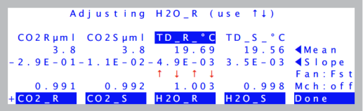
- Adjust the reference gain as needed
- When Td_R_°C is highlighted, press ▲ and ▼ to adjusting the H2O reference IRGA’s span factor until Td_R_°C reads correctly (Figure 18‑13).
- Select the sample IRGA
- Press ► (or f4) to highlight Td_S_°C.
- If you are plumbed for Option B, continue with Step 8.
- If you’re plumbed for Option A, press ▲ and ▼ to adjust Td_S_°C until it reads correctly. You are done.
- Match mode ON
- Press M to make the Mch: indicator read ON.
- Note the reference dew point value
- Watch the Td_R_C value. It will likely drop a bit, as the still unequilibrated air from the sample cell enters the reference cell. When it stabilizes (30 seconds), set the sample IRGA (Td_S_C) to read the Td_R_C value.
Do you see the trick here? We’ve just spanned the reference IRGA so it’s reading correctly. The sample IRGA is seeing slightly drier air because water sorption is still going on, and we’re losing water to the walls of the sample cell. When we put match mode on, the reference cell changes from seeing air directly from the dew point generator, to air that has been modified by the sample cell. This allows us to measure the sample cell dewpoint. We then use this value as a momentary target for setting the sample IRGA.
What Can Go Wrong Setting the Span
The span factors should be within 0.05 of 1.0 (that is, 0.95 to 1.05)4. The farther out of this range you go in attempting to make the analyzer read the correct concentration, the more likely it is that something is wrong:
- Badly zeroed analyzer
- Make sure you have a good zero before setting the span.
- Concentration not what you think it is
- (CO2) Has the span gas ever been independently checked? Don’t believe even the most reputable vendor of calibration gasses; after all, someone could have accidentally put the wrong label on the tank or its paperwork. It happens.
(H2O) Is there water in the condenser? Are you asking for a target that is at or above the room temperature? (If so, you won’t get that dew point, but you will get trouble in the form of condensation somewhere in the line.) - Leak in the chamber
- The chamber has to be well sealed for this to work.
- Match valve set correctly?
- If the match valve isn’t in the right position, the sample cell will be seeing the tank air, but not the reference cell. Also, is the match valve in fact working? Don’t trust the display - look at the underside of the IRGA to see its position.
- Plumbing mistake
- (CO2) Is the tank air really getting to the sensor head?
(H2O) Is the LI-610 pump on? Is there flow going to the sensor head?
(Both) Is the tube connected directly to the sensor head Do NOT connect the tank or LI-610 to the console Input air connector when setting spans. Space does not permit listing all the reasons why that is a bad idea. - “IRGAs Not Ready”?
- If this message is flashing on your display, then there are more pressing problems to be addressed (see “IRGAs Not Ready” Message), and you certainly shouldn’t be setting the span.
- IRGAs not responding
- See IRGA(s) Unresponsive.