
IRGA Problems
The IRGA Diagnostic Screen
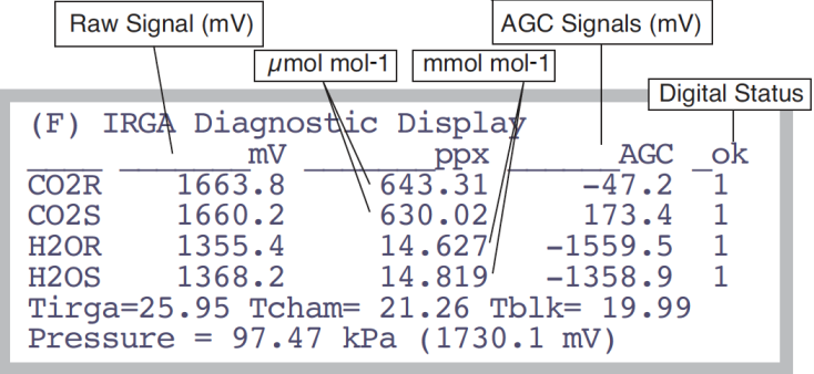
A very useful display when troubleshooting the gas analyzers is the IRGA Diagnostic Screen (Figure 20‑4). In New Measurements mode, press [, followed by F to see it.
Raw Signals
This values represent the IRGA’s raw output. They are useful in deducing of a problem is hardware or software related. The final concentrations, which you normally see while operating, are computed from the raw numbers, plus a lot of other things: calibration coefficients, zero and span corrections, temperatures, pressure, etc. If the final values don’t make sense, but the raw numbers do, then the problem is likely software (that is, bad calibration, etc.). A typical relationship between raw and final values is shown in Table 20‑1.
| raw signal mV | CO2 μmol m-2 s-1 | H2O mmol m-2 s-1 |
|---|---|---|
| 0 | 0 | 0 |
| 500 | 130 | 4 |
| 1000 | 300 | 9 |
| 2000 | 750 | 24 |
| 4000 | 2300 | 70 |
AGC voltages
The AGC signals are shown the IRGA Diagnostic Screen (Figure 20‑4). These signals indicate how much radiation is attenuated in the reference wave band (nonabsorbing for both CO2 and H2O). With a good IR source and clean optics, these values are typically 0 or less. As the optics be- come dirty, these values will increase. Eventually (near 5000mV), the mes- sage “IRGAs Not Ready” will appear (and the CO2 and/or H2O status indicators (level c in the diagnostics display, j in the standard display) will stop showing OK).
Digital Status
1 is OK, 0 is not ok. If any of these are not OK, then this is the condition for the “IRGAS Not Ready” message, discussed next.
“IRGAs Not Ready” Message
The “IRGAs Not Ready” message will show up in New Measurements mode, and also during the IRGA zeroing and span setting routines, whenever one or more of the gas analyzers is indicating a problem (see discussion under “CO2” and “H2O” on page 14-15 in the instruction manual). What triggers this message is “too much” light attenuation in the non-absorbing reference wave bands for CO2 and H2O. Causes:
- Power
- IRGA connector not seated, bad cable, blown analyzer board fuse.
- IRGA not functioning
- If power is getting to the IRGA, but it is still not functioning, the chopper motor may be stalled.
- Low Light
- Too much debris in the sample cell, dirty optics, or a failing source or detector.
Solving “IRGAs Not Ready”
Here is a logical step-by-step to resolve the problem.
- Are the IRGAs warmed up?
- The message should go away within 2 or 3 minutes of when the IRGAs are powered on.
- Round connector fully seated?
- One cause of “IRGAs Not Ready” is the IRGA connector not being fully plugged in. The connector in question is the round one that attaches to the sensor head. There are two red dots on the mating halves of the connector, and they will be nearly touching when the connector is fully seated. When making the connection, push the connector in until you hear a snap (which we trust wasn’t a weak bone in your wrist giving out).
- Is the chopper motor running?
- Determine if the chopper motor is stalled (see Stalled Chopper Motor on page 20-20). If the chopper motor is running, continue with Step 4. Otherwise, we are down to three possibilities: 1) a blown analyzer board fuse, 2) a bad cable (between the console and the sensor head), 3) bad chopper motor. If it is one of the latter two things, then contact LI-COR.
- Check the AGC voltages
- These values are described in Table 20‑1. If the reference cell AGC values are well below 5000, but the sample ones are >5000, then clean out the sample cell.
- Contact LI-COR
- If you’ve gotten to this point (the chopper motor is running, and the chamber and optics are clean, but “IRGAs Not Ready” persists), then contact LI-COR.
IRGA(s) Unresponsive
Unresponsiveness is when CO2 and/or H2O doesn’t seem to respond to what should be large changes, such as blowing into the chamber, or changing the chemical tubes from full scrub to full bypass.
- Power? (Fuses, Cable, Connector)?
- Lack of power to the IRGA usually would trigger the “IRGAs Not Ready” message, but not always. The unpowered, digital status lines from the IRGA could just happen to be in their “ready” states, so perhaps the IRGA is not powered. Check the connector and the fuse.
- Bad calibration?
- Check the zero and span values in the <user> node in “View Current...” under “View Settings” in the Calib Menu. The span values should be close to 1.0, and the zeros will be between +/- 5000, but the closer they are to either limit, the more suspect they are. Typically, they are numbers in the hundreds. Try resetting the zero and span values to factory settings to see if that makes a difference.
Unstable CO2 and/or H2O
The noise of the LI-6400 analyzers is typically 0.2 μmol mol-1 for CO2, and 0.04 mmol mol-1 for H2O. Leaks, diffusion, inadequate chemicals, and fluctuating inputs are some of the things that can increase apparent signal noise.
Tracking down a noisy signal
This discussion assumes CO2 is the noisy quantity, but similar logic applies to H2O (except for Step 2).
- Is it really noisy?
- Remember that 0.2 μmol mol-1 is typical noise for CO2, and 0.04 mmol mol-1 is typical for H2O. These values will be larger at higher concentrations. A good method for quantifying these values is to add CO2R, CO2S, H2OR, and H2OS to the stability list. Then you can monitor the running standard deviations of those signals.
- Are you using the CO2 Mixer?
- Shut it off, and continue with these steps. If you don’t locate the problem, try 6400-01 CO2 Mixer Problems.
- Is the instability flow dependent?
- Close the chamber, and stop the flow (2 f2 N). If the instability seems to go away, then a leak or fluctuating input is suggested. See Finding Leaks. If the test was inconclusive, keep reading.
- Is the instability fan dependent?
- If the instability is only in the sample cell, and if it goes away or is much reduced when the chamber fan is turned off, then the problem is likely some fuzz or hair or small particles that are moving around in the sample cell while the fan is on. Clean the cell (see Cleaning the Optical Bench).
- Another possibility is that the fan itself is causing the instability. See Noise caused by the Fan Motor.
- Feed stable air directly to the sensor head
- A more definitive test is to feed a constant concentration (e.g. air from a tank) directly to the sensor head, much like the configuration when setting the span. In fact, you can use the span setting routine in the Config Menu to gain control over the match valve (but don’t actually change the span). With a flow of stable air going through both IRGAs, is the signal now much more stable? If yes, consult Finding Leaks.
- View the AGC voltages
- If the IRGA sample signal is noisy, but an unstable input or leaks don’t seem to be the problem, the next thing to check is for foreign objects in the sample IRGA. There is a way to check for this without disassembling the IRGA, however; look at the AGC voltages (discussed in AGC voltages).
- Observe the sample cell AGC signals. They should not be varying by more than a mV or so. If they are fluctuating more than that, and if the reference ones are stable, that could indicate that there is debris being blown about in the sample cell. If the reference values are jumpy, it could be electronics or a chopper motor problem. Instability in just one of the four channels could indicate a demodulator board problem: go to Step 9.
- Check the raw voltages
- If the problem isn’t debris in the sample cell, and isn’t leaks or fluctuating input concentrations, then it suggests an IRGA hardware problem, or some other variable (temperature or pressure) is fluctuating, causing the instability. One way to eliminate the latter possibility is to monitor raw IRGA signals. Use the Diagnostics display (The Diagnostic Text Display), and view display line b. If the raw IRGA signals are not stable (fluctuations > 2 mV), go to Step 9.
- Check pressure and temperatures
- If the IRGA mV values are stable, but the molar concentrations aren’t, then look for instability in pressure, IRGA temperature, chamber temperature, and block temperature. (All of these are on the The IRGA Diagnostic Screen.) Pressure is used for both sample and reference concentration computations. Block temperature is used for reference concentrations, while the average of block and air temperatures are used for the sample cell. (The equations are on pages 14-6 and 14-8 in the instruction manual.)
- If the culprit is pressure or temperature fluctuations due to sensor or circuitry problems, there’s not much to do except the final step in this sequence, which is to contact LI-COR. There is a stop-gap work-around, however, that could keep you going, and that’s to use a constant value instead of a measured one for the offending sensor. You could, for example, change the pressure sensor’s calibration coefficients to 98 and 0 (offset and slope), which would cause pressure to remain fixed at 98 kPa.
- Contact LI-COR
- If you have gotten to this point by carefully following the logic, you have determined that the instability is not due to fluctuations of concentration in the incoming air, leaks, debris in the cell, or unstable temperature or pressure signals. An IRGA hardware problem is suggested, so contact LI-COR.
Readings Obviously Wrong
If you just don’t believe the IRGA readings, then try these steps:
- Is it responsive?
- Watch reference readings, and go from full bypass on both soda lime and desiccant, to full scrub. If the IRGAs don’t respond, turn to IRGA(s) Unresponsive.
- Zero and Span
- Check the present values found in “View, Store Zeros & Spans” in the Calib Menu. (For a discussion of these numbers, see Managing Calibration Data on page 18-2 in the instruction manual.) Try resetting them to the factory defaults, or follow the zero and span setting procedures starting on page 18-11 in the instruction manual. A common cause of problems here is zeroing the IRGAs without having a truly CO2-free or H2O-free air stream.
- Verify that the chamber fan is operating
- Without mixing the sample cell, a leaf will have little effect on the sample IRGA readings, which can make for strange behavior. The verify the fan’s operation, use your ears: turn the fan off (3 F3 O (that’s a letter, not a number)) and on again (F3 F), and listen for the sound changes, if any. (No sound change - no fan - no good.)
Occasional Instability
This problem is characterized by an occasional jump in the IRGA reading, for no apparent reason. Before deciding there is an electronic problem, eliminate a couple of other possibilities:
- Insects?
- Flying insects can fairly easily get into the sample cell when the chamber is open, or even into the match valve. Those that find the sample cell are destined to eventually encounter the mixing fan and become debris, but prior to that, you will be seeing the effects of insect respiration on your measurements. So, if you see periodic spikes in the sample CO2 (such as 5 or 10 μmol mol-1 every minute or so), you may have acquired a guest.
- Leaks?
- Check for leaks (Finding Leaks).
- Connections?
- See if there is any relationship between the jumps and movement of the cable. There could be a faulty connection at work. Monitor the CO2 sample and reference concentrations with a strip chart. That makes it easier to detect a jump.
Stalled Chopper Motor
The chopper motor is the motor that spins the filter wheel in the IRGA/sensor head. This motor should begin to run shortly after the IRGAs are powered on. If the chopper motor does not run, the “IRGAs Not Ready” message will be displayed in New Measurements mode. The typical chopper motor failure is due to the bearings. So, prior to its demise, there may be increased audible noise coming from the motor, and even subsequent electronic noise in the IRGA signals.
Determining if the Chopper Motor is Running
- Turn off the pump and chamber fan
- In New Measurements mode, turn off the pump (2 f2 N) and chamber fan (3 f3 O [the letter, not the number]), so you can hear the chopper motor.
- Put the LI-6400 to sleep
- Go to the Utility Menu, and select “Sleep Mode”. Listen for a motor in the sensor head (NOT the console) to wind down once you press Y indicating it is OK to sleep.
- Wake the LI-6400 up
- Exit the Utility Menu. The fan in the console will begin running immediately, but listen for the chopper motor to begin running after that (press your ear to the IRGA); it should start anywhere from 10 seconds to 1 minute later.
If you don’t hear the chopper motor, the problem could be a blown analyzer board fuse, a not-fully-seated IRGA connector, a bad cable, or a stalled chopper motor.
Restarting a Stalled Chopper Motor
If you didn’t hear any evidence of a running chopper motor in the above sequence, then you can try starting it.
- Make sure the IRGA is powered
- Being in OPEN’s Main Screen, or in New Measurements mode, is sufficient for this.
- Have the pump and fans off so you can hear
- Same as Step 1 under Determining if the Chopper Motor is Running above.
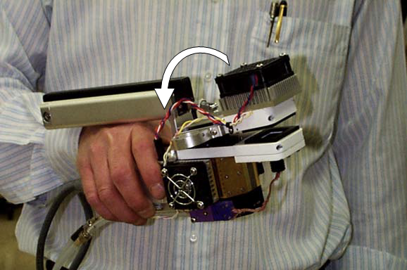
- Move the filter wheel by inertia
- Grasp the IRGA, and give it a quick roll (left or right) (Figure 20‑5). You may have to be aggressive; if the bearings are getting bad, it might not start easily.
- Temperature Control Problem?
- Another possibility is that the chopper has stopped due to lack of temperature control. If the IRGA has gotten above the specified operating temperature (50 °C), or if something has failed in the temperature control circuit, it can cause the chopper to quit. If the IRGA is hot, cool it down to about 30 °C and see if it starts working.