
IRGA Maintenance
Chemical Bottles
There are two small plastic bottles in the analyzer housing designed to keep the detectors free of CO2 and water vapor. They contain a mixture of anhydrous magnesium perchlorate and Ascarite II that should last for three or more years.
Note: Instruments built or serviced at LI-COR prior to about January 2003 will have soda lime instead of Ascarite for the CO2 scrubber. That combination needs to be changed annually, since the magnesium perchlorate desiccates the soda lime, rendering it ineffective, ultimately resulting in calibration drift and instability.
To change the sensor head soda lime/desiccant bottles:
- Open the covers, remove bottles
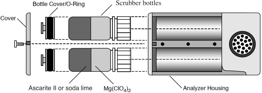
- The plastic bottles are located in the analyzer housing in the sensor head. They are accessed by removing the cover plate on the left side of the analyzer housing (Figure 19‑28). There are two bottle covers, each with an O-ring seal, beneath the housing cover (Figure 19‑30). Pull up on the bottle covers to expose the bottles; the O-rings can expand to form a very tight seal, so you may have to pull hard.
-
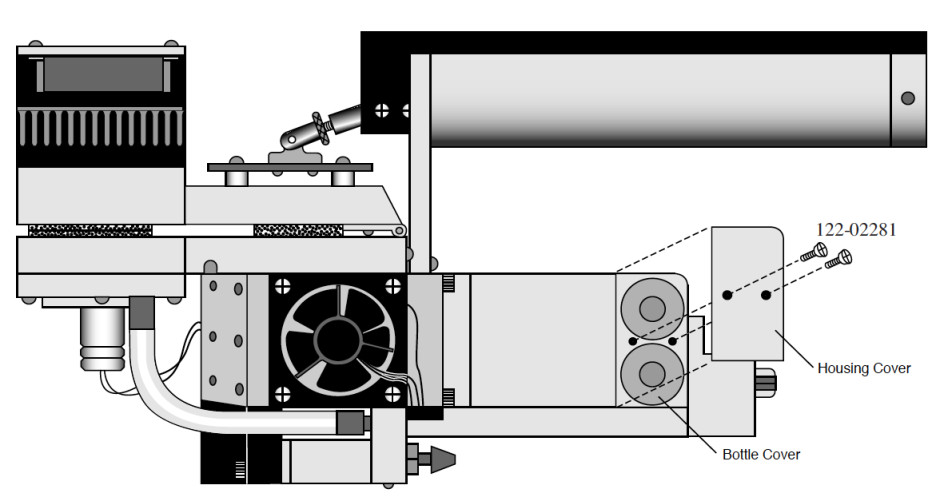
Figure 19‑28. Remove the two screws that secure the housing cover. - Prepare new bottles
- Part number 6400-950 consists of two internal scrub bottles already filled with magnesium perchlorate and Ascarite II.
- If you do not have a 6400-950, you will need to prepare the chemicals yourself. Fill the two bottles with equal parts Ascarite II (or dry soda lime - do not use the 9964-090 wet soda lime) and magnesium perchlorate. Fill the bottles half full with Ascarite, followed by the magnesium perchlorate. Place a filter paper disk in the lid to keep the chemicals from spilling into the detector housing.
-
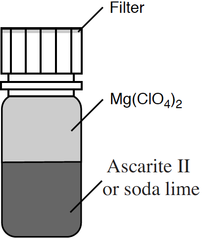
Figure 19‑29. Fill the bottles with the CO2 scrubber, followed by magnesium perchlorate. - Insert the new bottles
- Insert them lid first into the analyzer housing. Seat the bottle cover with the attached O-ring, and secure the housing cover with the two screws.
- Wait before use
- When the bottles are changed, allow one day for the detector to equilibrate again.
- Magnesium perchlorate is the recommended desiccant. Do not use any other desiccant. Several grades of magnesium perchlorate are available from commercial suppliers. One type that works well is marketed under the name Dehydrite, and is available (catalog number C260-M61) from Arthur Thomas Company, Vine St. & 3rd, Philadelphia, PA 19105. (215)574-4500.
Caution: Magnesium perchlorate is a strong oxidizing agent. Contact with skin or mucus membranes may cause irritation. Avoid bringing it into contact with acids and organic substances such as cotton, rubber, grain dust, etc. Consult the container label.
Cleaning the Optical Bench
Because the LI-6400 contains open path analyzers, it is possible for air-borne debris to enter the system and contaminate the sample optical path.
When the analyzers become too dirty, the “IRGA(s) not ready” message will be displayed in New Measurements mode. There are other causes of this message, however (see “IRGAs Not Ready” Message).
Cleaning the Mirrors
The easiest way to open up the optical path for partial cleaning is to remove the mirrors.
To remove and clean the mirrors
- Remove the bottom chamber
- Remove the chamber bottom by disconnecting the thermocouple, exhaust tubing, and removing the two screws that hold the chamber in place.
- Remove the six screws from each gold mirror
- Use a 5/64 hex key. Be careful. They are small screws.
- Clean the mirrors
- Wash with ethanol or water, and wipe dry. Use a cotton cloth (e.g. an old Tee shirt) on the mirror surface. Do not use a cotton swab, as they tend to scratch.
- Hint: A mirror that seems clean when you are looking straight at it may have residue that appears when viewed at an oblique angle. Look at the mirror from several angles before you deem it “clean”.
- Look inside
- Check for debris that may be inside the cell. You could blow out the cell with clean, pressurized air. If you are tempted to reach in with a Q-tip or cotton swab to clean the windows at the back of the optical bench, be careful not to snag the cotton on the sharp corners near the front. If you do get fuzz snagged there, it will blow in the wind when the chamber fan is running, and you’ll have increased signal noise from the IRGAs.
- Reassemble
- Be careful when re-installing the mirrors. The screws are small, and excess force will break them, creating a major problem.
Opening the Optical Bench
If access via the mirrors is inadequate, then open the whole thing up:
To disassemble the sensor head and clean the optical path:
- Remove the handle from the sensor head.
- Described in The Chamber Handle.
- Remove the upper half of the leaf chamber.
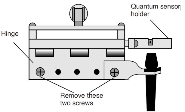
- Remove the two screws from the hinge on the rear of the upper half of the leaf chamber (Figure 19‑31). The upper portion of the leaf chamber can now be moved aside; unhook the connector from the PAR sensor or LED Light Source, if necessary.
- Remove the optical bench cover.
- Pull off the air hose from the underside of the leaf chamber.
- Remove the male end of the thermocouple connector by pulling straight out.
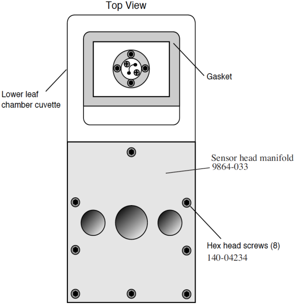
- There are eight hex head cap screws on the optical bench cover, as shown in Figure 19-32. Remove the cap screws with a 5/64” hex key (in the spares kit). The cover with attached lower half of the leaf chamber can now be removed.
- Clean the windows
- Moisten a cotton swab and swab the two optical windows for the sample cell (Figure 19‑33).
- If you haven’t done so already, you can also remove and clean the two gold plated optical mirrors by unscrewing the six cap screws on each mirror. See comments on Step 3 on Cleaning the Mirrors.
- Allow the mirrors to air dry before reassembling the sensor head.
- Reassemble the sensor head.
- Note that there is a thin vinyl gasket on the top surface of the optical bench (Figure 19-33). This gasket is reusable; it should adhere to the optical bench. If it becomes detached, be sure to reposition it before reassembly. Tighten (but not overly so - they’re small and can break) the eight screws evenly.
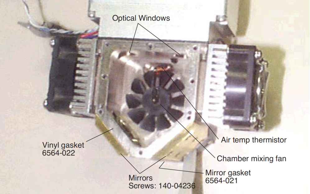
Note that one of those screws (nearest the label “Mirrors”) in Figure 19-33 goes through an air channel in the optical bench cover. If this screw is not snug, there will be an air leak.