
Creating custom interface dialogs
It can be very helpful to put a user interface on a BP to guide the user, especially when the user is not the program designer. Consider, for example, a simple BP for doing a light response curve (Figure 12‑17).
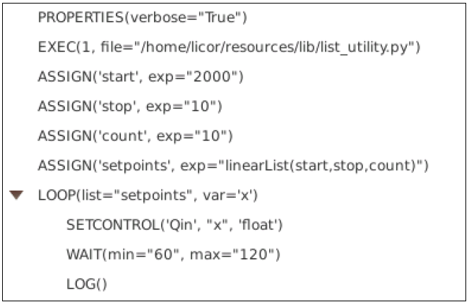
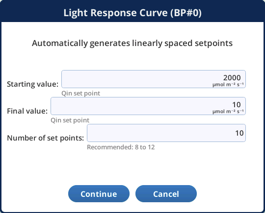
This program has three parameters (starting setpoint, ending setpoint, and increment). If someone (not the designer) wants to use this program but needs to modify the settings, they have to do so in the BP editing environment, where - if they aren't sure of what they are doing - they could inadvertently render the program unworkable. It would be better if the program simply presented the user with something like Figure 12‑18.
Happily, setting up such a dialog for a BP is fairly simple, since there is a DIALOG step that does most of the work for you. If there are variables in your BP you want to edit, or if you want to let the user control the program's actions via buttons or check boxes, there will be a few code additions needed to handle that. In general, however, there are three basic steps:
- Insert a DIALOG step in the BP at an appropriate place in the execution flow that you want the dialog to appear.
- If the dialog allows for editing program variables, revisit the ASSIGN steps for those variables and fill in the dialog-related information for whatever interface you choose.
- If your program flow is going to depend on what button was pressed, or the state of edited variables, add that code.
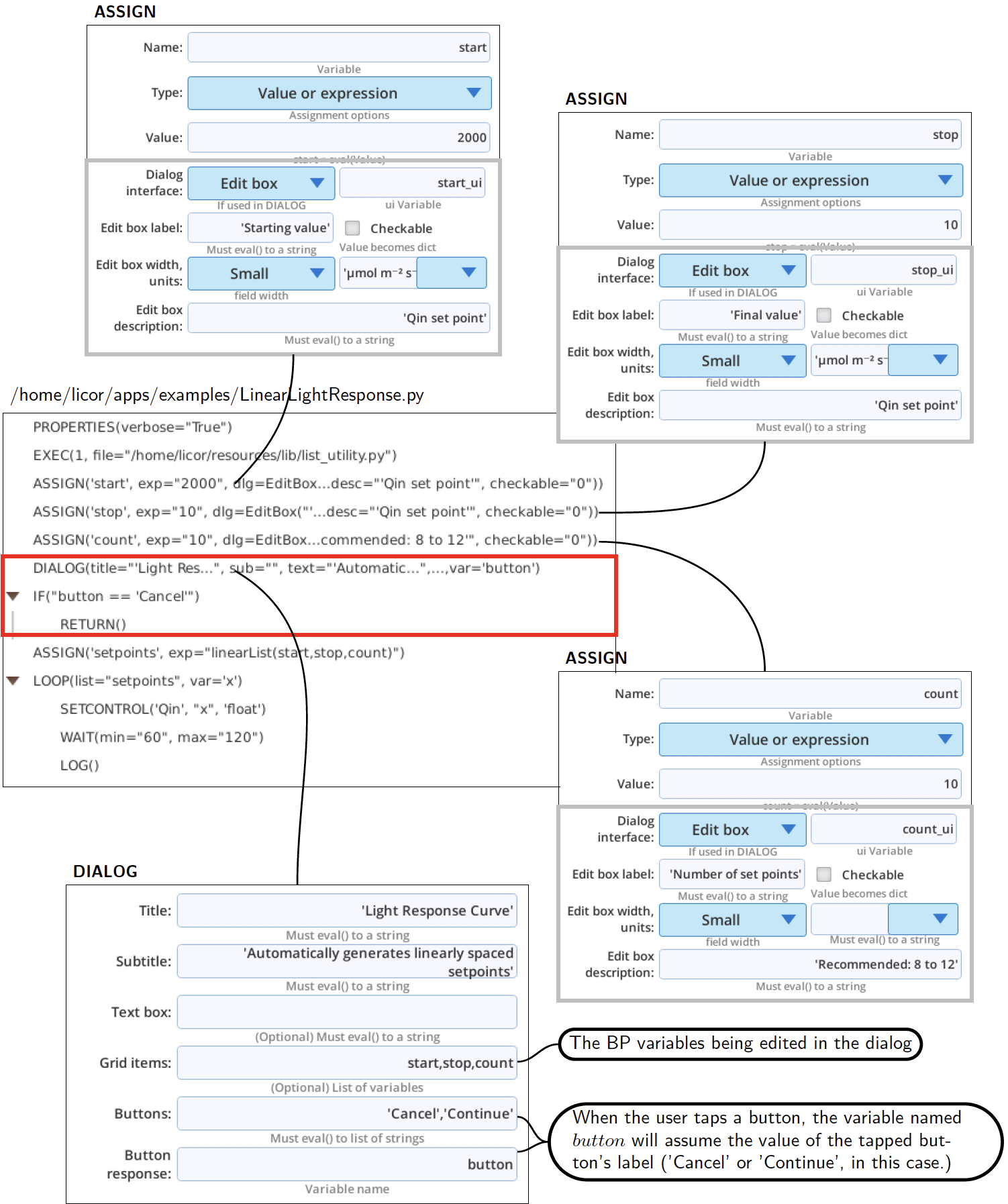
How to make the BP in Figure 12‑17 produce the dialog in Figure 12‑18 is shown in Figure 12‑19, with the program additions shown in the red box. We put the DIALOG step after count is assigned, but before setpoints is computed, since that uses the potentially edited values. We also are handling the Cancel button by IF and RETURN steps. To make start, stop, and count appear in the dialog, they are a) listed in Grid items in the DIALOG setup, and b) they have interfaces specified in their ASSIGN statements.
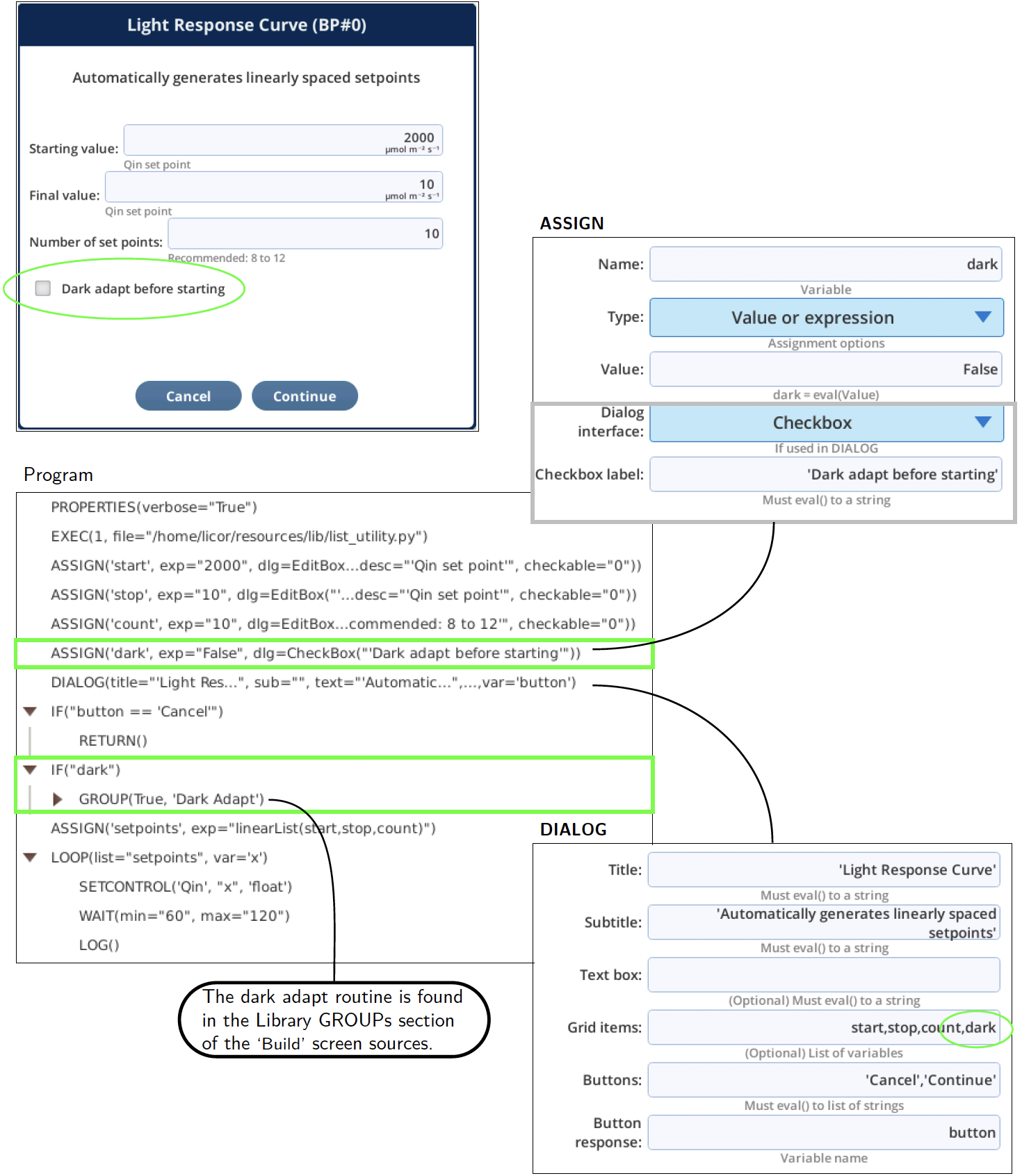
An exercise, let's add a "dark adapt" feature to this program. It's an on/off sort of thing, so would lend itself well to a check box in the dialog and a Boolean variable in the program. Figure 12‑20 illustrates one way to accomplish this:
- Add a variable dark (upper green box), and ASSIGN it to False. Give it a check box interface.
- Add dark to the list of editable items in DIALOG. Put it last if you want it at the bottom of the edit items in the dialog.
- Add some code (lower green box) to perform a dark adaption if dark has been set to True. (We're ignoring the details of what exactly is in the Dark Adapt GROUP in this example).
For more on using DIALOG, see DIALOG.