Measuring the subsample loop flow rate
Follow this procedure if you wish to have a more precise measurement of the subsample flow rate. See Mass balance in an open system for more details.
- Ensure the aquatic chamber pump is set at the speed you will use for measurements.
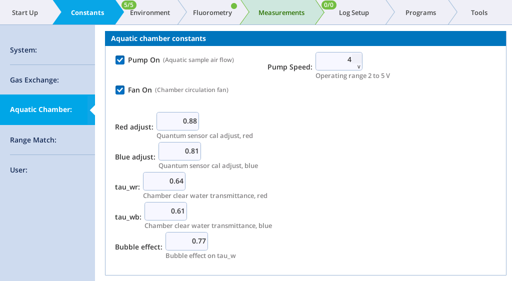
- Pump speed in the aquatic chamber is set via a control voltage under Constants > Aquatic Chamber > Pump Speed. The factory default value for this is 4 VDC. It can be set between 2 and 5 VDC.
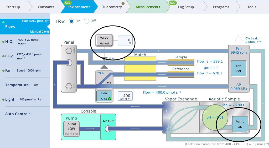
- Turn the aquatic chamber pump on (Environment > Flow). Set the chamber overpressure to off (Environment > Flow Valve = Manual and 0%).
- Fill the chamber with a volume of water comparable to your typical measurement sample volume. Insert the top plug.
- 15 mL is the nominal sample volume.
Note: Ensure that the chamber fill plug is in place. The chamber needs to be sealed and leak free for this test.
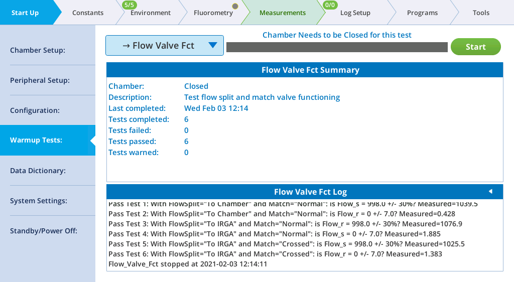
- Run the Flow Valve Fct test under Start Up > Warmup Tests.
- Set the instrument flow rate (Environment > Flow) to 800 µmol s-1.
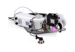
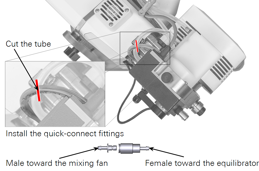
- Using a sharp knife or clippers, cut the tube that connects the water vapor equilibrator to the mixing fan volume.
- This tube connects to the hosebarb labeled 2 on the side of the water vapor equilibrator.
- Install quick connect fittings (300-07124 and 300-07125 in the spares kit) on the tube
- Connect the barbed end of the male fitting to the mixing fan side of the tube and the female fitting to the equilibrator side of the tube.
- Separate the connectors.
- Seal the end of the tube coming from the mixing fan volume with a piece of tape or just cover it with your finger. Leave the tube coming from the water vapor equilibrator vented to the atmosphere.
- Observe Flow_s reported on the flow control screen (Environment > Flow).
- Ensure that it is reporting a value above 300 µmol s-1. If not, make sure the tube from the mixing fan is sealed. If the tube is sealed and Flow_s is less than 300 µmol s-1, increase the flow rate a little at a time until the flow rate exceeds 300 µmol s-1.
- Observe the leak rate reported on the flow control screen.
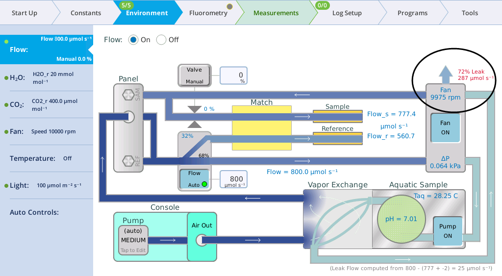
- The reported leak rate (in µmol s-1) is the flow rate through the subsample loop of the aquatic chamber. This value is based on an internal calibration between Flow and Flow_s and gives a good estimate of the subsample flow rate (within ~3% compared to an independent measurement) when Flow_s is greater than 300 µmol s-1.
- Note that the absolute reading reported for Flow_s is uncalibrated and the sensor suffers significant uncertainties with slight pressure pulsations. Do not rely on its reported value to estimate the subsample flow rate.
- Reconnect the fittings on the tubes.