Custom chamber adapter
Installing the chamber adapter
See Removing a chamber to detach a chamber.
- Install the chamber adapter.
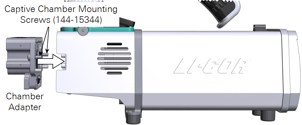
- Tighten the screws snugly—until they are tight and then just a little bit more. Reinstall the connector cover.
Connecting the auxiliary power cable
If you are using the auxiliary power cable, remove the connector cover from the custom chamber interface.

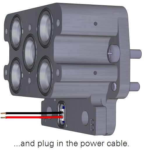
Set the screws and cover aside, where they won't get lost. The power supply cable simply plugs in. Connect the leads to your mixing fan (or whatever it is powering). The red lead is positive (+) and the black is ground (-).
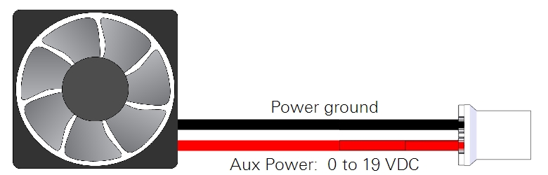
The auxiliary power is turned on or off in the LI-6800 interface under Start Up > Peripheral Setup > Head Light Source > AuxPower. Power can be 0 to 19 VDC.
Connecting to a custom chamber
A custom chamber can connect directly to the custom chamber interface by one of two methods: direct mount or tubing.
Flush mount
The LI-6800 sensor head can be in any orientation when directly mounted to a chamber. The chamber interface mounts directly to a flat surface. After machining the ports and mounting holes in the custom chamber, connect it to the LI-6800 head using 6 panhead screws (part number 150-14476). Be sure that each port on the chamber adapter has an O-ring. Use the Custom chamber template as a guide to create the interface on your chamber.
Tubing mount
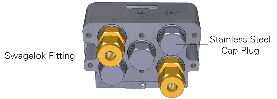
Tubing can be used to connect to the chamber when the direct mount is not suitable. With tubing, you need two ports on the custom chamber—air in and air out—to be fit with Swagelok fittings. The remaining three ports should be sealed with stainless steel caps.
You can use the ¼" Swagelok fittings with the included Bev-a-line tubing, or the 3/8" Swagelok fittings with user-supplied tubing. In either case, you'll need to connect the tubing to the chamber. We recommend hose barbs or Swagelok fittings. The Elbow connections from the spares kit are compatible with the ¼" tubing, however, we recommend using vinyl ferrule sets on the Bev-a-line tubing, rather than steel or brass.
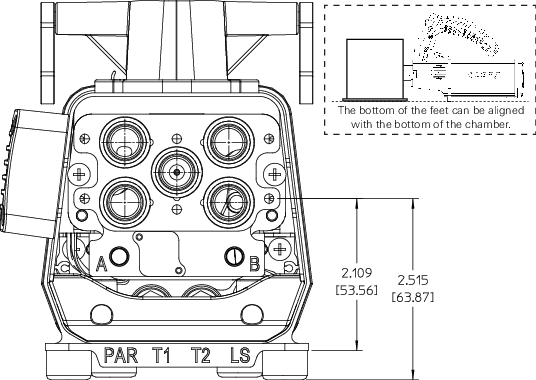
Flow and mixing indicators
The adapter is marked to indicate the function of each port. The meaning of each marking is indicated below.
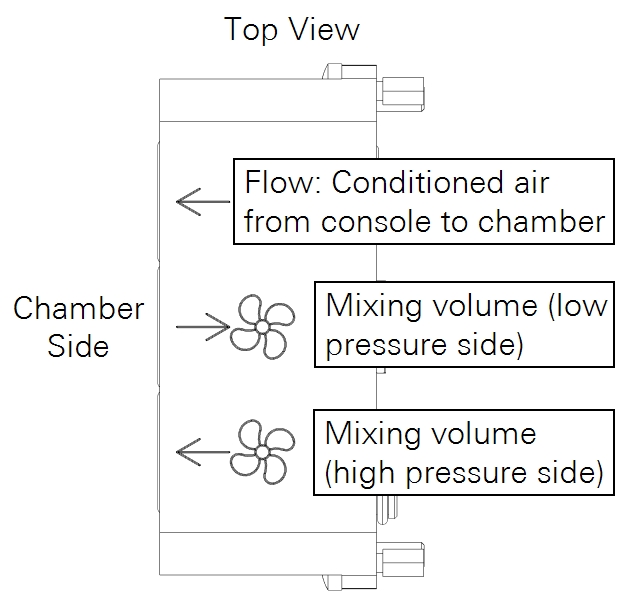
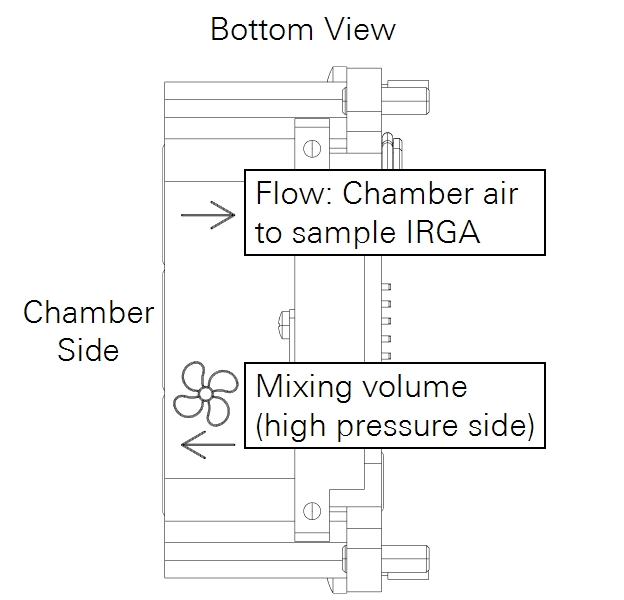
The following diagrams can be used as templates to determine drilling locations on a custom chamber.