Installing the fluorometer chamber
Here we provide basic operating instructions for the 6800-01A fluorometer, starting with installation instructions. See Removing a chamber to detach a chamber.
Printable PDF: Installing the fluorometer chamber
(6800_InstallGuide_Fluorometer_16140.pdf)
Download this content as a pdf that can be saved to your computer or printed.
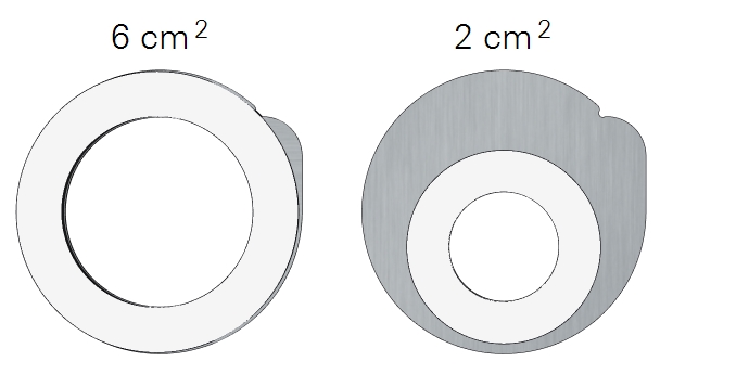
The 6800-01A fluorometer features removable chamber apertures with 6 cm2 and 2 cm2 areas.
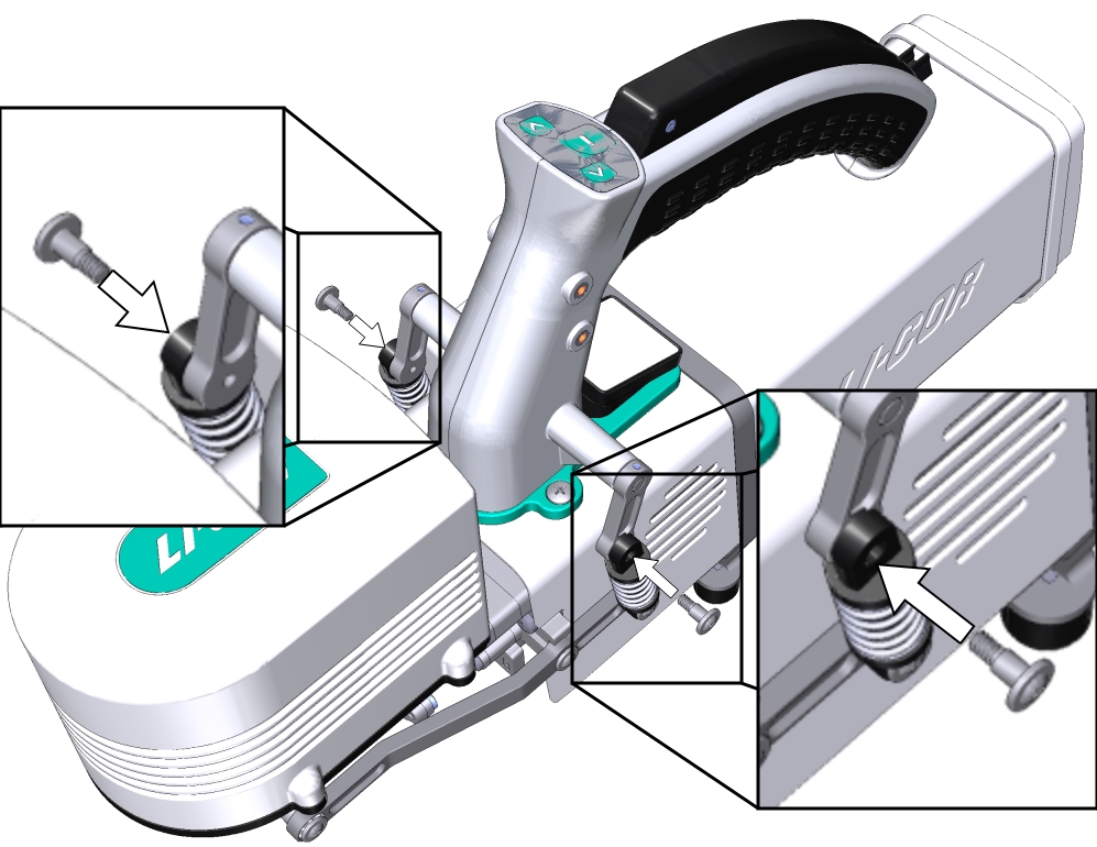
- Hold the fluorometer chamber in position, with the spring that is closest to the cooling fan facing up toward the handle and the cable inside the lever, and tighten the two captive chamber screws.
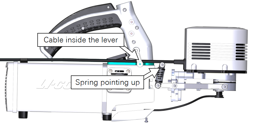
- Make them snug—turn each screw until it stops, and then about ¼ turn more. If you have a torque screwdriver, tighten them to 2.5 N·m (22 inch lbs).
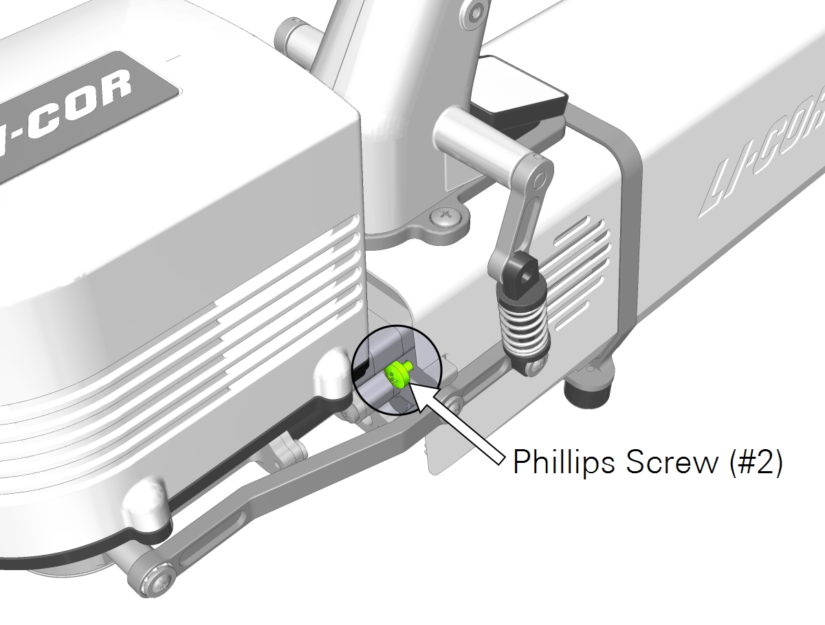
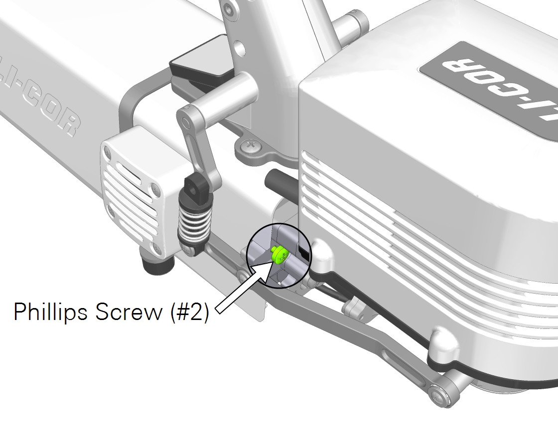
- Caution: You must use the captive chamber screws (part number 144‑15344) to install the chamber. Other screws will cause leaks and problems with the mixing fan, even if they seem to fit.
- Install the chamber latch screws.
- With the latch in the parked position, tighten the screws (part number 146-14474) until they are snug. If you have a torque screwdriver, tighten them to 1.1 N·m (9.4 inch lbs). Double check the tightness of each screw.
- If you unplugged the light sensor cable, install the light sensor connector to the connection labeled PAR.
- Connect the leaf temperature thermocouple cable to the connection labeled T1 or T2.
- Install the connector cover.
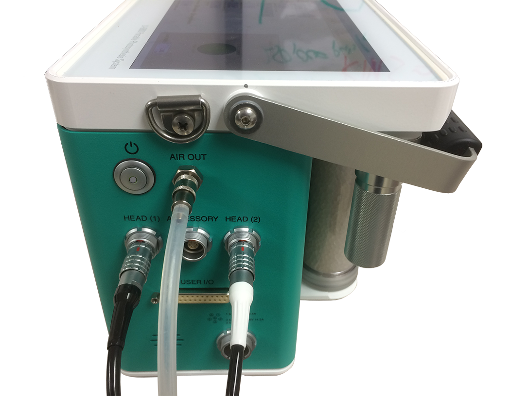
- Plug the Fluorometer cable connector into the console.
- The fluorometer cable (with the white strain relief) and head cable can be plugged into either the Head (1) or Head (2) connector. The connectors are interchangeable.
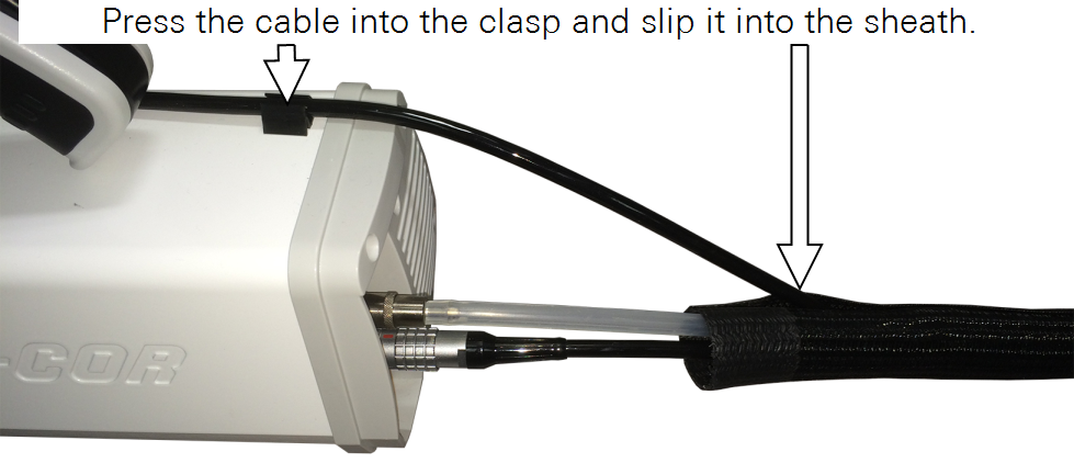
- Slip the cable into the head cable bundle and press the cable into the clasp.
- Power the instrument back on.
- Check to see that the chamber is recognized under Constants > System Constants > ChType.
- Run the leak test under Start up > System Tests > Chamber Leak.
Using apertures
The 6800-01A fluorometer includes removable chamber apertures that allow you to reduce the leaf area. Two aperture sets are available, providing areas of 6 cm2 and 2 cm2. The inside surfaces of the aperture are coated with a black light-absorbing surface. Do not damage the coating.
White advanced polymer gaskets are installed on the chamber prior to shipping. Foam gaskets are included in the accessories kit (black and white). The white gaskets are for the upper aperture; the black gaskets are for the lower aperture.
Points to remember
- Top and bottom apertures must be the same size. For example, do not use the 6 cm2 upper aperture with the 2 cm2 lower aperture.
- When you install apertures, you'll need to select the correct aperture in the software in order to use the correct leaf area and other parameters in computations. You can correct the leaf area and recompute your data later, but it is always a good idea to get the settings right from the outset.
Apertures press into the chamber and are held in place by friction from the O-ring.
- Remove both upper and lower apertures.
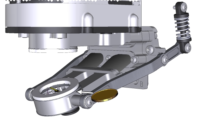
- Use a coin to pop out each aperture.
- Install the apertures.
- Align the key in the aperture with the chamber opening and press it into place. If using foam gaskets, the aperture with the white gasket goes into the upper chamber; the aperture with the black gasket goes into the lower chamber.
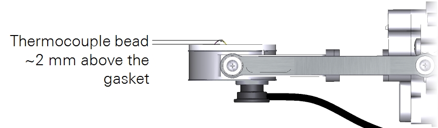
- Install the leaf temperature thermocouple.
- The tip of the thermocouple should make contact with a leaf in the chamber and should not be in contact with the aperture.
- Plug the thermocouple connector into the T1 or T2 connector on the head.
- Power on the LI-6800 and let it warm up.
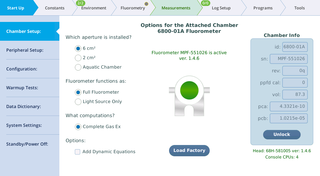
- Select the aperture size.
- Even though the chamber itself is recognized by the LI-6800, the apertures are not. Under Start Up > Chambers, you'll see options for the chamber aperture. Select the aperture size of 6 cm2, 2 cm2, or Aquatic Chamber.