Connecting an external air supply
Two air inlets are available to introduce your own conditioned air supply if you do not want to start with ambient air. The difference between the inlets is:
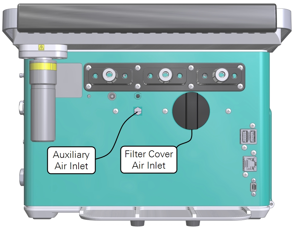
- The Auxiliary Air Inlet between the H2O Scrub and H2O Add columns on the console, is plumbed downstream of the pump and the CO2 scrub column (see Figure 1‑2).
- The Filter Cover Air Inlet is a threaded connection on the bottom of the filter cover. The cover is between the H2O Add and CO2 Scrub columns.
Important: If using an oxygen concentration different from ambient (21%), be sure to change this setting in the Constants before taking measurements (see System constants).
The software considerations when using an external air supply are described in Extended control range.
Using the auxiliary air inlet
To use the Auxiliary Air Inlet, attach an air supply. There is no pump so the connected source will need to provide the correct pressure and flow rate. There is no filter in the air stream because this inlet is downstream of the filter. Use clean air or provide your own filter to keep dust out of the plumbing.
- Remove the plug and set it aside for safekeeping.
- Install a hosebarb in the Auxiliary Air Inlet.
- The threads are M5 (metric units) or approximately 10-32 (imperial units). The hosebarb can be purchased from LI-COR (part number 300-15712) or another supplier.
- Connect the air supply and pressurize the system.
- The maximum flow rate is 2.5 lpm and maximum pressure is 28 kPa. The LI-6800 pump will not affect the flow rate because the air inlet is downstream of the pump.
Warning: Do not exceed the ratings on the auxiliary air inlet. Maximum flow rate of 2.5 liters per minute. Maximum pressure of 28 kPa.
Using the filter cover air inlet
The filter cover air inlet is threaded into the air inlet cap. This inlet is upstream of the pump and CO2 scrub column, so air that is provided this way can be scrubbed of CO2 and pumped by the LI-6800 pump.
- Install a hosebarb on the air inlet.
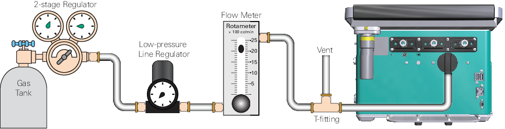
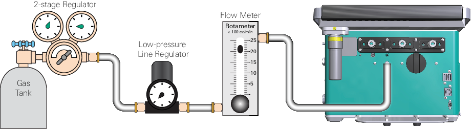
- Assemble a t-fitting with one tube coming from the air supply, one tube going to the air inlet, and the other tube venting to the ambient air (see Figure 2‑5). Put about 10 to 15 cm of tubing on the vent. This will prevent ambient air from diffusing up the vent, which can happen at low flow rates.

- Install the air inlet on the console, then reinstall the columns.
- Turn on the air supply.
- Your air supply should have 2.5 to 3 lpm of flow.
- Use the LI-6800 pump to control the flow rate.