Mass balance derivation using a two-compartment model
A more careful analysis leads to this conclusion: when fan speed is high (10,000 rpm or greater) and there is little leakage (< 100 µmol s-1) in the leaf chamber, the single volume analysis works just fine. At higher leak rates, especially combined with lower fan speeds (below 10,0000 rpm), then the single volume analysis starts to break down.
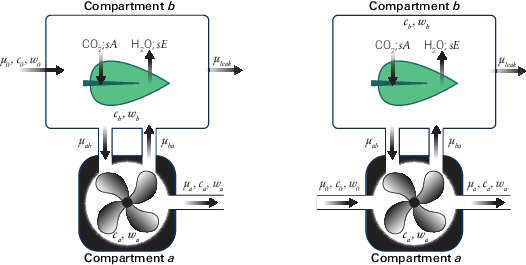
In the original 6800-01 and 6800-12 chambers, the incoming and outgoing flow rates were both from compartment a. Deriving the mass balance for that configuration leads to a small influence of leaks on the concentrations measured by the sample gas analyzer, leading to a correction implemented in Bluestem v1.1. The 6800-01 and 6800-12 chambers have been re-designed (and renamed to 6800-01A and 6800-12A) to route the incoming flow directly to the chamber, which eliminates the need for a leak correction.
The mass balance equations provided here are assuming a two-compartment system where compartment a is the mixing fan volume and compartment b is the leaf volume (Figure 9‑77). In the diagram and subsequent equation set, c represents CO2 concentration, w represents H2O concentration, and μ represents flow rate. Subscripts on flow rates denote the 'to' location followed by the 'from' location. For example, μab is the flow to compartment a (the subscript a) from compartment b (the subscript b).
Derivation of mass-balance equations for chambers
This section describes the computations used for the 6800-01A, 6800-12A, 6800-13, 6800-17, 6800-24 and custom chamber interface.
The mass balance equations describing compartment a

and compartment b
9‑114

can be combined to solve for the sample IRGA flow rate µa

H2O analysis
Behavior of water vapor with respect to time in compartment a

And compartment b

Assuming steady-state conditions (dW/dt = 0), equation 9‑117 can be solved for Wb:
9‑118

The solution for Wb can be substituted into equation 9‑116 (again, assuming steady-state):

Since µab = µba + µoa (equation 9‑113), substitute into equation 9‑119:

Re-arranging and simplifying equation 9‑120:
9‑121

Equation 9‑115 can be used to substituted for µa and the equation solved for sE:
9‑122

It can be shown that the concentrations of compartments a and b are equivalent by substituting equation 9‑113 into equation 9‑116:
9‑123

Re-arranging and canceling yields:
9‑124

CO2 analysis
Behavior of CO2 with respect to time in compartment a

And compartment b

First solve for Cb in equation 9‑126 assuming steady-state conditions (dC/dt = 0)
9‑127

Substitute Cb into equation 9‑125

From equation 9‑113, µab = µba + µa, substitute into 9‑128
9‑129

Which simplifies to

From equation 9‑115, µa = µao + sE - µleak substitute into 9‑130
9‑131

Which can be re—arranged to solve for sA
9‑132

Combining equation 9‑125 with equation 9‑113 yields:
9‑133

which simplifies to:
9‑134

Derivation of mass-balance equations for 6800-01 and 6800-12 chambers
This section describes the computations used for the original 6800-01 Fluorometer and 6800-12 clear-top 3×3 cm chamber.
The mass balance equations describing compartment a

and compartment b
9‑136

can be combined to solve for the sample IRGA flow rate μa
 .
.H2O analysis
Behavior of water vapor with respect to time in compartment a is

and compartment b,
 .
.Assuming steady-state conditions (dw/dt = 0), equation 9‑139 can be solved for wb:
9‑140

The solution for wb can be substituted into equation 9‑138 (again assuming steady-state):

Since µab = µba + μa – μ0 (equation 9‑135), substitute into equation 9‑141
9‑142

9‑143

Equation 9‑137 can be substituted for μa:
9‑144


K can be defined as

Since sE << µba, µleak , K can be approximated as
9‑147

Substituting K into equation 9‑145:
9‑148

9‑149

9‑150

Re-arranging and solving for sE:

9‑151

 can be eliminated


Leaving:
9‑153

CO2 analysis
Behavior of CO2 with respect to time in compartment a

And compartment b

First solve for Cb in equation 9‑155 assuming steady-state conditions (dC/dt = 0)

Substitute Cb into equation 9‑154

From equation 9‑135, µab = µba + μa - μ0, substitute into 9‑157

From equation 9‑137,  substitute into 9‑158

From equation 9‑146, K = µba+sE / µba + sE - µleak substitute into 9‑159
9‑160

Solving for sA yields


9‑161

From equation 9‑152, Kµba - Kµleak - µba can be eliminated, leaving
9‑162

9‑163

9‑164

Calculating Cb
The LI-6800 IRGA is measuring the concentration of compartment a. However, the concentration in a will not be equal to concentration in compartment b, where the leaf is located. To compute intercellular CO2 (Ci), we need to know Cb which can be calculated from combining equations 9‑135 and 9‑156
9‑165

Then substituting equation 9‑137 solved for sE
9‑166

Eliminating the small impact of sE, the resulting equation for Cb is
9‑167

Discussion
This section only applies to the early 6800-01 and 6800-12 chambers. All other chambers do not require a leak correction. In a two compartment model, the gas exchange equations become:


The difference between the flux equations between the one-compartment derivation and this model is the correction factor K which is  , or the mixing fan flow rate divided by the difference between mixing fan flow rate and leak rate. As µba >> µleak, the equation can be simplified to
9‑170

The multiplier M is a chamber-specific multiplier value. The necessity for the multiplier M arises from the different chamber geometry and port sizes of the tubes between the leaf cuvette and the mixing fan volume. In current chambers, M is 2 and 1.5 for the fluorometer and 3×3 cm chambers, respectively.
The parameter µba is also not measured directly by the instrument but must be calculated from the measured parameter fan speed (in RPM, rotations per minute). The amount of flow created by the mixing fan is not linear across the range of rotations per minute applied. Consequently, an empirical fit best describing fan speed vs. air flow was generated.
9‑171

where µba is the flow rate created by the fan in μmol s-1, Fan_RPM is the measured fan rotation rate, a (-6280), b (6.60), and c (1.71E-05) are empirically determined parameters, T is temperature (°C) and P is pressure (kPa).
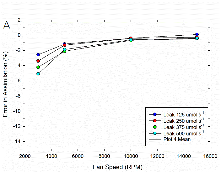
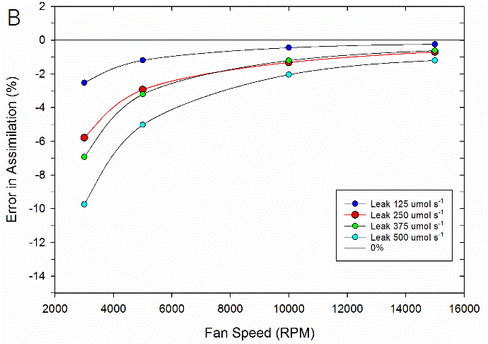
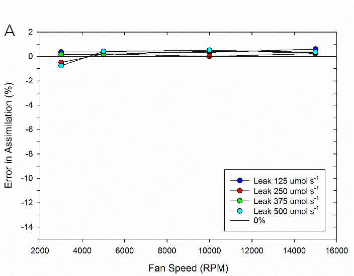
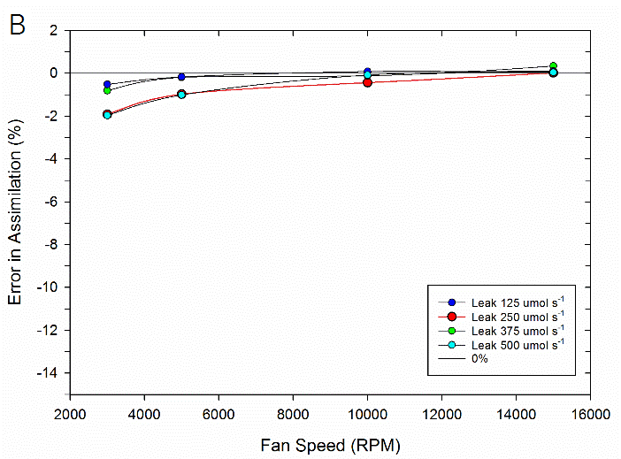
To test the impact of the correction, experimental data were collected on both fluorometer and 3×3 cm chambers. In the experiment, a chamber was sealed containing a mechanical structure that creates a constant flux. Fluxes were recorded first with no chamber leaks and again with measured controlled leak rates. The % error reported is the difference in measured flux between the leak and no-leak situation. Data is shown prior to any correction (Figure 9‑78), after having the correction applied to them (Figure 9‑79, B).
Equations 9‑168 and 9‑169 can also be used to determine where the impacts from leaks on calculated fluxes can become significant. A quick analysis shows that the correction factor K only becomes significant in circumstances of high leak rates AND low mixing fan speeds. For example, at a relatively fast fan speed of 10,000 RPM, a leak of 350 μmol s-1 in the 3×3 cm chamber and 250 μmol s-1 in the fluorometer generates a 1% bias. In contrast, a fan speed of 3000 RPM obtains a 1% bias with smaller leaks, 80 μmol s-1 in the 3×3 cm chamber and a 60 μmol s-1 in the fluorometer.
In summary, the susceptibility of the LI-6800 to chamber leaks will be negligible in most operating conditions. Best measurement practice includes operating at fast fan speeds and preventing significant chamber leaks which can introduce bias into your measurements. Software release 1.1 includes information regarding current leak status as well as the correction factor being applied to assist with avoiding problem areas.