Warmup tests
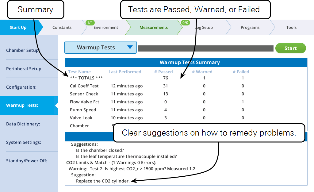
The warmup tests are designed for daily use, to catch errors and faults that might compromise your measurements. If everything passes, you can be reasonably sure (but not guaranteed) that the system is working as expected. Common failures are due to worn out desiccant or an empty CO2 cylinder. Other failures may be simply because a setting or measurement is just outside the expected range, in which case you have to decide if it needs attention or can be ignored. The descriptions below should help you make those decisions.
All of the system tests that rely on flow rate contain a silent test that checks the state of the flow system. ("Silent" means that output is logged only if there is a problem.) If there is problem with flow, the system test is abandoned, and reasons given.
If the issue is a console leak, the following results:
Chamber_Pressure started at 2019-09-25 13:15:34
Overpressure test, Pump=high
*** Fail *** Test 1: Abandoning Test. System Flow Fault.
Suggestion:
Console Flow Leak. Desiccant or Humidifier tube cap loose?
Chamber_Pressure stopped at 2019-09-25 13:15:46
If the issue is unexpectedly low flow, the following results:
Chamber_Pressure started at 2019-09-25 13:18:35
Overpressure test, Pump=high
*** Fail *** Test 1: Abandoning Test. Expected flow > 100. Measured -0.0.
Suggestions:
Is the flow tube from the console firmly connected to the head?
Is the pump functioning?
Chamber_Pressure stopped at 2019-09-25 13:18:46
Cal coeff test
The calibration coefficient test (Cal coeff test) tests each current user calibration setting to see if it falls within an expected range. If a value falls outside that range, it marked as failed. This does not necessarily mean something is wrong, but it does bear further investigation. For example, if a zeroing parameter failed, it is OK if that value is what it really takes to properly zero that sensor, but make sure that the sensor hasn’t been mis-zeroed instead.
Pass Test 1: Cal check: Is oxygen between 2 and 22? Currently=21.0
Pass Test 2: Cal check: Is co2azero between 0.8 and 1.2? Currently=0.90977
Pass Test 3: Cal check: Is co2aspan1 between 0.8 and 1.2? Currently=1.003
Pass Test 4: Cal check: Is co2aspan2 between -0.3 and 0.3? Currently=-0.002
Pass Test 5: Cal check: Is co2bzero between 0.8 and 1.2? Currently=0.911449
Pass Test 6: Cal check: Is co2bspan1 between 0.8 and 1.2? Currently=1.0
Pass Test 7: Cal check: Is co2bspan2 between -0.3 and 0.3? Currently=0.0
Pass Test 8: Cal check: Is h2oazero between 0.8 and 1.2? Currently=1.01078
Pass Test 9: Cal check: Is h2oaspan1 between 0.8 and 1.2? Currently=1.01456
Pass Test 10: Cal check: Is h2oaspan2 between -0.3 and 0.3? Currently=-0.116034
Pass Test 11: Cal check: Is h2obzero between 0.8 and 1.2? Currently=0.988944
Pass Test 12: Cal check: Is h2obspan1 between 0.8 and 1.2? Currently=1.02657
Pass Test 13: Cal check: Is h2obspan2 between -0.3 and 0.3? Currently=-0.263223
Pass Test 14: Cal check: Is tazero between -0.5 and 0.5? Currently=-0.223923
Pass Test 15: Cal check: Is tbzero between -0.5 and 0.5? Currently=-0.174402
Pass Test 16: Cal check: Is flowmeterzero between 0.5 and 1.4? Currently=0.991608
Pass Test 17: Cal check: Is flowazero between 0 and 0.8? Currently=0.39242
Pass Test 18: Cal check: Is flowbzero between 0 and 0.8? Currently=0.22801
Pass Test 19: Cal check: Is chamberpressurezero between 2 and 3? Currently=2.55412
Pass Test 20: Cal check: Is ssa_ref between 20000 and 55000? Currently=34092.0
Pass Test 21: Cal check: Is ssb_ref between 20000 and 55000? Currently=33927.5
Pass Test 22: Chamber Info: Is pca = 0? Currently=0
Pass Test 23: Chamber Info: Is pcb = 0? Currently=0
h2oazero, h2obzero, co2azero, co2bzero
Zero values for the IRGAs (a = sample, b = reference) are typically between 0.8 and 1.2. These values are set from the calibration menu, either by flowing zero air through the appropriate cell and pressing a button, or by direct editing. If one of them is out of range, visit the calibration menu and make sure the zero was properly done. If you need to redo the zero, see Setting the IRGA zeros.
Example: suggestion when warning about co2azero:
Verify that CO2_s is properly zeroed.
h2oaspan1, h2obspan1, co2aspan1, co2bspan1
Span 1 values for the IRGAs (a = sample, b = reference) are typically between 0.9 and 1.2, but expect them to be very close to 1.0. Departures from 1.0 may be real, or may be due to spanning at an inappropriate time, or with a gas that is not actually at the assumed concentration (or for H2O, an issue with the LI-610 dew point generator: lack of water, overpressure, etc.) These values are set from the calibration menu, either by flowing calibrated air through the appropriate cell and pressing a button, or by direct editing. Hint: manually setting these values to 1.0 can sometimes be the best action for span related issues. If you do this, also set the associated span 2 value (next) to 0.
Example: suggestion when warning about co2aspan:
Verify that CO2_s is properly spanned.
h2oaspan2, h2obspan2, co2aspan2, co2bspan2
Span 2 values for the IRGAs (a = sample, b = reference) are typically between -0.3 and +0.3. A value of 0 means there is no secondary span. Values outside the expected range should be treated with suspicion, and are likely due to improper calibration. These values are set from the calibration menu, either by flowing calibrated air through the appropriate cell and pressing a button, or by direct editing. Hint: manually setting these values to 0 can sometimes be the best action for span related issues.
Example: suggestion when warning about co2aspan2:
Verify that CO2_s is properly spanned.
tazero, tbzero
These are offsets to correct the IRGA exhaust temperature sensors (a = sample, b = reference) to the IRGA temperature thermistor (Tirga). These are typically between -0.5 and +0.5 °C. The test for an appropriate setting is to compare Ts and Tr - they should be quite close under stable temperature conditions and similar flows going though the cells. These temperatures can be matched in software version 1.4 and above, by using the BP (background program) named ZeroTaTb.py found in /home/licor/apps/tech/.
Example: suggestions when warning about tazero:
Verify that sample cell temp Ts is close to Tirga.
Use the apps/tech/ZeroTaTb.py BP to make them match.
ssa_ref, ssb_ref
These values are factory-set reference readings used to compute the IRGA cell signal strength SS_s and SS_r. (ssa_ref is for sample, and ssb_ref used for reference). Expected values are between 22000 and 55000.
Example: suggestion when warning about ssa ref
This only affects sample cell signal strength SS_s.
chamberpressurezero
This value is the signal from the chamber overpressure sensor when overpressure is 0. The expected value is between 2 and 3 V. This can be set in the flow zeroing calibration screen. A value out of that range would indicate that zeroing occurred when it should not have (there was overpressure), or perhaps a sensor fault.
Suggestion when warning about chamberpressurezero:
Verify that chamber pressure is properly zeroed.
flowmeterzero
This value is the offset of the main flow meter. Expected value is between 0.5 and 1.4 V. This can be set in the flow zeroing calibration screen. A value out of that range would indicate that zeroing occurred when it should not have (there was flow), or a sensor fault.
Suggestion when warning about flowmeterzero:
Verify that Flow is properly zeroed.
flowazero, flowbzero
These are offset signals to zero the IRGA exhaust flow sensors (a = sample, b = reference). The expected range is between 0 and 0.8 V. These can be set in the Flow/Pressure calibration screen. A value out of that range would indicate that zeroing occurred when it should not have (there was flow), or a sensor fault.
Example: suggestion when warning about flowazero:
Verify that Flow_s is properly zeroed.
pca, pcb
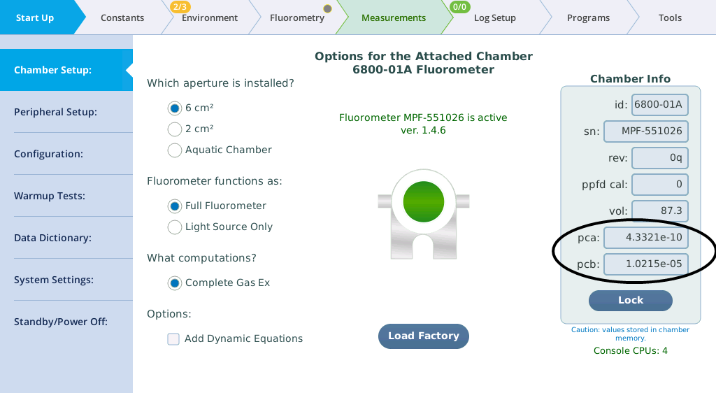
These values are used to correct chamber overpressure for fan speed and flow rate in chambers that have apertures (and a modified internal flow path). The expected values are based on what chamber type the system thinks is attached. The values are available on the Chamber Setup screen.
| Chamber | pca | pcb |
|---|---|---|
| 6800-01 Fluorometer | 0 | 0 |
| 6800-01A Fluorometer | 4.3321E-10 | 1.0215E-5 |
| 6800-12 3×3 cm Chamber | 0 | 0 |
| 6800-12A 3×3 cm Chamber | 2.6520E-10 | 1.3064E-5 |
| 6800-13 6×6 cm Chamber | 4.3998E-11 | 1.4792E-5 |
| 6800-17 Small Plant | 0 | 0 |
| 6800-19 Custom | 0 | 0 |
Suggestion when warning about pca or pcb:
Set proper value in Chamber Setup.
Details for each chamber type are given in Chamber info.
Oxygen
This test checks the system constant for a reasonable value for oxygen (2 to 22%). The value is settable in system constants.
Suggestion when warning about Oxygen:
Set as needed in system constants.
Sensor check
This test checks some sensors for proper zero, and some other sensors and settings for reasonable values.
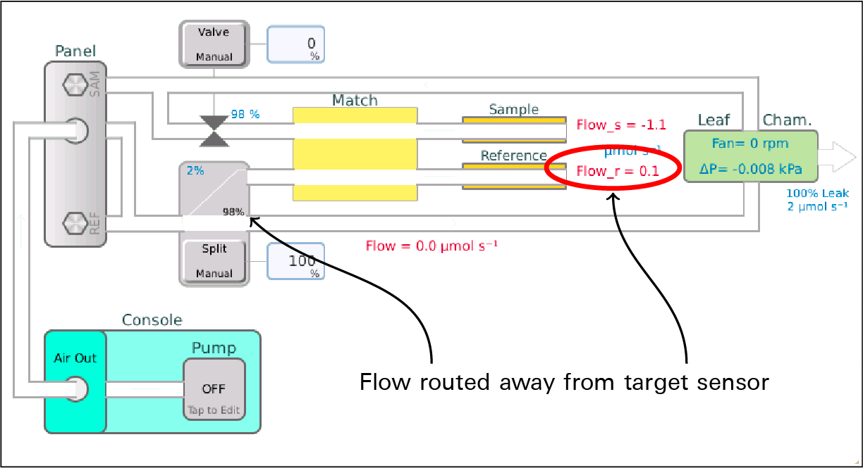
With the pump off, mixing fan off, and temp control off, all flow (if there is any) is routed to the chamber, and after a 10 second wait, the reference cell IRGA flow is tested for zero.
Pass Test 1: Is Flow_r within 5 of zero? Measured=0.1umol s-1
Flow is then routed to the Reference IRGA, and after a 5 second wait, the following zeros are checked:
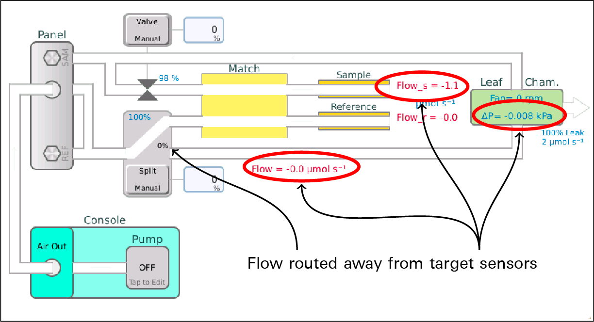
Pass Test 2: Is Flow within 2 of zero? Measured=-0.2umol s-1
Pass Test 3: Is Pchamber within 0.05 of zero? Measured=0.0008kPa
Pass Test 4: Is Flow_s within 5 of zero? Measured=-0.4umol s-1
Falling outside of the stated tolerance is a warning. It becomes an error if the sensor is out by more than 4 times the tolerance. The remedy is always:
Zero the sensor
Tests 5 and 6 check that the IRGA's internal temperatures are being controlled to 30 °C. They should be correct by default, but they are changeable through alternative interfaces.
Pass Test 5: IRGA temperature control on? Setting= on
Pass Test 6: IRGA temperature control on target (30.0)? Measured 30.0
A failure on either of these IRGA control temperature tests is an error, with the suggestions:
Try restarting the system.
Contact LI-COR.
A sanity check on temperature sensors follows. At least one leaf temperature sensor is expected (unless configured for the soil or aquatic chamber). Any other failure in this group would indicate a failed sensor, or that you are in conditions out of the operating range of the instrument.
Pass Test 7: At least one Leaf temp sensor? Tleaf=27.33, Tleaf2=999.9
Pass Test 8: Is Tchamber between -5C and 60C? 27.51
Pass Test 9: Is Txchg between -5C and 60C? 25.82
Pass Test 10: Is Ta between -5C and 60C? 27.53
Pass Test 11: Is Tb between -5C and 60C? 27.57
Pass Test 12: Is Tirga_block between -5C and 60C? 27.74
Pass Test 13: Are Ta, Tb, and Tirga_block within 0.5C? 0.21
A failure on Test 7 is a warning, with the suggestion:
Plug in a working leaf temperature thermocouple, or use energy balance.
A failure on Tests 8 through 12 is an error, with the suggestion:
Contact LI-COR.
A failure on Test 13 (Ta, Tb, and Tirga block matching) is a warning, with the suggestion:
Use the apps/tech/ZeroTaTb.py BP to make them match.
Flow valve fct
The flow valve functionality test checks for basic functionality of the match/flow split control unit by doing a simple sequence and looking at the flow meters:
- With all the air routed to the chamber and the match valve normal, measure Flow.
- That value becomes the target for this test. Flow_s (if the chamber is closed and not leaking badly) should be within 30% of the target value, and Flow_r would be 0.
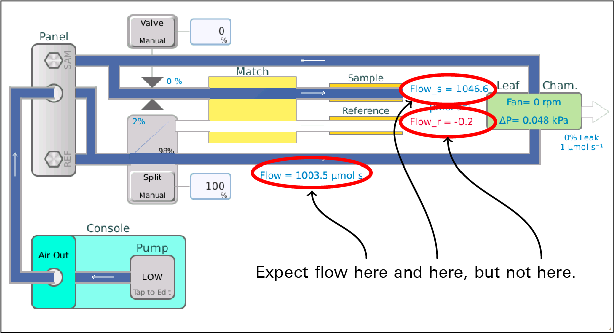
Pass Test 1: With FlowSplit="To Chamber" and Match="Normal": is Flow_s = 1003.5 +/- 30%? Measured=1048.6
Pass Test 2: With FlowSplit="To Chamber" and Match="Normal": is Flow_r = 0 +/- 7.0? Measured=-0.2
- Now route all the flow to the reference cell.
- Flow_r should read close to the target, and Flow_s should be 0.
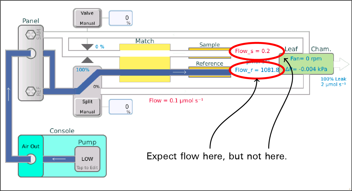
Pass Test 3: With FlowSplit="To IRGA" and Match="Normal": is Flow_r = 1003.5 +/- 30%? Measured=1081.8
Pass Test 4: With FlowSplit="To IRGA" and Match="Normal": is Flow_s = 0 +/- 7.0? Measured=0.2
- With all the flow still going to the IRGAS, route it to the sample.
- Flow_s should be close to the target, and Flow_r should be 0.
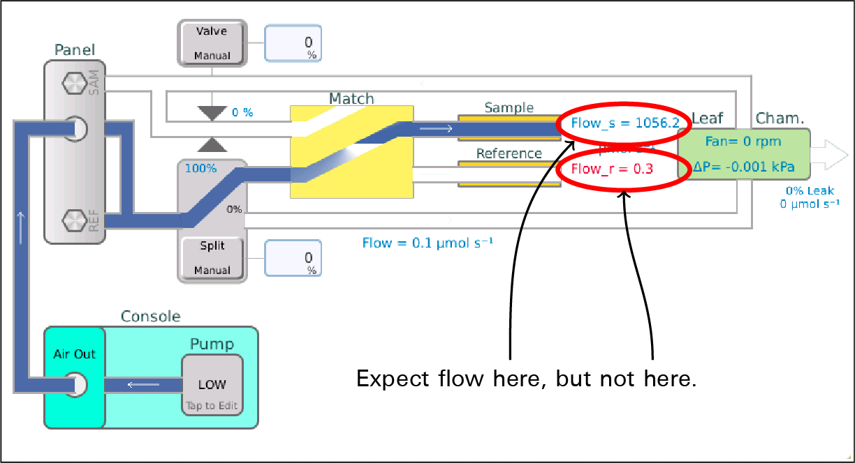
Pass Test 5: With FlowSplit="To IRGA" and Match="Crossed": is Flow_s = 1003.5 +/- 30%? Measured=1056.2
Pass Test 6: With FlowSplit="To IRGA" and Match="Crossed": is Flow_r = 0 +/- 7.0? Measured=0.3
If a flow rate is off by more than 30% of expected, the following are suggested:
Determine why the flow is not getting to the expected location.
Worst case is a nonfunctioning valve, which would require LI-COR service.
On failures of the no-flow sensor being off by more than 7 µmol s-1, the following are suggested:
This could be a flow zeroing issue (refer to 'Sensor Check' test).
This could a leaking valve issue (refer to the 'Valve Leak' test).
Pump speed
The pump speed checks that the 4 active pump settings (minimum through high) generate the flow expected, within 20%, adjusting for ambient pressure.
Pass Test 1: At Pump=minimum, Flow expected to be within 20% of 685.0? Measured 655.265 (-4.3% low)
Pass Test 2: At Pump=low, Flow expected to be within 20% of 1028.0? Measured 981.342 (-4.5% low)
Pass Test 3: At Pump=medium, Flow expected to be within 20% of 1370.0? Measured 1325.79 (-3.2% low)
Pass Test 4: At Pump=high, Flow expected to be within 20% of 1713.0? Measured 1654.25 (-3.4% low)
A failure is an error, with these suggestions:
Check for leaks in the flow connections between the console and sensor head.
If it is a pump calibration issue, run the BP apps/tech/CalibratePumpSettings.py.
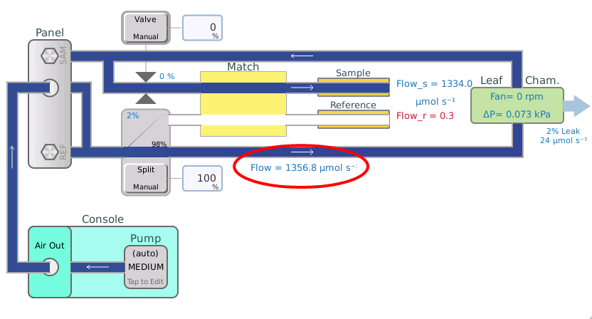
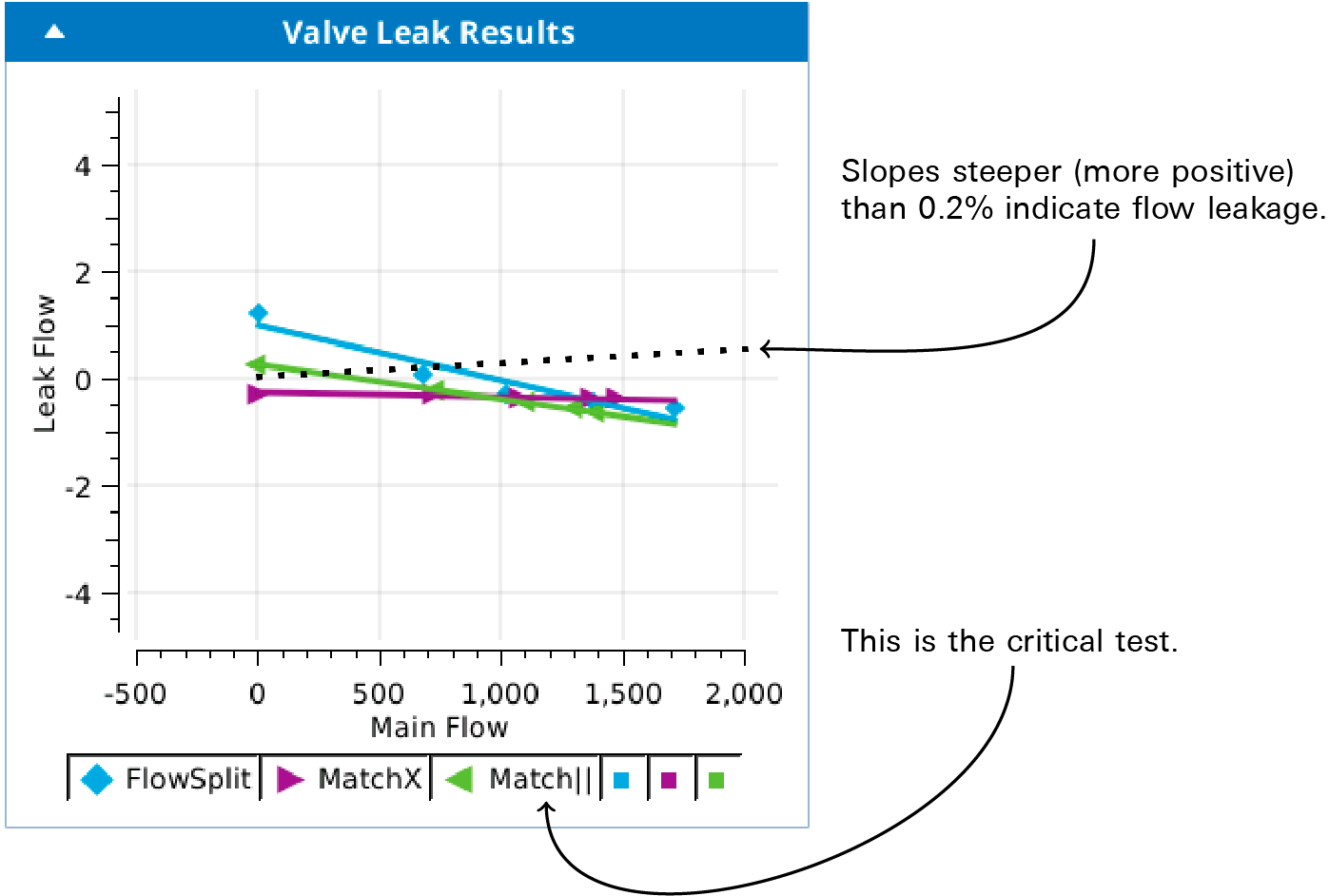
Valve leak
The valve leak test does a systematic leak detection test on the flow split / match valve. The methodology is to put the valve into a particular state, then ramp the pump from low to high, and look for any trends up in the flow meters that should NOT be getting any flow. Specifically, on a plot of leaked flow plotted as function of main flow, we are looking for slopes of less than 0.2%. More than that might be a leak.
Step 1 has all the flow going to the chamber, with the match valve crossed to return air from the chamber is vented to the case. Flow_s should be getting nothing.
Step 2 routes all flow to IRGA and Flow_s. Flow_r would be getting nothing.
Step 3 routes all flow to IRGA and Flow_r. Flow_s should be getting nothing.
Step 1/3 (Flow Split Valve): All flow to chamber, leaks to Flow_s
Pass Test 1: Is Flow split valve leak response slope < 0.002 ? Measured -0.001
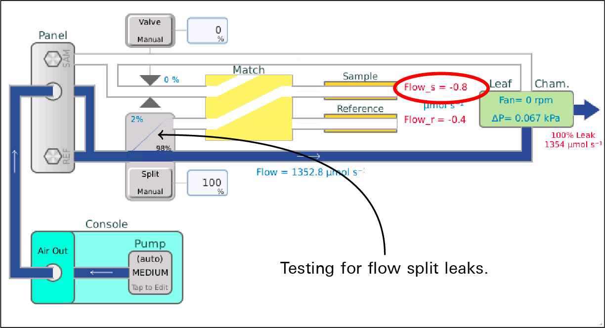
Step 2/3 (Match Crossed): All flow to Flow_s, leaks to Flow_r
Pass Test 2: Is Match X valve leak response slope < 0.002 ? Measured -0.0
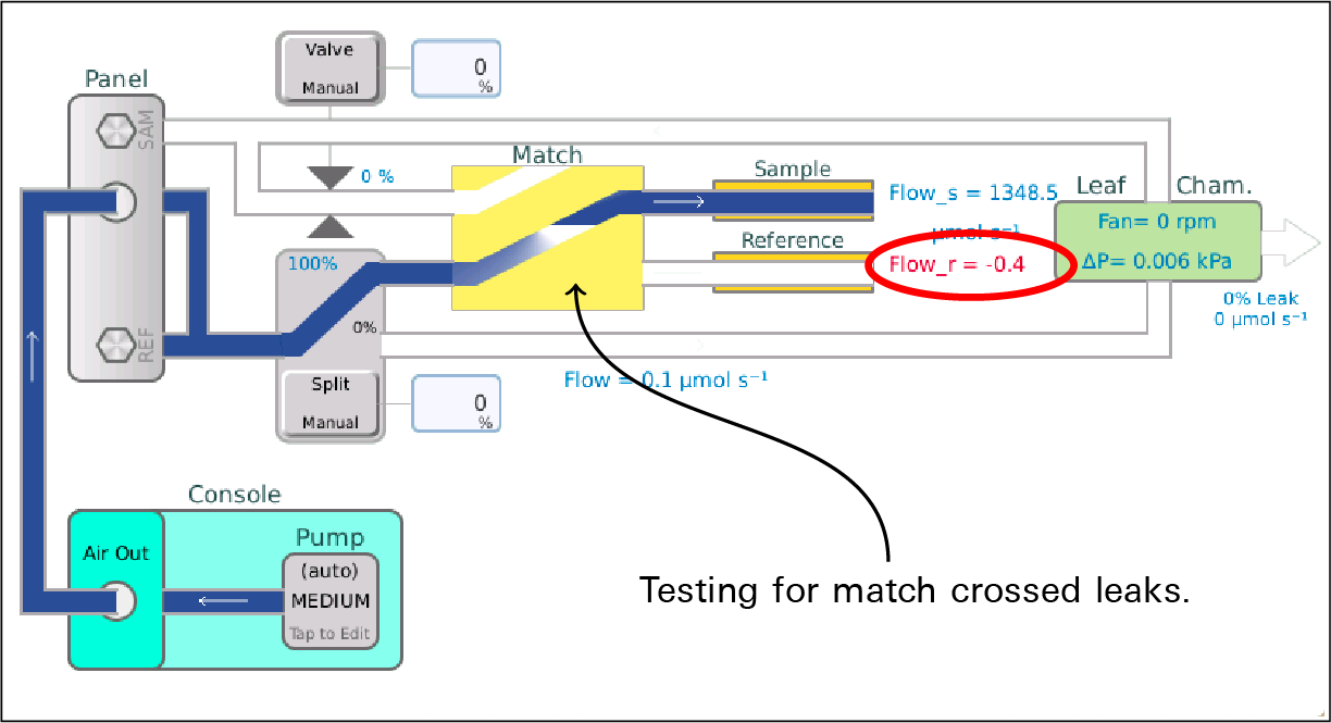
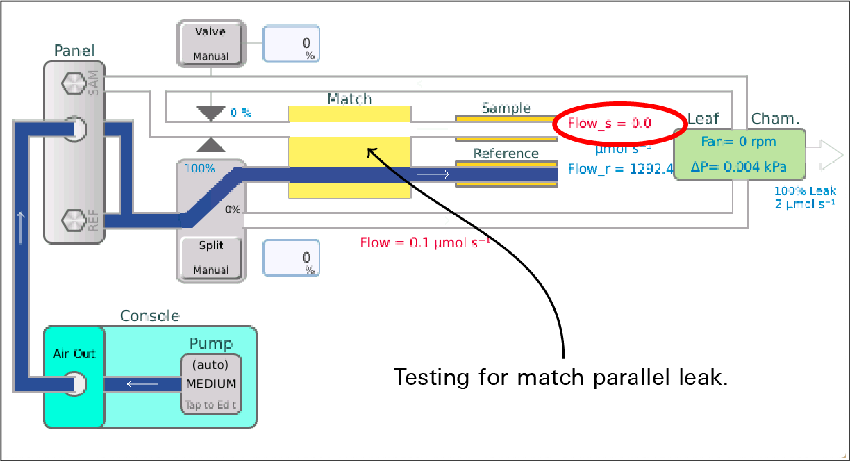
Step 3/3: Match Straight: All flow to Flow_r, leaks to Flow_s
Pass Test 3: Is Match || valve leak response slope < 0.002 ? Measured -0.001
Failures of the first two tests are warnings, since they don't really compromise measurement integrity. The suggestions are:
Slight leaks in this flow configuration do not compromise measurements.
Fixing this issue requires LI-COR service.
A failure of the last test is serious, and an error. The suggestions are:
Leaks with the match valve in normal position DO compromise measurements.
Fixing this issue requires LI-COR service.
A leak in the flow split (step 1) wouldn't matter for normal operation, and a leak while matching (step 2) wouldn't matter, since the valve is not fully closed, but directing air to both cells. However, the critical one is the third test, with the match valve in normal operating position. A leak here represents potential cross contamination between cells, which will corrupt your measurement. A leak in step 3 needs to be dealt with.
Chamber pressure
The chamber pressure test attempts to hold the chamber overpressure at 0.1 kPa with the pump cycling through three flow rates. If there is a chamber leak, the lower the pump speed, the harder it is to hold that high an overpressure. If the issue is not a chamber leak, but a failed pressure control valve, then the test would fail at all pump speeds.
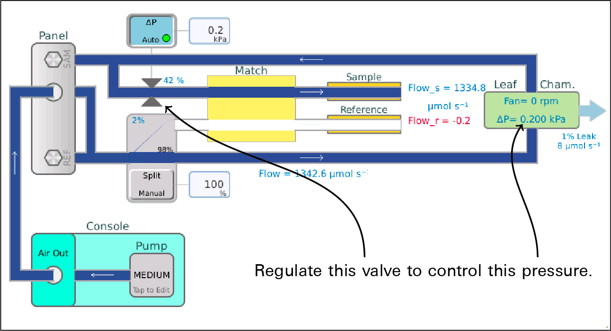
A normal chamber:
Pass Test 1: Can Pchamber be held at 0.2 kPa with pump on high? Measured 0.1 kPa with valve @ 37.0%
Pass Test 2: Can Pchamber be held at 0.2 kPa with pump on medium? Measured 0.1 kPa with valve @ 47.0%
Pass Test 3: Can Pchamber be held at 0.2 kPa with pump on low? Measured 0.1 kPa with valve @ 52.0%
A leaky chamber:
Pass Test 1: Set Pchamber to 0.2 kPa, pump= high? Measured 0.201 kPa, valve= 56.0%
Pass Test 2: Set Pchamber to 0.2 kPa, pump= medium? Measured 0.201 kPa, valve= 59.0%
*** Warning *** Test 3: Set Pchamber to 0.2 kPa, pump= low? Measured 0.164 kPa, valve= 98.0%
Suggestion:
Check the chamber for leaks.
Failed valve (or open chamber):
*** Fail *** Test 1: Set Pchamber to 0.2 kPa, pump= high? Measured 0.007 kPa, valve= 98.0%
Suggestion:
Is the chamber closed?",
*** Fail *** Test 2: Set Pchamber to 0.2 kPa, pump= medium? Measured 0.008 kPa, valve= 98.0%
Suggestion:
Is the chamber closed?",
*** Fail *** Test 3: Set Pchamber to 0.2 kPa, pump= low? Measured 0.009 kPa, valve= 98.0%
Suggestions:
Is the chamber closed?
Is the overpressure sensor zeroed correctly?
Is the pressure valve even working?
Sample cell cal
The LI-6800 does real time chamber leak detection by comparing the main flow meter to the sample cell flow meter. Since the latter is of much lower performance, it usually needs to be calibrated to the main flow meter. (This calibration only comes into play when computing leak corrections - it does NOT change the displayed / logged values of Flow_s.)
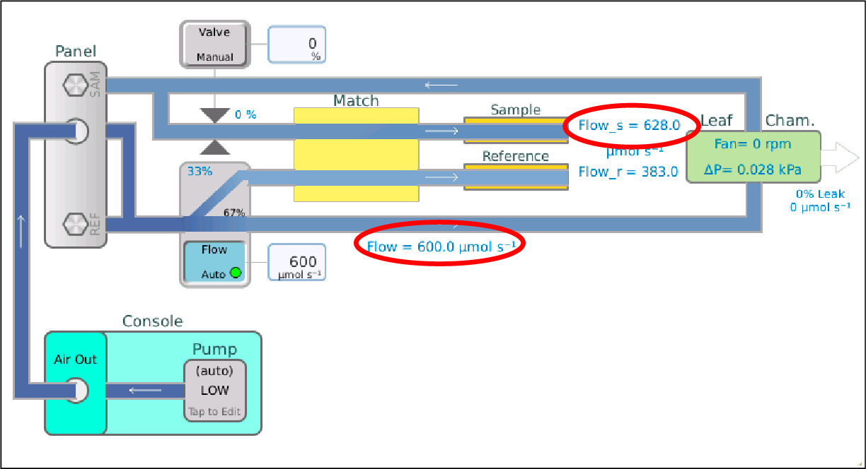
Step 1: Testing for chamber leak: Bypassing chamber
Step 2: Testing for chamber leak: Through chamber
Pass Test 1: Is Flow_s > 400 ? Measured 1081.9
Pass Test 2: Is preliminary leak < 2% ? Measured 1.0
Step 3: Matching at 8 flows
Flow= 0.0, Flow-Flow_s= -1.0
Flow= 102.0, Flow-Flow_s= 14.0
Flow= 407.0, Flow-Flow_s= 9.0
Flow= 600.0, Flow-Flow_s= -28.0
Flow= 801.0, Flow-Flow_s= -65.0
Flow= 1005.0, Flow-Flow_s= -45.0
Flow= 1200.0, Flow-Flow_s= -45.0
Flow= 1401.0, Flow-Flow_s= 19.0
If a preliminary leak test indicates a leak of greater than 2%, an error is triggered, with the suggestion
Is the chamber closed?
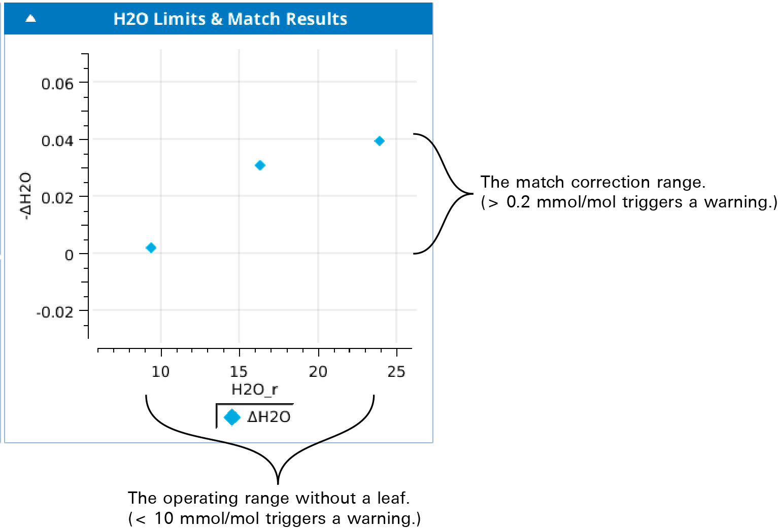
H2O limits & match
This test checks the control range for water, and thus checks the state of the desiccant and humidifier tubes. It also checks how well the IRGAs are matched for water over that range at three points: driest, ambient, wettest.
The final graph is a view of the H2O operating range, and what the match correction looks like over that range. If ambient relative humidity is very low at the beginning of the test, the change may be too small and LI-6800 may report a false failure. You can ignore this, typically.
With working chemicals:
Step 1: Full desiccant
Step 2: Bypass all chemicals
Pass Test 1: Is desiccant effect > 80% of expected? Measured 93% (18.4 mmol/mol)
Pass Test 2: Is lowest H2O_r between -1 and 3? Measured 1.26781
Step 3: Full Humidifier
Pass Test 3: Is Humidifier adding to ambient? (Change = 4.1 mmol/mol)
Pass Test 4: Is the range of ΔH2O < 0.2 ppm? Measured=0.03
Pass Test 5: Is the max |ΔH2O| < 0.1 mmol/mol? Measured=0.03)
With bad desiccant:
Step 1: Full desiccant
Step 2: Bypass all chemicals
*** Warning *** Test 1: Is desiccant effect > 80% of expected? Measured 42% (6.9 mmol/mol)
Suggestion:
Check the desiccant
*** Warning *** Test 2: Is lowest H2O_r between -1 and 3? Measured 9.39568
Suggestions:
Check the desiccant
If the desiccant is good, perhaps the H2O sample and reference are not zeroed properly.
Step 3: Full Humidifier
Pass Test 3: Is Humidifier adding to ambient? (Change = 7.6 mmol/mol)
Pass Test 4: Is the range of ΔH2O < 0.2 ppm? Measured=0.037
Pass Test 5: Is the max |ΔH2O| < 0.1 mmol/mol? Measured=0.039)
With a dry humidifier tube:
Step 1: Full desiccant
Step 2: Bypass all chemicals
Pass Test 1: Is desiccant effect > 80% of expected? Measured 93% (15.6 mmol/mol)
Pass Test 2: Is lowest H2O_r between -1 and 3? Measured 1.10174
Step 3: Full Humidifier
*** Fail *** Test 3: Is Humidifier adding to ambient? (Change = 1.0 mmol/mol)
Suggestion:
Add water to the humidifier tube.
Pass Test 4: Is the range of \ΔH2O < 0.2 ppm? Measured=0.053
Pass Test 5: Is the max |\ΔH2O| < 0.1 mmol/mol? Measured=0.046)
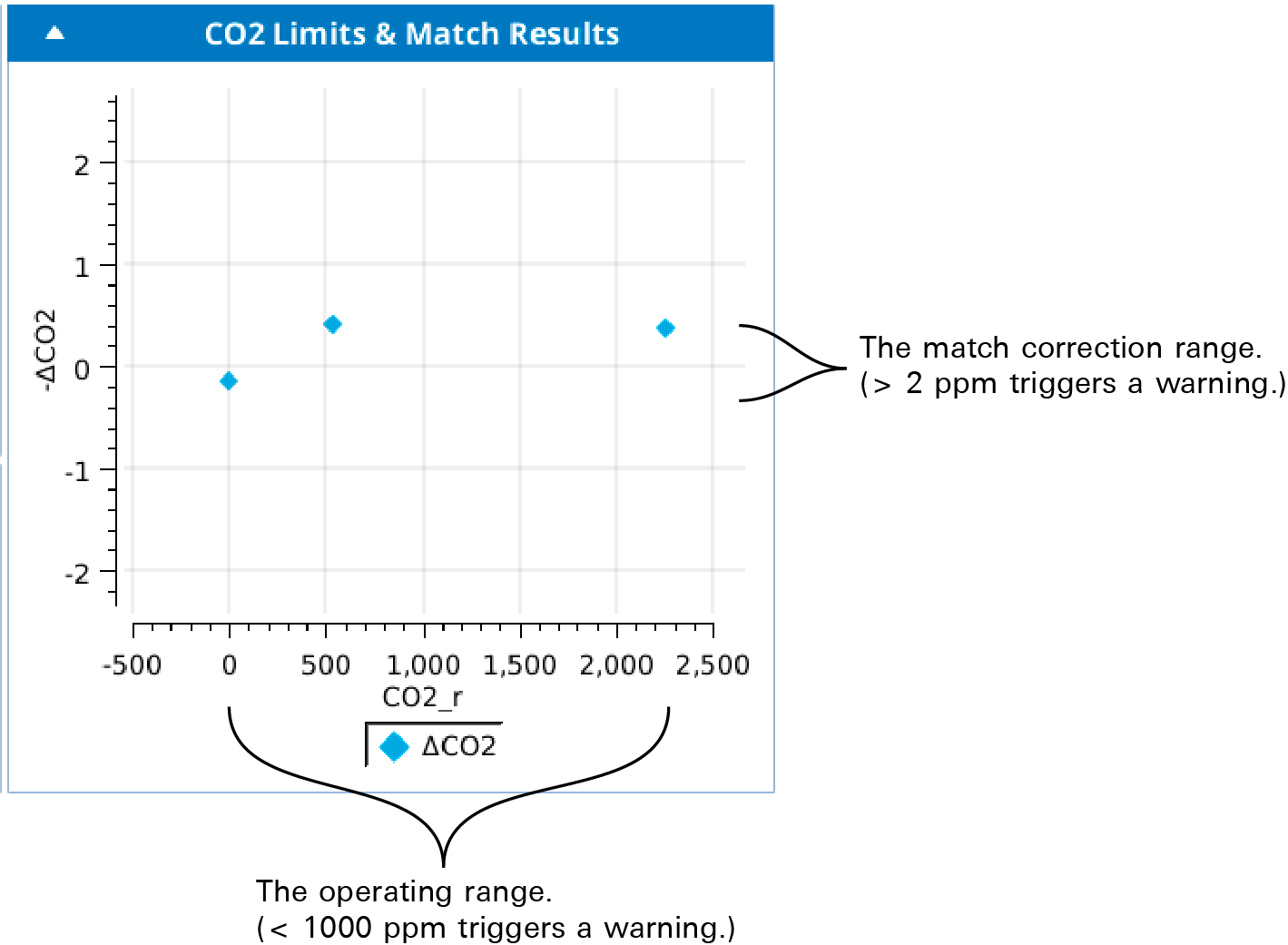
CO2 limits & match
This test checks the control range for CO2, and thus checks the state of the soda lime and CO2 cartridge. It also checks how well the IRGAs are matched for CO2 over that range at three points: scrubbed, ambient, full CO2.
The final graph is a view of the CO2 operating range, and what the match correction looks like over that range.
An open or extremely leaky chamber will produce an error with these suggestions:
*** Fail *** Test 1: Abandoning test because Flow_s < 100. Measured=-0.653923
Suggestions:
Is the chamber closed?
Is the leaf thermocouple installed?",
Test results when everything works as expected:
Step 0: Flushing desiccant and humidifier
Step 1: Ambient
Step 2: Full scrub
Pass Test 1: Is lowest CO2_r between -2 and 5? Measured -0.0357313
Step 3: Full CO2
Pass Test 2: Is highest CO2_r > 1500 ppm? Measured 2251.7
Pass Test 3: Is the range of ΔCO2 < 2 ppm? Measured=0.54
Pass Test 4: Is the max |ΔCO2| < 1 ppm? Measured=0.4
Test 1 catches zeroing issues...
*** Warning *** Test 1: Is lowest CO2_r between -2 and 5? Measured -2.53
Suggestion:
Check the CO2 zero for reference and sample.
... and soda lime issues:
*** Warning *** Test 1: Is lowest CO2_r between -2 and 5? Measured 9.8
Suggestion:
Check the soda lime.
If the soda lime is good, perhaps the CO2 sample and reference are not zeroed properly.
Test 2 catches empty CO2 cylinders:
*** Warning *** Test 2: Is highest CO2_r > 1500 ppm? Measured -0.1
Suggestion:
Replace the CO2 cylinder.
If Test 3 fails, and the offset looks like a zeroing issue:
*** Warning *** Test 3: Is the range of ΔCO2 < 2 ppm? Measured=8.7
Suggestions:
Check the zero: CO2_r and CO2_s are not well matched at low CO2.
Consider implementing CO2 range matching.
If Test 3 fails, and the offset looks like a spanning issue:
*** Warning *** Test 3: Is the range of ΔCO2 < 2 ppm? Measured=8.7
Suggestions:
Check the spans: CO2_r and CO2_s are not well matched at high CO2.
Consider implementing CO2 range matching.
If Test 3 passes, there will be a Test 4 to catch an obvious match need:
*** Warning *** Test 4: Is the max |ΔCO2| < 1 ppm? Measured=2.4
Suggestions:
Matching will take care of this.
Chamber leak
The chamber leak test is a two-part leak test, comparing the Flow_s readings with all air going though the chamber, with all air going directly to the sample cell bypassing the chamber. This is potentially more accurate than the live leak indicator, since the former uses the same flow meter, while the latter uses separate flow meters and depends on their inter calibration.
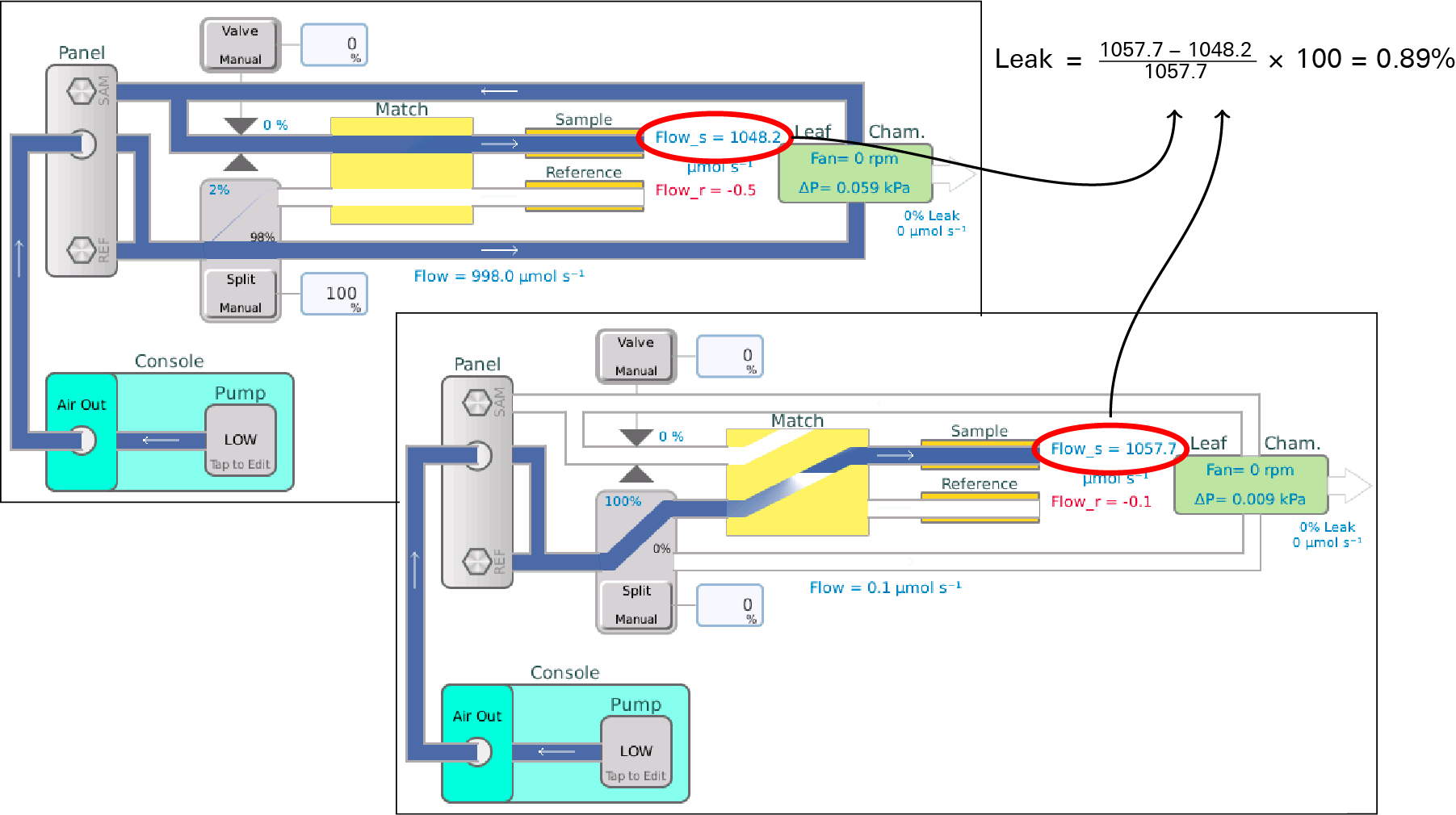
Leaks less than 1% are pass the test; between 1 and 2% will generate a warning, and above 2% is an error,
Step 1: All flow bypasses the leaf chamber
Bypass flow = 1057.7
Step 2: All flow passes through the leaf chamber
Chamber flow = 1048.2
Pass Test 1: Leak rate < 1% ? Measured=0.9
Leaks below 50% merit these suggestions:
*** Fail *** Test 1: Leak rate < 1% ? Measured=22.6
Suggestions:
Check the gaskets.
Improve sealing around any stems.
Above 50% produces these suggestions:
*** Fail *** Test 1: Leak rate < 1% ? Measured=99.3
Suggestions:
Is the chamber closed?
Is the leaf temperature thermocouple installed?
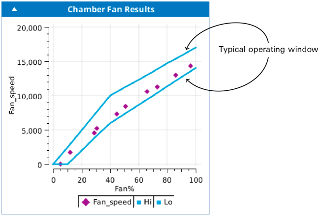
Chamber fan
The chamber fan test sets the fan to a series of 10 setpoints, each randomly chosen in a fixed interval. For each setpoint, there is a typical expected range of resulting fan speeds. If your results have a point or two just outside the expected range, you can safely ignore it. If all or most points are well out (such as all at 0), then there is clearly a problem. If there seems to be a problem with the fan not coming on at lower power settings (or at any setting), then power the head off, remove the chamber, and look for debris obstructing the fan.
Pass Test 1: 5.2% produces 5 rpm. Is that between 0.0 and 1300.0 rpm?,
Pass Test 2: 12% produces 1680 rpm. Is that between 400.0 and 3000.0 rpm?,
Pass Test 3: 28.6% produces 4560 rpm. Is that between 3720.0 and 7150.0 rpm?,
Pass Test 4: 30.7% produces 5210 rpm. Is that between 4140.0 and 7675.0 rpm?,
Pass Test 5: 44.6% produces 7295 rpm. Is that between 6613.0 and 10537.0 rpm?,
Pass Test 6: 50.7% produces 8410 rpm. Is that between 7427.0 and 11248.0 rpm?,
Pass Test 7: 65.9% produces 10585 rpm. Is that between 9453.0 and 13022.0 rpm?,
Pass Test 8: 73.1% produces 11285 rpm. Is that between 10413.0 and 13862.0 rpm?,
Pass Test 9: 85.8% produces 12960 rpm. Is that between 12107.0 and 15343.0 rpm?,
Pass Test 10: 96.5% produces 14335 rpm. Is that between 13533.0 and 16592.0 rpm?,
If the fan does not appear to be running at any power above 30%, an error with this suggestion is produced:
Power off, remove chamber, check for debris blocking the fan.
Any other violation is a warning with this suggestion:
Fan speeds slightly out of the envelope can be ignored.
Heat exchanger
The heat exchanger test does a three setpoint test using the heat exchanger, to make sure it is working. If there are failures, contact LI-COR.
Doing 3 random Txchg setpoints,
Pass Test 1: Is Txchg within 0.2 of 33.3%? Measured 33.22 after 71.0 s,
Pass Test 2: Is Txchg within 0.2 of 23.3%? Measured 23.332 after 75.5 s,
Pass Test 3: Is Txchg within 0.2 of 28.3%? Measured 28.212 after 50.5 s,
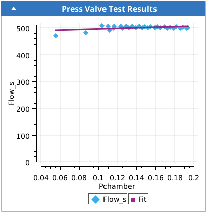
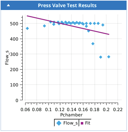
Press valve test
This tests attempts to detect harmonic vibrations set up in the pressure control valve that might influence the Flow_s flow sensor. The pressure control is ramped up to 0.2 kPa and back, while the Flow_s sensor is monitored. Normally there is little or no effect on Flow_s, but a vibrating valve can cause a sudden apparent drop in the Flow_s reading.
A normal valve looks like this:
Pass Test 1: Is Slope of Flow_s with Pchamber > -500?: Measured=103.0
A vibrating valve looks like this:
*** Warning *** Test 1: Is Slope of Flow_s with Pchamber > -500? : Measured=-850.0
Suggestions:
The pressure valve seems to be resonating and interfering with the Flow_s sensor.
You can avoid this by operating at low (or no) overpressure, or by putting a very slight flow restriction on the exhaust A port of the IRGA head.
This is fixable, but requires servicing by LI-COR.
An open or extremely leaky chamber will produce an error with these suggestions:
*** Fail *** Test 1: Abandoning test because Flow_s < 100. Measured=-0.653923
Suggestions:
Is the chamber closed?
Is the leaf thermocouple installed?,
Soil chamber test
The soil chamber test is only available when the soil chamber is attached. The test checks for chamber opening and closing, and circulation between the chamber and head.
Testing Open/Close
Pass Test 1: Chamber closing time expected to be 12 s +/- 6? Measured 12.0
Pass Test 2: Chamber opening time expected to be 12 s +/- 6? Measured 9.0
Testing Circulation Pump
Pass Test 3: Max circulation flow > 1000? Measured 1367.26
Pass Test 4: Flow leakage (Flow_r+Flow) < 5 ? Measured 0.724502
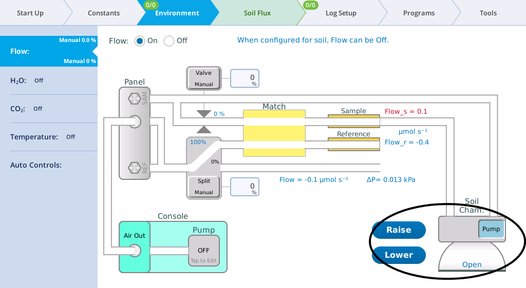
These actions can also be tested manually from the Environment > Flow page.
Problems here are usually due to improper plumbing, kinked tubing, etc., and produce these suggestions:
Incorrect soil chamber plumbing?
Flow from IRGA obstructed?