Overview of the instrument
The LI-7200RS is a high performance closed-path CO2/H2O gas analyzer designed for use in eddy covariance flux systems. It is also suitable for profile measurements, relaxed eddy accumulation measurements, gradient flux techniques, pCO2 measurement systems, or any other application that depends on high-speed, high-precision CO2 gas or water vapor measurements.
The LI-7200RS computes dry mole fractions of CO2 or H2O in the air sample using measurements of the sample temperature and pressure. These variables account for changes in air density due to the water vapor content, pressure, and temperature of the sample air. CO2 dry and H2O dry are computed as mole of gas per mole of dry air, and can be used for computing eddy covariance fluxes without the need for density corrections (Webb et al., 1980).
Here we describe how to use the LI-7200RS, SmartFlux 2 System, and the 7200-102 flow module in eddy covariance systems. However, you can use the LI-7200RS as a general purpose gas analyzer without either of these two components, using features described in Software reference. You can also use it with the original 7200-101 flow module and the original SmartFlux System, which are described elsewhere.
What’s what
If you have just taken delivery of your instrument, check the packing list to verify that you have received everything that was ordered.
LI-7200RS sensor head
The sensor head is the gas analyzer. It includes air temperature thermocouples, a differential pressure sensor, and some electronics.
Important: There are fine-wire thermocouples that measure air temperature at the air inlet and outlet ports. Do not insert long objects (e.g., narrow tubing or screwdriver) into the inlet or outlet ports. Doing so will damage the thermocouples.
LI-7200RS sensor head spares kit
Part Number: 7200-028
The LI-7200RS sensor head parts kit includes accessories and replacement parts for the sensor head.
Head cable assembly
Part Number: 9972-012
Connects the sensor head to the LI-7550 Analyzer Interface Unit. The assembly has a cable for the IRGA, a cable for thermocouples, and a tube for the pressure sensor.
Gas analyzer accessories
The following accessories are available for the instrument. Some components are included with the instrument; others are sold separately as indicated.
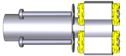
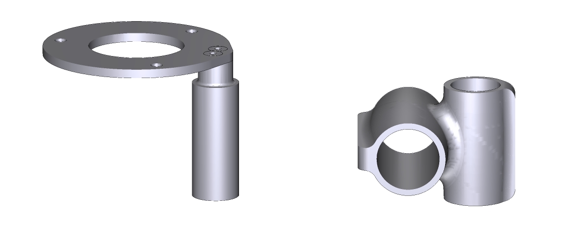
Head mounting post
Part Number: 9972-046
Included in the instrument spares kit, the mounting post is to mount the LI-7200RS head in a ¾" swivel mount. It has yellow dampers that protect the instrument from vibrations.
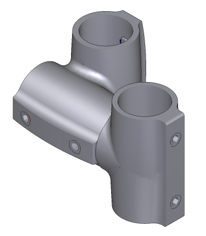
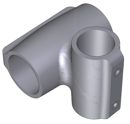
Head mounting kit
Part Number: 7900-340
Available as an option. The head mounting kit is used to install the gas analyzer head on a cross arm.
| Description | Quantity | Part Number |
|---|---|---|
| Swivel Mount (¾") | 1 | 7900-344 |
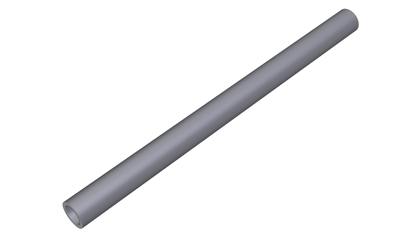
| 56 cm Riser Bar (¾" IPS) | 1 | 9879-046 |
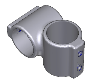
| Crossover Fitting (¾" × 1") | 1 | 7900-342 |

Intake tube mounting options
Available as optional components. To provide additional support for the insulated or heated intake tube, use one 56 cm riser bar (¾" diameter; 9879-046) and two ¾" × 1" crossover fittings (7900-342).
Heated intake tube
Part Number: 7200-050
The optional heated intake tube improves water vapor frequency response by reducing relative humidity in the intake tube. The heated intake tube is recommended where the relative humidity is above 50%. Older instruments should use part number 7200-040. Contact your sales representative for details.
| Description | Part Number |
|---|---|
| Swagelok Spacer with Nuts and Ferrules | - |
| Accessory T-splitter (old version) | 392-10502 |
| Accessory Cable Splitter (new version) | 392-17153 |
| Power Supply Splitter Cable | 392-15382 |
| Power & Communication Adapter Cable | 392-15383 |
Head cable extension
Part Number: 9972-032
An optional 5-meter extension can be connected to extend the distance between the sensor head and the LI-7550 Analyzer Interface Unit to 10 meters. Only one extension cable can be used.
Data cables
Optional data cables with 8-pin Eurofast-to-RJ45 connectors are available in 5-, 25-, and 50-meter lengths. These cables connect the external Ethernet terminal on the LI-7550, LI-7500DS, or LI-7700 to a network switch.
| Description | Part Number |
|---|---|
| 5 meter data cable (optional) | 392-13977 |
| 25 meter data cable (optional) | 392-16699 |
| 50 meter data cable (optional) | 392-13767 |
Calibration certificate
The certificate lists the calibration coefficients for your sensor head. These values are unique to each sensor head and have been entered into the corresponding LI-7550 at the factory. Keep this sheet in case you need to re-enter these values. You can acquire a copy of your calibration certificate from the LI-COR support web site.
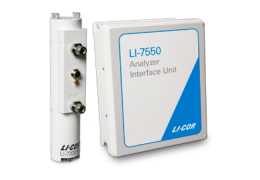
LI-7550 Analyzer Interface Unit
The LI-7550 Analyzer Interface Unit houses the gas analyzer electronics. There is a USB port and three Ethernet connectors inside the LI-7550. Two of the Ethernet ports are connected to the connector panel.
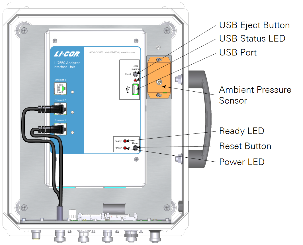
- USB Eject Button: Press to eject the USB drive. Failure to press the eject button before removing the USB flash drive may result in the loss of data and may require a restart to resume normal operation.
- USB Status LED: Indicates the status for the flash drive:
-
- Solid: Drive mounted, not logging.
- Rapid Blink: Logging data.
- Slow Blink: Error. Eject and reinsert the drive.
- Off: Drive not mounted; OK to remove.
- USB Port: A USB drive must be installed in order to log data. Two compatible drives are in the spares kit.
- Ready LED: On when the instrument is warmed up and ready to measure.
- Reset Button: Press to restart the LI-7550 and gas analyzer.
- Power LED: On when the instrument is powered on.
The connector panel has connectors for the sensor head and other cables.
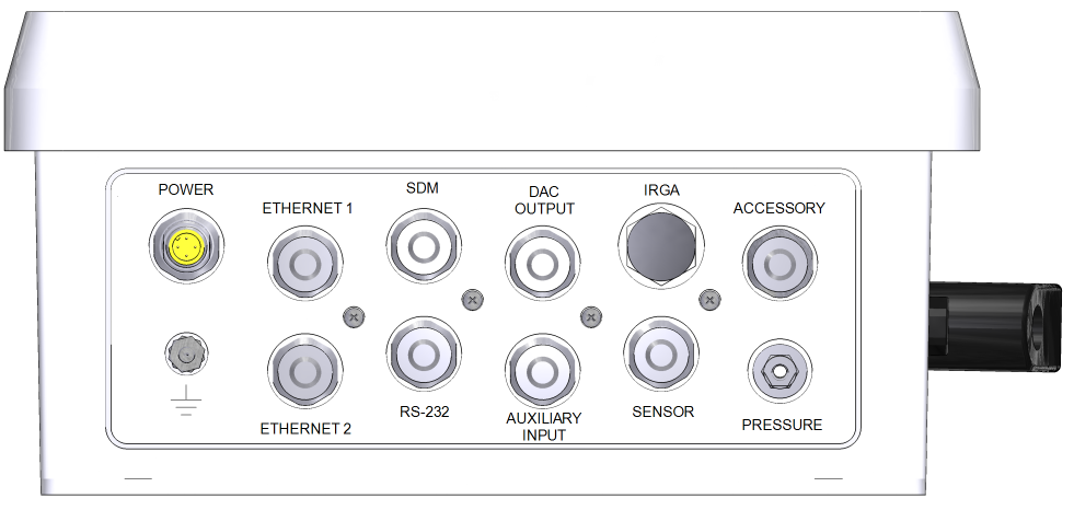
- POWER: For the power cable (9975-030). Apply 10.5 to 30 VDC, 30 W minimum to power on the instrument.
- ETHERNET 1 and 2: Sealed connectors for network cables. Typically connected to cable part numbers 392-10107 and 392-10108 to connect with other networked devices through the Brainboxes SW-508 network switch.
- SDM: Connector for an SDM outputs using cable 392-10093.
- DAC OUTPUT: Connector for analog outputs. Connects to cable 392-10109 or the 7550-101 Auxiliary Sensor Interface.
- IRGA: Connector for the data cable from the gas analyzer.
- ACCESSORY: Connector for accessories, including the flow module and heated intake tube. A splitter cable is required to use both.
- GROUND lug: Connects the gas analyzer to an earth ground.
- RS-232: Connector for serial data using cable 392-10268.
- AUXILIARY INPUT: Connector for inputs. Connects to cable 392-10109 or the 7550-101 Auxiliary Sensor Interface.
- SENSOR: Connector for LI-7200RS head thermocouple cable.
- PRESSURE: Connector for the LI-7200RS head pressure tube.
LI-7550 spare parts kit
Part Number 9975-023
The LI-7550 Analyzer Interface Unit has a spare parts kit. It includes the cables and mounting bracket. As you become familiar with the analyzer you will learn which items to keep close at hand and which items can be stored away.
| Description | Quantity | Part Number |
|---|---|---|
| Power Cable (5 m) | 1 | 9975-030 |
| 16 GB USB Flash Drive | 2 | 616-10723 |
| Mounting Kit | 1 | 9979-022 |
| RS-232 Serial Cable (5 m) | 1 | 392-10268 |
| Analog Input/Output Cable (5 m) | 1 | 392-10109 |
| Ethernet Cable (8-pin Turck® Connectors; 5 m) | 1 | 392-10108 |
| Ethernet Adapter Cable, 8-pin Turck to RJ45 | 1 | 392-10107 |
| Standard Ethernet Cable (2.1 m) | 1 | 616-06116 |
| SDM Cable (5 m) | 1 | 392-10093 |
| 5 Amp Fuse | 2 | 439-04214 |
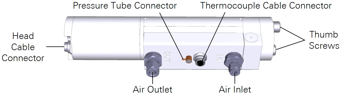
Flow module
Part Number: 7200-101 or 7200-102
The flow module provides controlled air flow through the gas analyzer. Although optional, the flow module is recommended because it provides flow data that is recorded in the gas analyzer dataset.
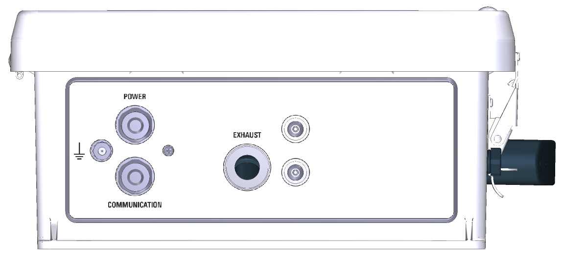
The connector panel features an air outlet (EXHAUST), power cable connector, communications cable connector, and a ground lug. Early models (7200-101) have the intake on the bottom of the enclosure. Later models (7200-102) have the intake on top of the enclosure. Otherwise, the flow modules are the same.
Inside the case, you'll find a panel with indicator LEDs and controls. Although you can alter the flow settings and read diagnostics through the control panel, we recommend controlling flow through the software. See Flow module interior control panel for details on the LEDs and controls.
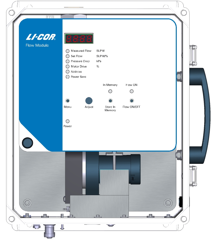
Note: When you start up the system for the first time, record the Pressure Drop and Motor Drive (%) readings to establish a baseline of normal, unobstructed readings.
Flow module spare parts kit
Part Number: 9972-087
This kit contains replacement parts for your 7200-102. Among other items, the spares kit contains tubing and the power and accessory cables. As you become familiar with the flow module you will learn which items to keep close at hand and which items can be stored away. The spares kit includes these commonly used items:
| Description | Quantity | Part Number |
|---|---|---|
| Power Cable (5 m) | 1 | 9975-030 |
| Data Cable (5 m) | 1 | 392-10092 |
| Tygon Tubing, ¾” O.D. (5 m) | 1 | 222-10384 |
| Hose Barb (3/8” NPT) for Flow Module Inlet | 1 | 300-11179 |
| Hose Barb (¼” NPT) for Head Outlet | 1 | 300-11180 |
| Hose Clamps (½”) | 6 | 300-10788 |
| Cylindrical Exhaust Screen; disposable (w/ 7200-102) | 2 | 301-18828 |
| Mounting Kit | 1 | 9979-022 |
| Hose Barb (3/8” NPT) for Flow Module Outlet | 1 | 300-11179 |
| Muffler and Filter Assembly | 1 | 301-10381 |
| Spare Mesh Filter | 1 | 301-10382 |
The SmartFlux® 2 System
Part Number: 7900-600
The SmartFlux 2 System houses the datalogging and processing computer. It provides GPS position and time synchronization, connections for digital sonic anemometer data, a USB port for logging data to a USB storage device, and a microcomputer that runs EddyPro Software.
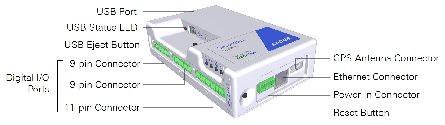
- USB Port: Hosts a USB drive for data logging.
- USB Status LED: Indicates data transfer status.
- Solid: Normal operation.
- Rapid Blink: Logging or reading data.
- Slow Blink: Error. Eject and reinsert the drive.
- USB Eject Button: Press to eject the drive. Failure to press the eject button before removing the USB flash drive may result in the loss of data.
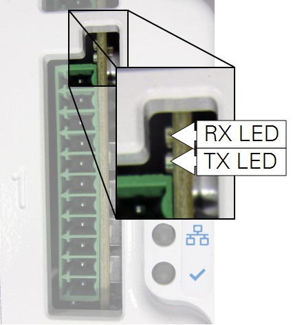
- Digital I/O Terminals: These three ports can read digital data from a sonic anemometer and a LI-COR Data Acquisition System. Each digital I/O port has two LEDs that are visible at the top of each connector:
-
- RX LED (receiving) and TX LED (transmitting):
- Rapid Blink or On: Receiving or transmitting data.
- Off: Normal operation; waiting.
- RX LED (receiving) and TX LED (transmitting):
- GPS Antenna Connector: Accepts the GPS antenna cable. When connected, time and location data can be set by GPS satellites.
- Ethernet Connector: Standard RJ45 jack for an Ethernet cable. Connects to a port on the Brainboxes SW-508.
- Power In Connector: Requires a 10 to 30 VDC power supply capable of providing 3.5 W.
- Reset Button: Press to reboot the SmartFlux System.
- Indicator LEDs: In addition to the digital I/O port LEDs and USB status LEDs, the SmartFlux System has four status LEDs:
- Power IN (
 ):
): - Solid: System is powered.
- Off: System not powered.
- Power OUT ():
- Solid: Power delivered to digital I/O ports 1, 2, or 3, on pins 1 and 2.
- Off: Power not delivered. If Power IN is on, but Power OUT is off, then a fuse inside the SmartFlux System has failed.
- Ethernet Activity (
 ):
):- Rapid Blink or On: Network communication.
- Off: No network communication
- Status (
 ):
): - Slow Blink: System is ready.
- Solid: Starting up.
- Power IN (
The SmartFlux 2 System includes the following components:
Important: A USB flash drive must be installed in the LI-7550 USB port when recording data. A USB flash drive can be installed in the SmartFlux 2 System to provide a full duplicate of data from the LI-7550 USB drive. It also holds optional PhenoCam images and ICOS files. In a tower installations, where the LI-7550 is mounted high off of the ground, the SmartFlux 2 System can be installed closer to the ground, making the USB drive accessible.
Brainboxes SW-508 network switch
Part Number: 616-16771
8-port unmanaged network switch with power wires. Expands the number of Ethernet connections available. Complete documentation for the switch is available from brainboxes.com.
Caution: Do not use network switches other than the Brainboxes SW-508. Other network switches may provide undependable network performance that could result in data loss.
Software
Several software applications are available for the LI-7200RS, including the Windows application software, embedded instrument firmware, EddyPro Software, and other applications. Go to licor.com/support/LI-7200RS/software.html for the latest versions. Update the instrument firmware before deploying it.
Windows interface application software
The Windows interface software is used to configure the gas analyzer and SmartFlux System and set parameters for the eddy covariance system. It is compatible with Windows computers running Windows 7 and newer operating systems.
EddyPro® Software
EddyPro Software for the desktop (macOS or Windows) is not required to use the instrument because EddyPro is installed on the SmartFlux System. The EddyPro desktop application is required if you want to run an advanced configuration on the SmartFlux System or if you want to reprocess eddy covariance raw data.
File viewer software
The File Viewer is a simple application for viewing raw data from LI-COR sensors. It reads compressed data files and displays plots of the data.
FluxSuite® Software
FluxSuite is a web-based application that enables you to monitor LI-COR eddy covariance systems that are connected to the internet through a direct Ethernet connection, cellular gateway, or satellite internet terminal. FluxSuite provides site status information, summary results, and configurable email alerts regarding site status. See licor.com/products/eddy-covariance/fluxsuite for details.
Tovi® Software
Tovi is a suite of tools for analyzing eddy covariance flux and meteorological datasets that have been processed with EddyPro Software. Tovi is designed to bring together analysis tools, developed by or with the scientific community, into a unique, interactive and intuitive environment, to facilitate and streamline typical processes such as quality control, flux gap filling and flux partitioning, as well as to enable novel analysis such as footprint-based flux allocation. Go to https://shop.licor.com/shop/software/tovi/register/ for more information.
Enclosures and accessories
Electronics enclosures are available as optional accessories for the system.
Pre-configured biomet system enclosure
Part Number: 7900-126
The pre-configured enclosure is a large weather resistant box with mounting hardware. It is set up for the LI-COR Biomet Data Acquisition System and other accessories. It includes all of the terminal connections and DIN rails required for a complete eddy covariance system.
Eddy covariance system enclosure
Part Number: 7900-050
A basic enclosure with a minimal set of internal components. Includes a pre-drilled internal back plate, three DIN rails for mounting components, and three strain relief fittings. It is best to pair this with the Power Distribution Kit (7900-235).
Power distribution kit
Part Number: 7900-235
Includes DIN-mountable terminal connections, shorting blocks, and a 10-amp circuit breaker. Provides 11 individual positive and negative power terminals for the system. Installs in the 7900-050 eddy covariance system enclosure.
| Description | Quantity | Part Number |
|---|---|---|
| 10-amp Circuit Breaker; DIN Mountable | 1 | 275-13499 |
| DIN Terminal Cover | 1 | 331-12825 |
| DIN Terminal End Bracket | 2 | 331-12922 |
| Red 4 mm Terminals; DIN Mountable | 6 | 331-13508 |
| Green 4 mm Terminals; DIN Mountable | 1 | 331-13510 |
| Black 4 mm Terminals; DIN Mountable | 6 | 331-13511 |
| 6-position Shorting Box | 2 | 331-13512 |
| 14 AWG Red Wire Lead | 1 | 392-13829 |
| 18 AWG Green/Yellow Ground Wire Lead | 1 | 372-04621 |
Auxiliary Sensor Interface
Part Number: 7550-101
An O-ring sealed, weatherproof junction box that can be used to connect analog inputs or outputs to the LI-7550 Analyzer Interface Unit. It has connections for up to six analog outputs or four general purpose analog inputs and a constant 5 VDC source (5 mA maximum). The 7550-101 includes mounting hardware, Santoprene™ tubing and plugs for unused openings.
| Description | Quantity | Part Number |
|---|---|---|
| U-Bolt, ¼ x 20 | 2 | 184-09842 |
| Hex Nut | 4 | 163-00138 |
| Santoprene (1/16” inside diameter; 0.6 m) | 1 | 222-08325 |
| Quick Connect Plug | 10 | 300-07393 |
Sonic anemometer cables and mounting hardware
Optional data and power cables are available for all supported anemometer models. Mounting hardware is available for several models.
Gill WindMaster/Pro and R3
Data and power cables
Part Number: 7900-415-x
The data/power cable is available in three lengths. The USB-to-RS-422 cable is used to connect the anemometer to a computer.
Mounting hardware
Part Number: 7900-342
To mount the WindMaster/Pro and R3, use a ¾" × 1" cross-over fitting (7900-342) and anemometer mounting post (900-11242). The mounting post is included with WindMaster/Pro anemometers purchased from LI-COR. The cross-over fitting is available seperately.
| Description | Quantity | Part Number |
|---|---|---|
| WindMaster/Pro Mounting Post | 1 | 900-11242 |
| Crossover Fitting (¾" × 1") | 1 | 7900-342 |
Gill HS-50 and R3-50
Data and power cables
Part Number: 7900-445-x
The data/power cable is available in three lengths. The USB-to-RS-422 cable is used to connect the anemometer to a computer.
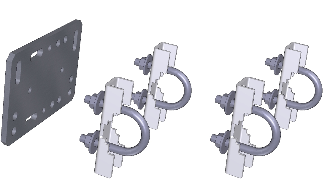
HS-50 Mounting hardware
The HS-50 can be mounted with the following components. The R3-50 mounting options are similar to the WindMaster/Pro. Mounting is accomplished with two hardware packs. Use the two 35 mm U-bolts from each cross arm hardware pack. The larger 64 cm U-bolts are not used.
| Description | Quantity | Part Number |
|---|---|---|
| Crossover Fitting (1" × 1") | 1 | 259-17893 |
| 45 cm Riser Bar (1" IPS) | 1 | 9879-095 |
| Cross-arm Plate | 1 | 9879-020 |
| Cross-arm Brackets | 4 | 9879-043 |
| Cross-arm Hardware Pack | 2 | 9979-018 |
Campbell Scientific CSAT3
Part Numbers: 7900-454-x and 7900-452-x
Data and power cables are available in two lengths. The USB-to-RS-232 cable is used to connect the anemometer to a computer.
Campbell Scientific CSAT3B
Part Numbers: 7900-464-x and 7900-462-x
Data and power cables are available in two lengths.
Metek MultiPath Class A
Data and power cables
Part Number: 7900-492-x
The data/power cable is available in three lengths. The USB-to-RS-232/RS-485 cable is used to connect the anemometer to a computer.
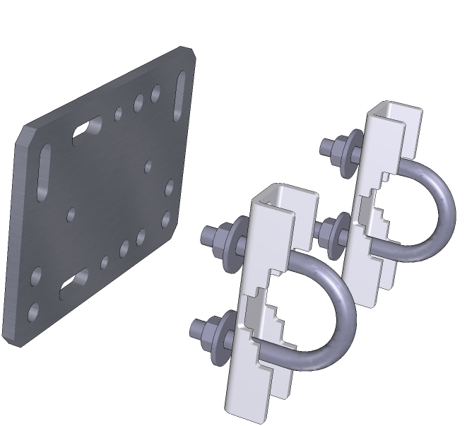
Mounting kit
Part Number: 7900-336
Mount the Metek Class A anemometer with the Metek mounting kit (7900-336).
| Description | Quantity | Part Number |
|---|---|---|
| Crossover Fitting (1" × 1") | 1 | 259-17893 |
| 45 cm Riser Bar (1" IPS) | 1 | 9879-095 |
| Cross-arm Plate | 1 | 9879-020 |
| Cross-arm Brackets | 2 | 9879-043 |
| Cross-arm Hardware Pack | 1 | 9979-018 |
Metek MultiPath Cage
Data and power cables
Part Numbers: 7900-482-x
The data/power cable is available in three lengths. The USB-to-RS-232/RS-485 cable is used to connect the anemometer to a computer.
Mounting kit
Part Number: 7900-346
Mount the Metek Cage anemometer with one 1" × 1" crossover fitting (7900-346).
RM Young 81000x
Data and power cables
Part Number: 7900-472-x
The data/power cable is available in three lengths. The USB-to-RS-232/RS-485 cable is used to connect the anemometer to a computer.
Mounting kit
Part Number: 7900-332
Mount the RM Young 81000, 81000V, 81000RE, or 81000VRE sonic anemometer with the RM Young mounting kit (7900-332).
| Description | Quantity | Part Number |
|---|---|---|
| Crossover Fitting (1" × 1") | 1 | 7900-346 |
| 45 cm Riser Bar (1" IPS) | 1 | 9879-095 |