Initial assembly
The following section covers the basic steps you will follow to assemble the LI-7200RS for the first time. You'll need the analyzer head, LI-7550, flow module, SmartFlux 2 System, and the accessories.
Preparing the gas analyzer
Begin by installing tubing and data cables that connect the head, flow module, and LI-7550. Also install the LI-7550 USB drive.
Installing the flow module tubing
The 5 m (16.4’) length of Tygon tubing is used for air flow between the LI-7200RS head and the flow module. To attach tubing:
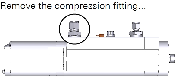
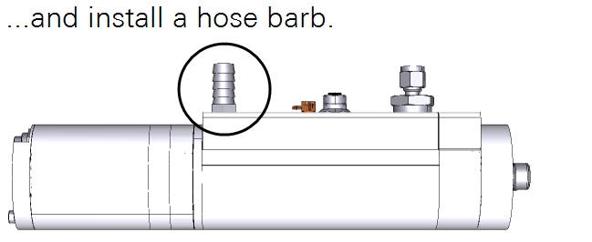
- Install the hose barb on the head outlet.
- On the LI-7200RS head, remove the compression fitting on the AIR OUT port and install the ¼” hose barb (part number 300-11180 from the flow module spares kit). Tighten the hose barb with an open end wrench.
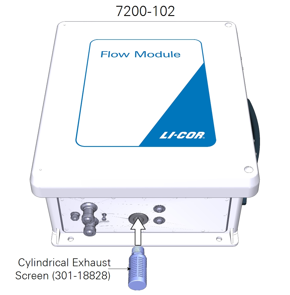
- Remove the red plugs from the EXHAUST port on the connector panel and the port on the top of the case of the flow module.
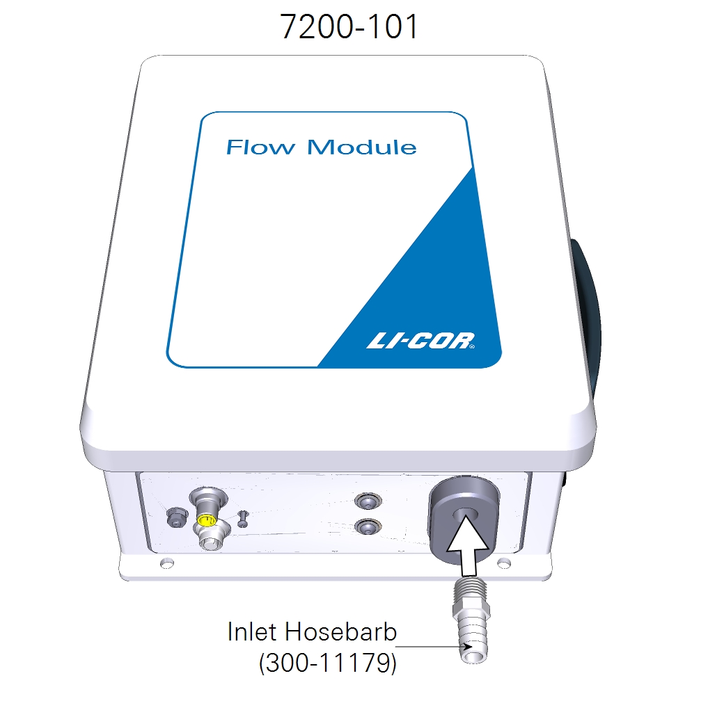
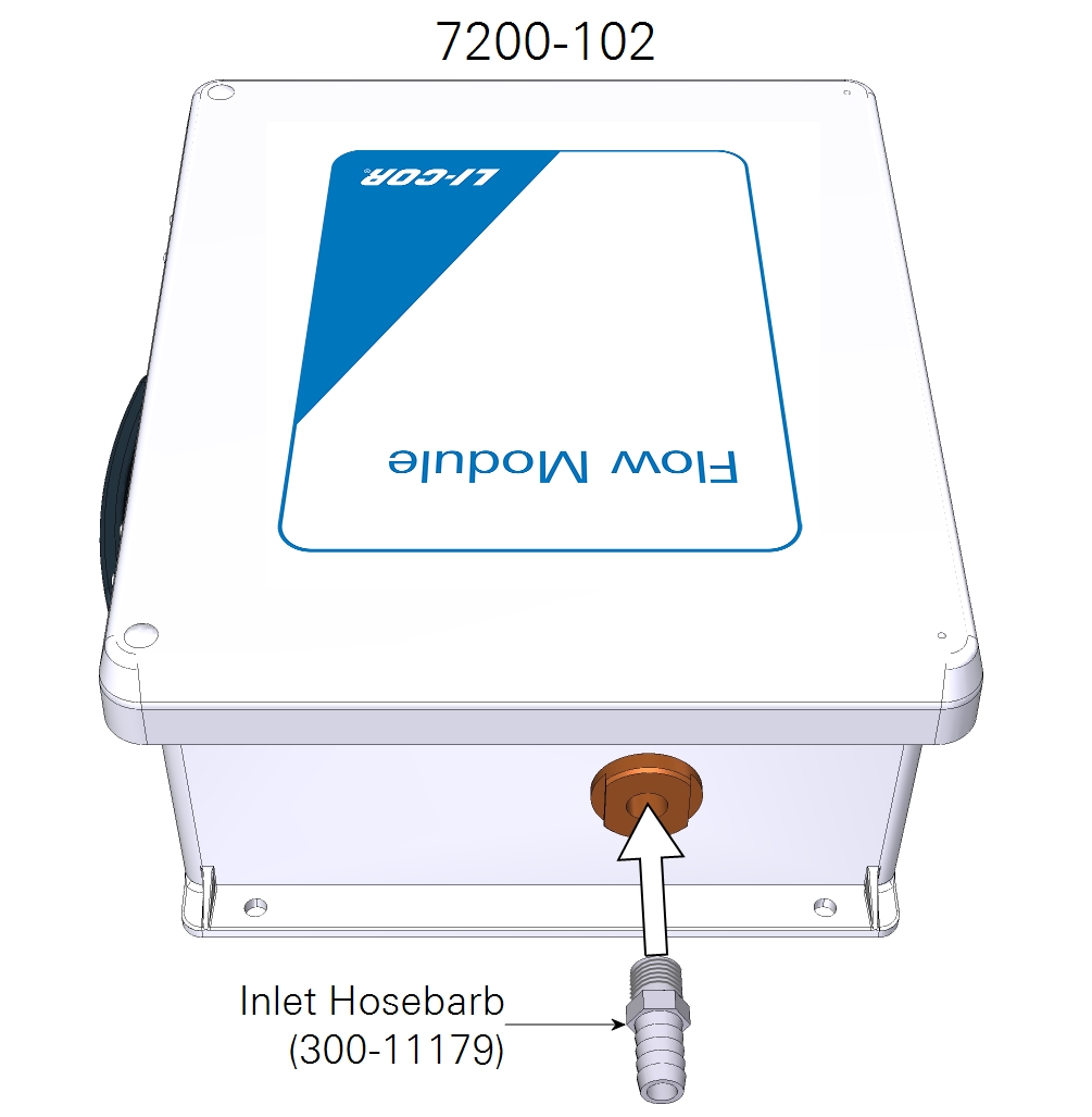
- Install the inlet hose barb fitting (part number 300-11179) in the port on the top of the case.
- Tighten the fitting securely with an open end wrench.
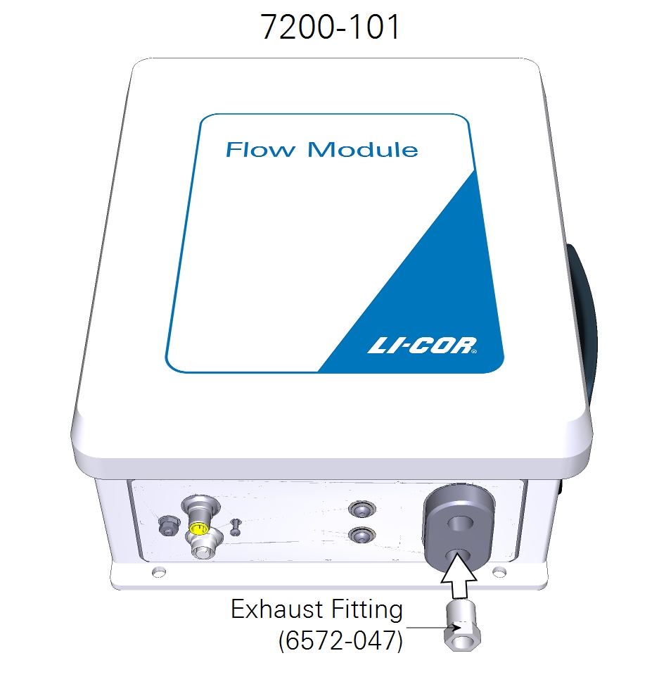
- Install the exhaust fitting (6572-047 for the 7200-101) or cylindrical exhaust screen (301-18828 for the 7200-102) in the exhaust port.
- The screen keeps bugs out of the flow module outlet. Tighten the fitting securely on the exhaust outlet. If using a muffler instead, see Adding a muffler to the air outlet.
- Install the inlet hosebarb on the flow module.
- The hose barb fits into the bottom of the 7200-101 or top of 7200-102.
- Install the black Tygon tubing between the LI-7200RS head air outlet and the flow module air inlet.
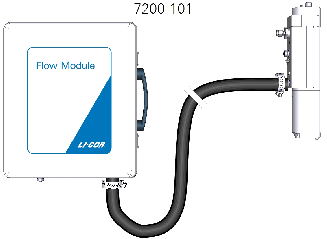
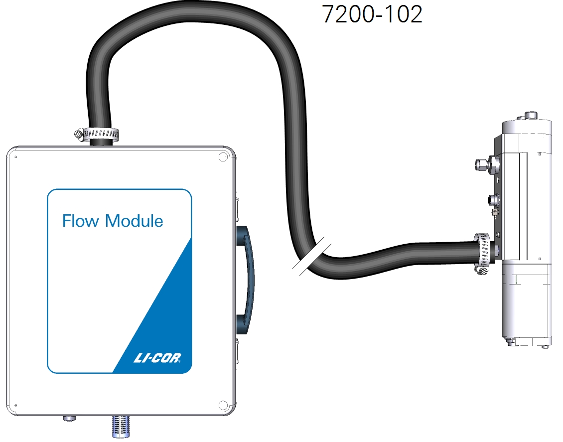
- Connect the tubing at the hose barb on the LI-7200RS sensor head with a hose clamp from the spares kit. Connect the other end to the flow module inlet.
- After you install the analyzer and flow module at the site, trim the tube to a suitable length. The appropriate length for the tube will depend on your site configuration - the distance between the analyzer head and the flow module.
Important: Always use hose clamps to secure the Tygon tubing to the hose barbs. The tubing will initially seal without hose clamps, but leaks will develop slowly over time if the tube is not secured with hose clamps.
Attaching the intake tube
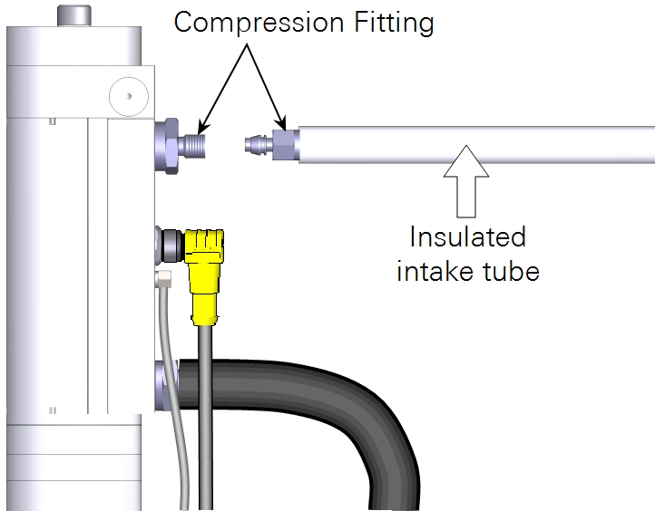
The LI-72000RS includes an insulated 1-meter intake tube (part number 9972-053). The insulated intake tube can be shortened, which, can reduce temperature attenuation, but make it difficult to mount the analyzer without distorting the wind flow. A longer intake tube can lead to higher water vapor signal attenuation and require more power from the pump. The ideal length is between 0.5 and 1 meter, but you can make it as short as 15 cm.
Leave the insulation intact to prevent condensation from forming inside the tube. A reflective film can be placed on top of the insulation to minimize solar heating of the intake surface near the sonic anemometer.
An optional heated intake tube (part number 7200-050) is recommended in extremely cold or humid (>50% RH) environments. The heated intake tube cannot be shortened or bent.
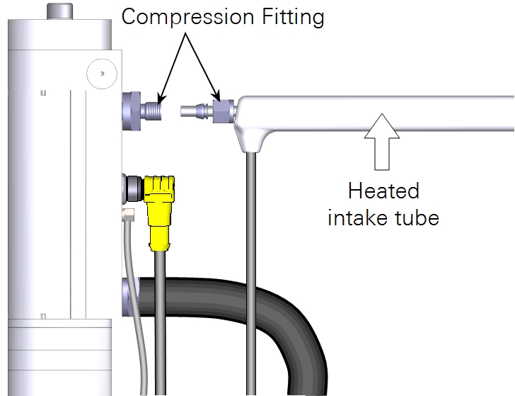
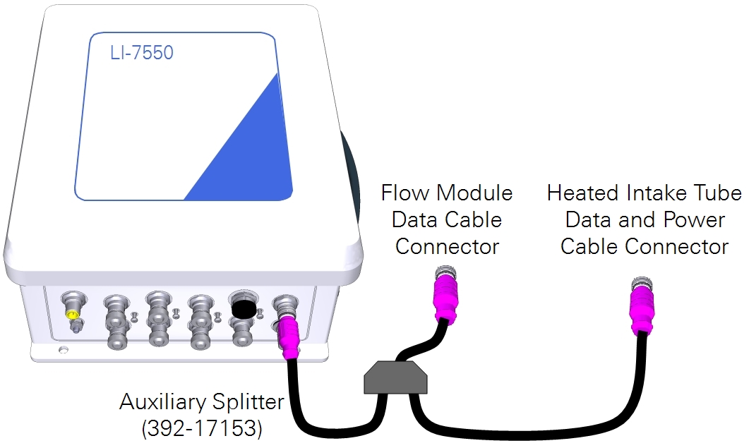
The heated intake tube cable connects to the AUXILIARY connector on the LI-7550 using the auxiliary splitter cable (part number 392-17153), as shown in Figure 2‑2. Contact LI-COR if you want to use the heated intake tube on an LI-7550 manufactured before June 6, 2014 (serial numbers AIU-1279 and lower)
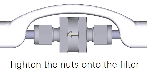
Installing the 2-micron particulate filter
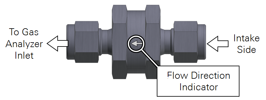
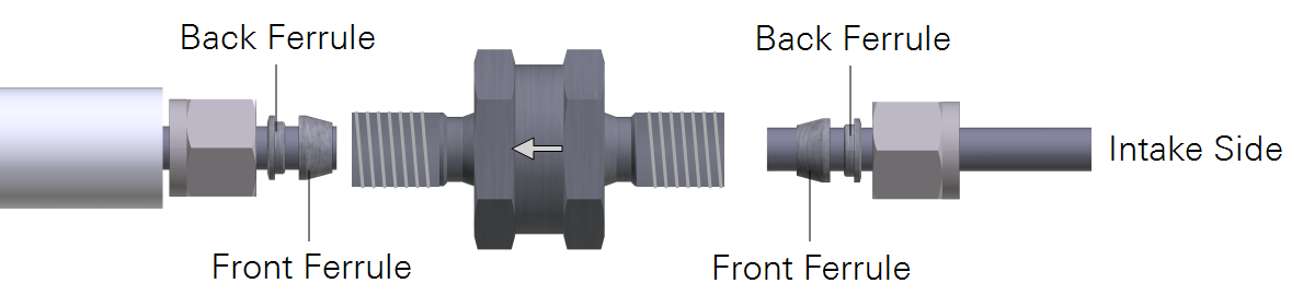
An optional 2-micron Swagelok® filter (part number 9972-073) can be placed in line on the inlet tube. It will reduce the amount of dust that enters the gas analyzer optical cell. Under normal conditions, the filter should extend the amount of time that can pass before you need to clean the optical cell. The filter is recommended in environments that have airborne dust and pollen that can contaminate the optical cell.
Important: The filter does not eliminate the need to regularly clean the optics. Regular cleaning is required in order to prevent measurement drift that can occur when certain kinds of contaminants accumulate on the cell windows.
- The filter will increase the power requirements of your system. As the filter becomes dirty, the flow module will use more power to maintain the same flow rate.
- The filter may affect H2O frequency response, especially when it is dirty. This can be addressed with additional frequency response corrections during data processing, but it is preferable to operate the system with a clean filter.
- The effectiveness of the filter depends upon the site conditions, overall level of dust in the air, and the characteristics of the dust (fine vs. coarse dust particles).
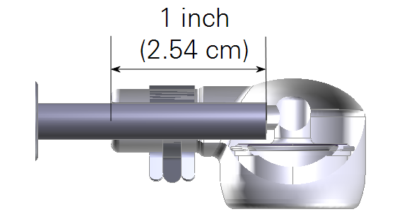
Installing the air inlet
The air intake kit includes a flexible air inlet, screen, and hose clamp. It also has a spare screen and hose clamp. The intake cap attaches to either the insulated intake tube or the heated intake tube. If using the insulated intake tube with the particulate filter, install the tube extension to the intake side of the filter. To install the intake cap, insert it into the hose clamp, expand the clamp with a pliers, then slip the air inlet over the tube. The tube will insert about 2.5 cm into the inlet.
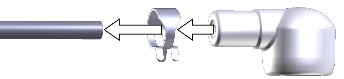
Note: Do not expand the hose clamp more than necessary. Doing so can permanently deform the clamp.
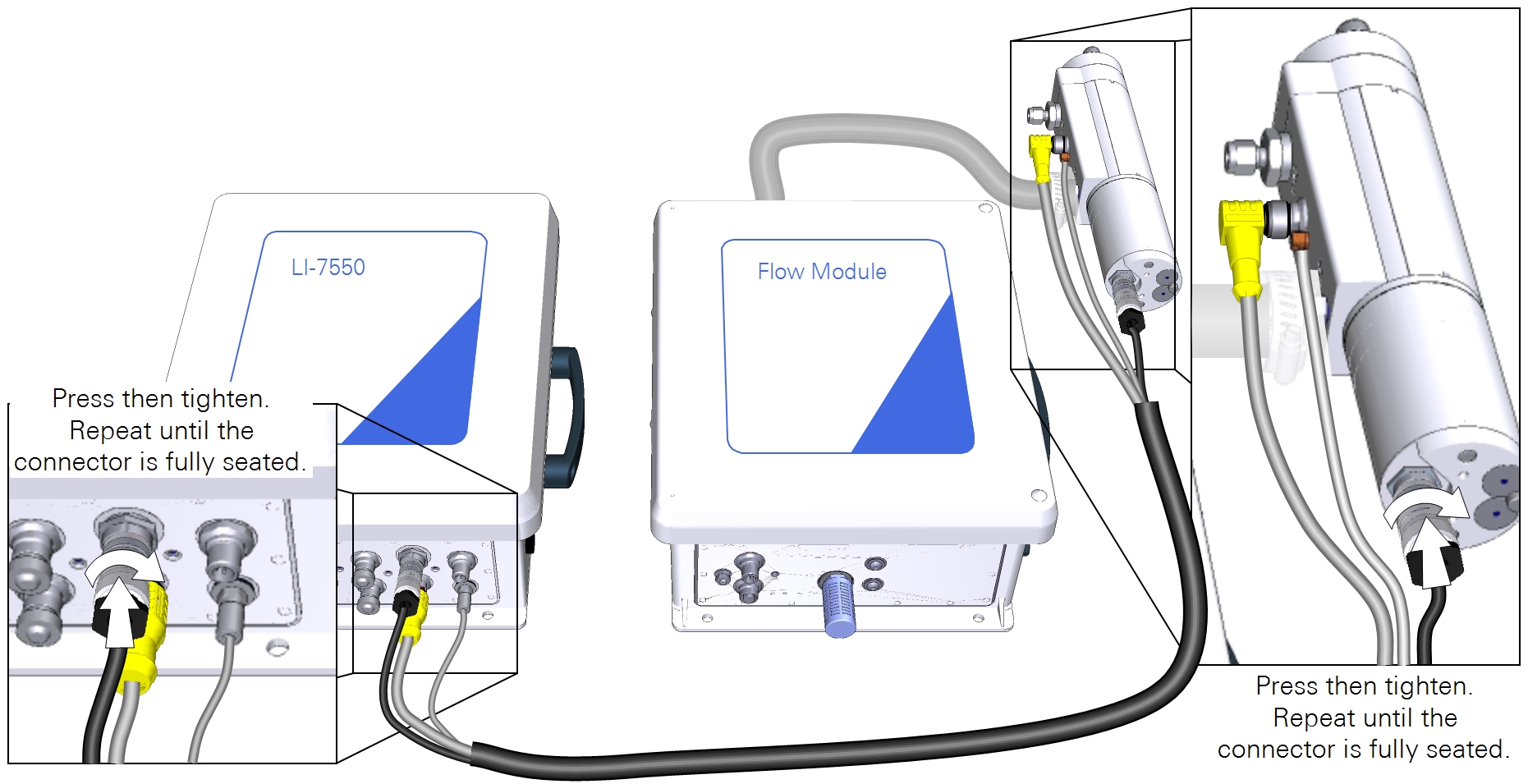
Connecting the analyzer data cables
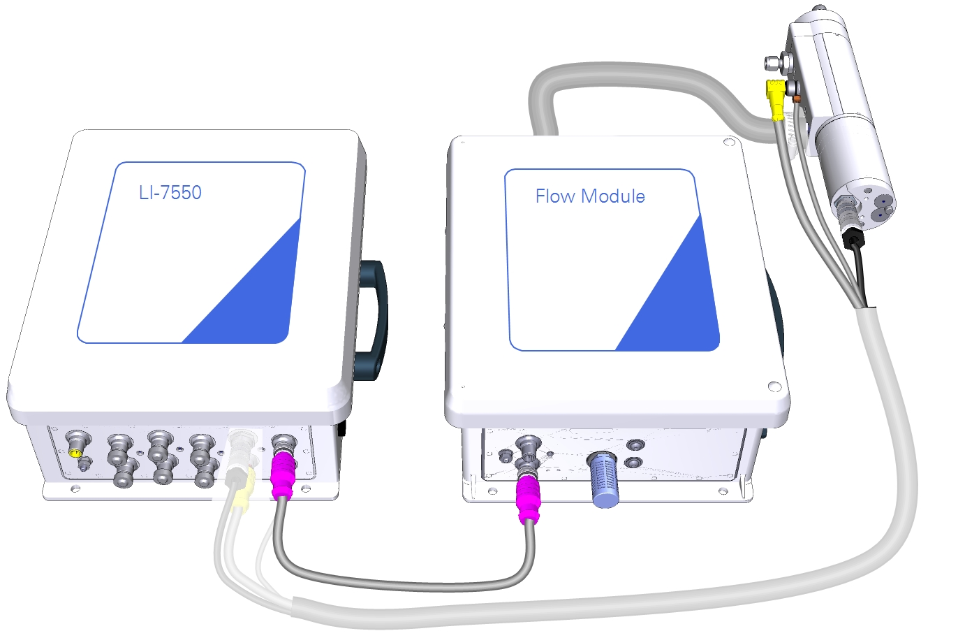
The cable bundle has two cables and a tube. The cable with a yellow connector and a 90° bend connects to the head between the air inlet and outlet; the other end connects to the SENSOR connector on the LI-7550. The cable with stainless steel collars connects to the bottom of the head; the other end connects to the IRGA connector on the LI-7550. Align the notches on the cable connectors, then push in and turn the connector clockwise until it is tight. Continue to push in while tightening the connector until the connector is fully seated. The gasket must be compressed to ensure a watertight seal. The tube attaches to the hose barb between the air inlet and outlet on the head. The other end connects to the quick-connect labeled PRESSURE on the LI-7550. See Figure 2‑5 for details.
Connecting the flow module data cable
The 5-meter accessory cable (part number 392-10092) has male and female connectors that attach to the flow module and LI-7550 connector panels at the connectors labeled ACCESSORY.
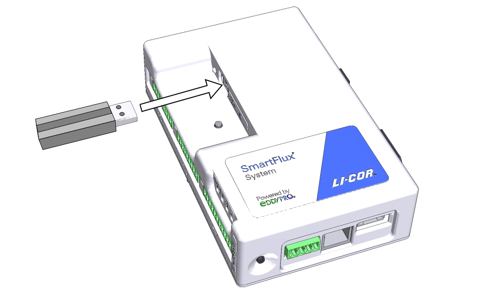
Installing the LI-7550 USB drive
Open the cover to the LI-7550 and insert the USB drive from the spares kit into the USB port. Close and latch the cover.
Important: A USB drive must be installed in the LI-7550 to log data. Beginning with SmartFlux firmware v2.2.8, a USB drive must also be installed in the SmartFlux 2 System to ensure successful data processing. A full dataset is stored on both USB drives.
Preparing the enclosure
Start by assembling the enclosure hardware.
Installing the system power supply cable
Connect the main power supply conduit to the small opening in the enclosure. Orient the lock-nut teeth so that they make contact with the enclosure surface. Connect the main power supply wires to terminals 3, 4 and 5.
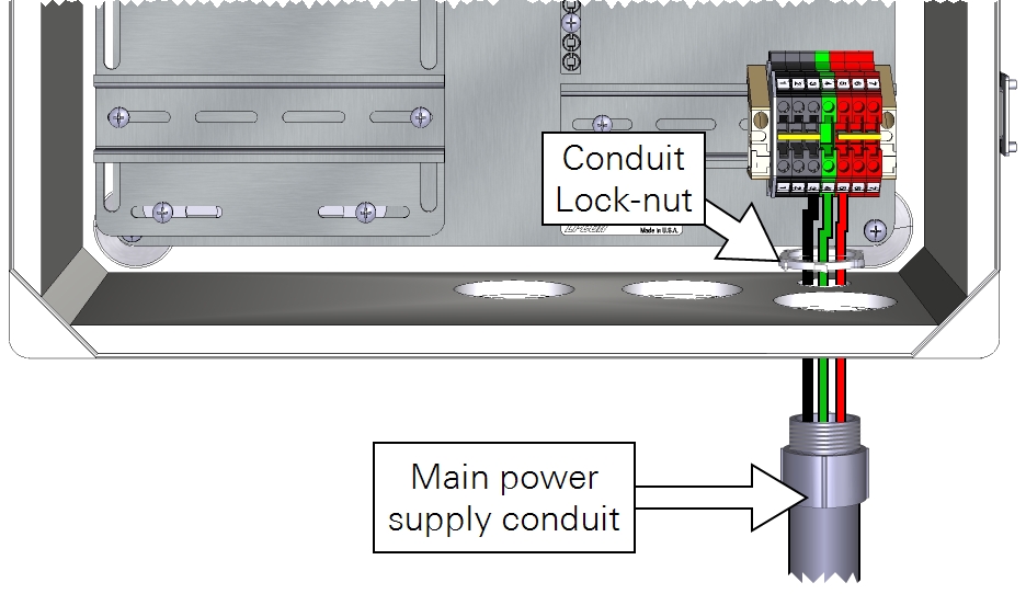
As a good practice, be sure that your power cable is not connected to a power source until the wiring is complete. Keep the breakers in the OFF position until you are ready to power up the system.
| From | Wire Color | To |
|---|---|---|
| Main power (-) | black | DIN Terminal 3 (bottom) |
| Earth ground | green | DIN Terminal 4 (bottom) |
| Main power (+) | red | DIN Terminal 5 (bottom) |
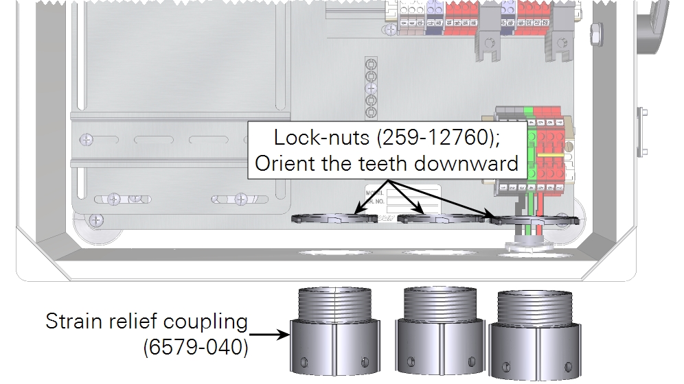
In both the eddy covariance system enclosure (7900-050) and the Biomet Data Acquisition System enclosure (7900-126), install the three strain-relief couplings in the three bottom openings.
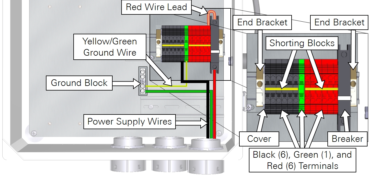
In the eddy covariance system enclosure (7900-050), install the Power Distribution Kit (7900-235) on the raised DIN rail. Connect the red wire lead between the top of the breaker and top right red terminal. Install one shorting block to connect all black terminals and another to connect all red terminals.
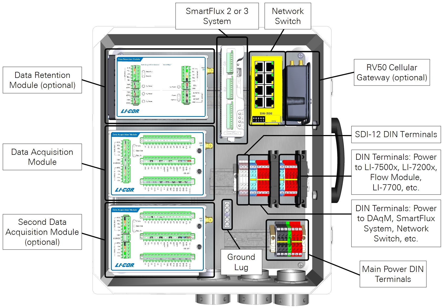
Preparing the SmartFlux System and network switch
Follow the steps below when installing the SmartFlux System in the 7900-050 Eddy Covariance System Enclosure or 7900-126 Biomet Data Acquisition System Enclosure. If you are using a different enclosure, connect the power and data cables similarly to what is described here.
Install the USB drive
Data are recorded to the USB drive. Install the USB drive in the USB port on the SmartFlux System.
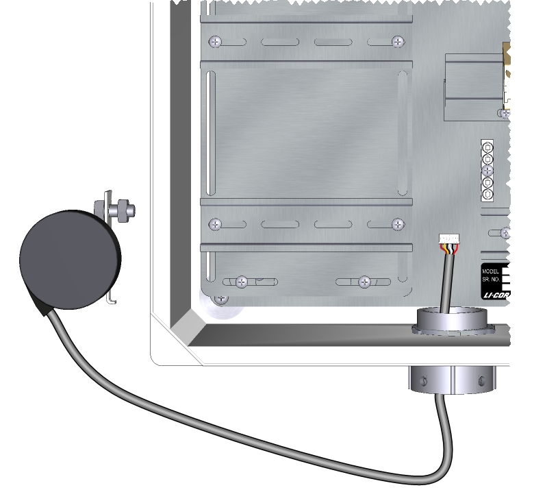
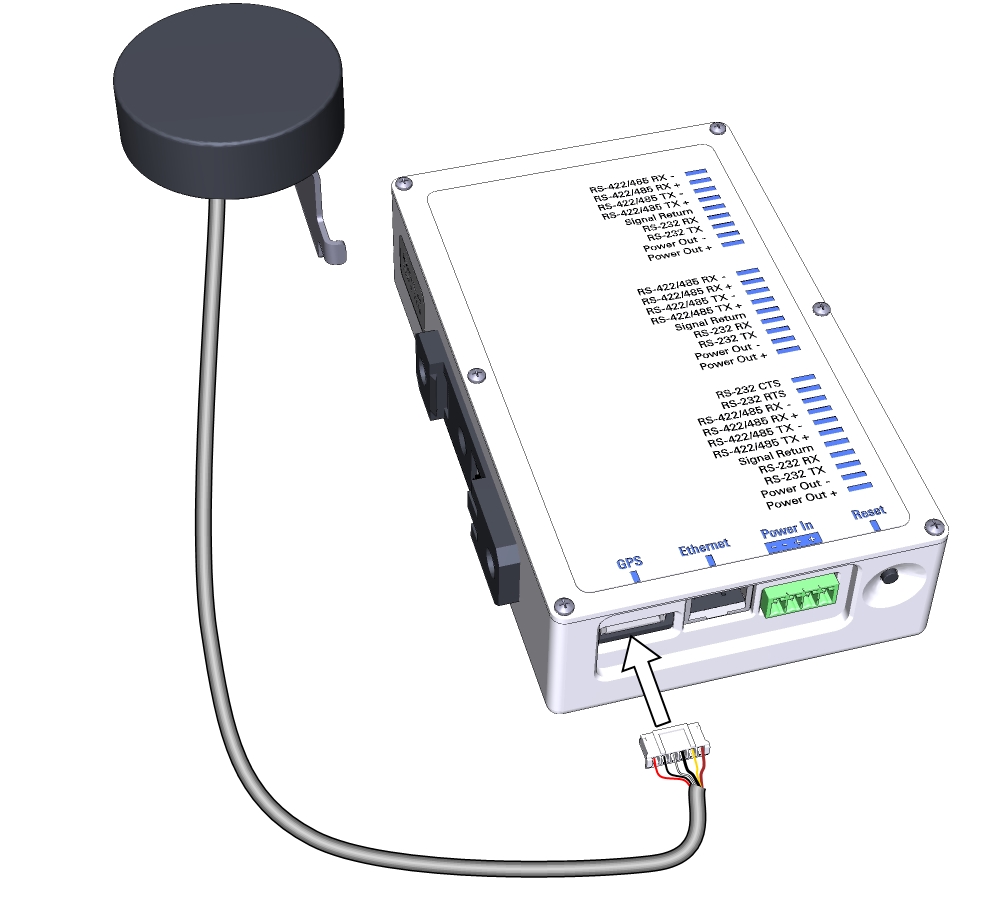
Connect the GPS antenna cable
Route the GPS cable through the left opening at the bottom of the enclosure and plug it into the GPS port on the SmartFlux System.
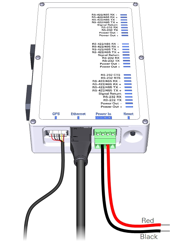
Connect power wires and the Ethernet cable to the SmartFlux System
Connect wire leads to the positive and negative terminals on the SmartFlux System. The black lead connects to negative (-), the red lead connects to positive (+). Plug in the 30 cm Ethernet cable that came with the SmartFlux System. There are two connections for positive (+) and two for negative (-). Use only one pair of +/- terminals.
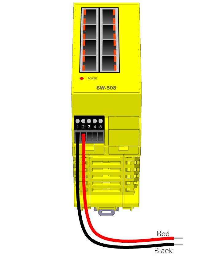
Connect power wires to the Brainboxes network switch
Power wires connect to the positive and negative terminals on the switch. The black lead connects to terminal 1 (-), the red lead connects to terminal 2 (+).
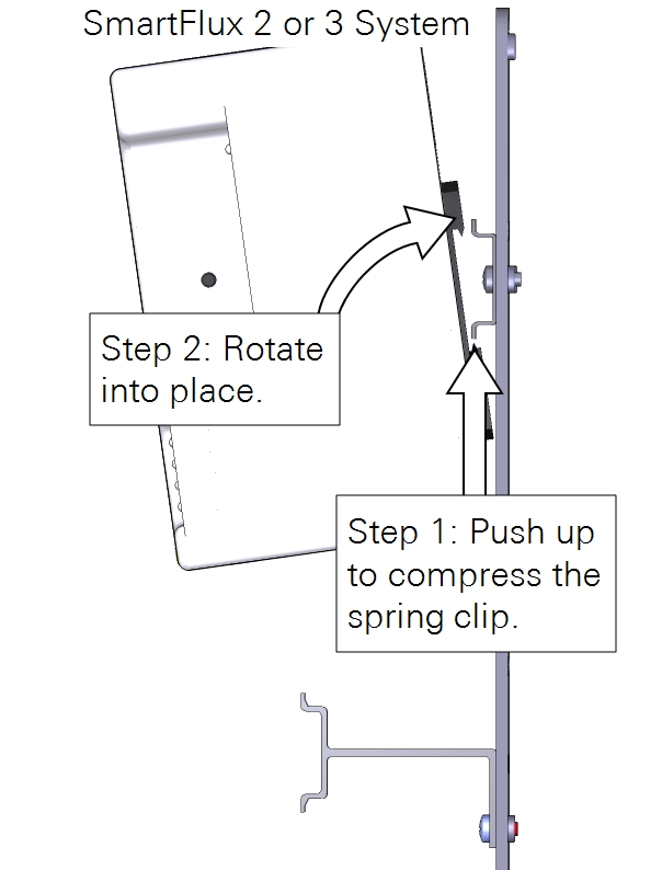
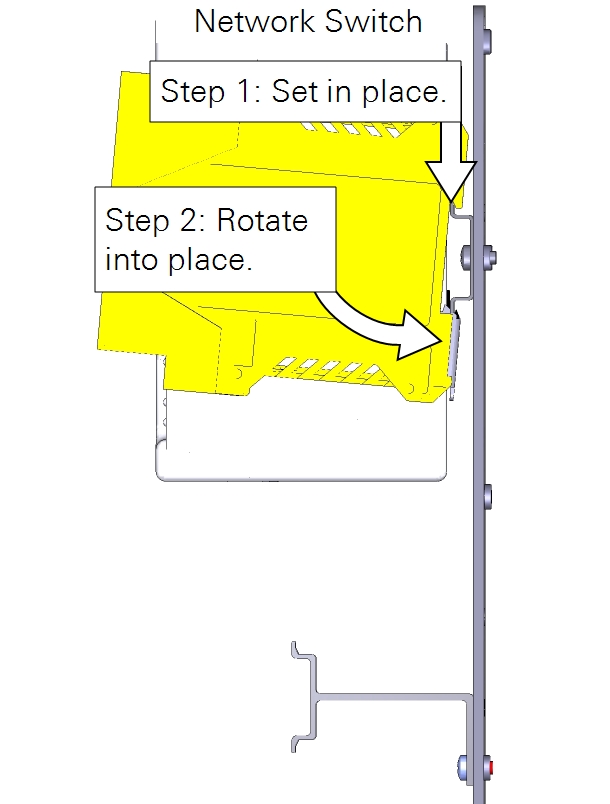
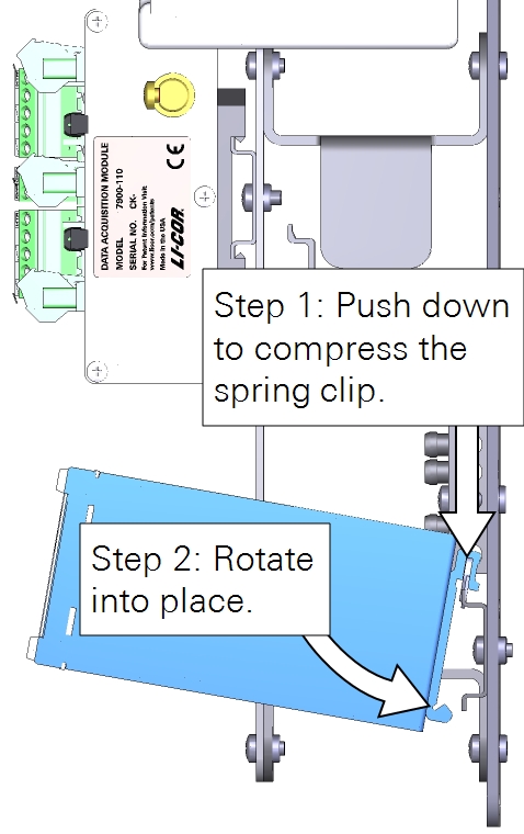
Installing the SmartFlux System and network switch
Install the SmartFlux 2 or 3 System onto left side of the upper-right DIN rail. Insert the spring-loaded clip on the bottom edge of the DIN rail and compress the spring. Rotate it into place. Mount the switch next to it.
Connecting component power wires
The 7900-050 and 7900-126 enclosures present different wiring options. Be sure the power supplied to the enclosure is within the upper voltage limits of attached components, but capable of providing 4 to 5 amps. Keep the breaker OFF while connecting power wires.
7900-050 Eddy Covariance System Enclosure
With the 7900-050 enclosure, keep the breaker OFF. Connect the positive (+) leads to the red terminals and the negative leads (-) to the black terminals for all components of the system. Proceed to Connecting gas analyzer and flow module power wires.
7900-126 Biomet Data Acquisition System Enclosure
With the 7900-126 enclosure, each component is powered individually from the power supply terminals, the DC-DC converter, or the DRM power outputs. 24-volt and 12-volt power supplies will be wired differently.
Caution: Do not short circuit the power supplies. For example, avoid connecting the V4 POWER OUT terminals from a Data Retention Module to the Power In terminals on a device that is powered from another power supply. Doing so will damage components and may present risk of a fire.
Select the power supply option that describes your system:
- 24 VDC power supply with Data Retention Module. This configuration uses the 24 volt output from a SunWize solar power supply. The DRM provides voltage regulation for devices that are not compatible with the 24 volt power supply.
- 12 VDC power supply with Data Retention Module. With a 12 volt power supply, no voltage regulator is needed.
- 12 VDC power supply with no Data Retention Module. With a 12 volt power supply, no voltage regulator is needed.
- 24 VDC power supply with the TDK-Lambda DC-DC converter. With a 24 volt power supply and no Data Retention Module, the TDK-Lambda voltage regulator should be used to power devices that have maximum power supply limits lower than 24 VDC.
24 VDC power supply with Data Retention Module
With a 24 VDC power supply, the DRM V3 power outputs can be used to power low-voltage components through the left 10-amp breaker and DIN terminals. Components powered in this manner include the network switch, PhenoCam, cellular gateway, satellite modem, CNF4 heater and ventilation unit (for the CNR4), or self-calibrating soil heat flux plates (HFP01SC).
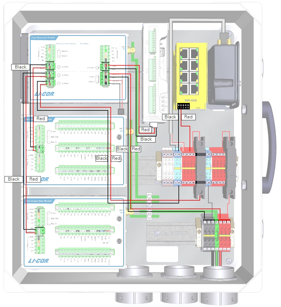
| From | Wire Color | To |
|---|---|---|
| DRM and DAqM Ground Lugs | yellow/green | Enclosure Ground Lug |
| DIN Terminal 1 (top) | black | DRM POWER IN GND (-) |
| DIN Terminal 5 (top) | red | DRM POWER IN +9-30 VDC (+) |
| DRM V1 Power GND | black | DAqM 1 GND (-) |
| DRM V1 Power +12V1 | red | DAqM 1 PWR (+) |
| DRM V2 Power GND | black | DAqM 2 GND (-) |
| DRM V2 Power +12V2 | red | DAqM 2 PWR (+) |
| DRM V3 Power GND | black | DIN Terminal 12 (bottom) |
| DRM V3 Power +12V3 | red | Left Breaker (bottom) |
| DRM V4 Power GND | black | SmartFlux System (-) |
| DRM V4 Power +12 V4 | red | SmartFlux System (+) |
| DIN Terminal 12 (top) | black | Network Switch (-) |
| DIN Terminal 15 (top) | red | Network Switch (+) |
| DIN Terminal 11 (top) | black | Cellular/Satellite Modem (-) |
| DIN Terminal 13 (top) | red/white | Cellular/Satellite Modem (+) |

12 VDC power supply with Data Retention Module
With a 12 VDC power supply, you do not need to connect the DRM power out to the breaker or terminal strips because 12 VDC is within the limits of all components.
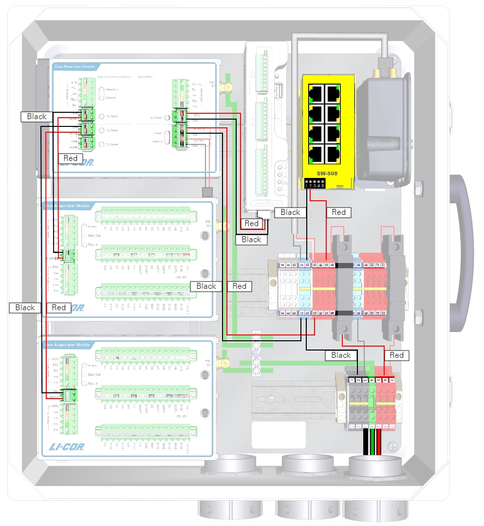
| From | Wire Color | To |
|---|---|---|
| DRM and DAqM Ground Lugs | yellow/green | Enclosure Ground Lug |
| DIN Terminal 11 (bottom) | black | DRM POWER IN GND (-) |
| DIN Terminal 13 (bottom) | red | DRM POWER IN +9-30 VDC (+) |
| DRM V1 Power GND | black | DAqM 1 GND (-) |
| DRM V1 Power +12V1 | red | DAqM 1 PWR (+) |
| DRM V2 Power GND | black | DAqM 2 GND(-) |
| DRM V2 Power +12V2 | red | DAqM 2 PWR (+) |
| DRM V4 Power GND | black | SmartFlux System (-) |
| DRM V4 Power +12 V4 | red | SmartFlux System (+) |
| DIN Terminal 12 (top) | black | Network Switch (-) |
| DIN Terminal 15 (top) | red | Network Switch (+) |
| DIN Terminal 11 (top) | black | Cellular/Satellite Modem (-) |
| DIN Terminal 13 (top) | red/white | Cellular/Satellite Modem (+) |

12 VDC power supply with no Data Retention Module
If your system does not have a Data Retention Module, the SmartFlux System will be powered from the enclosure power terminals rather than the DRM power outputs.
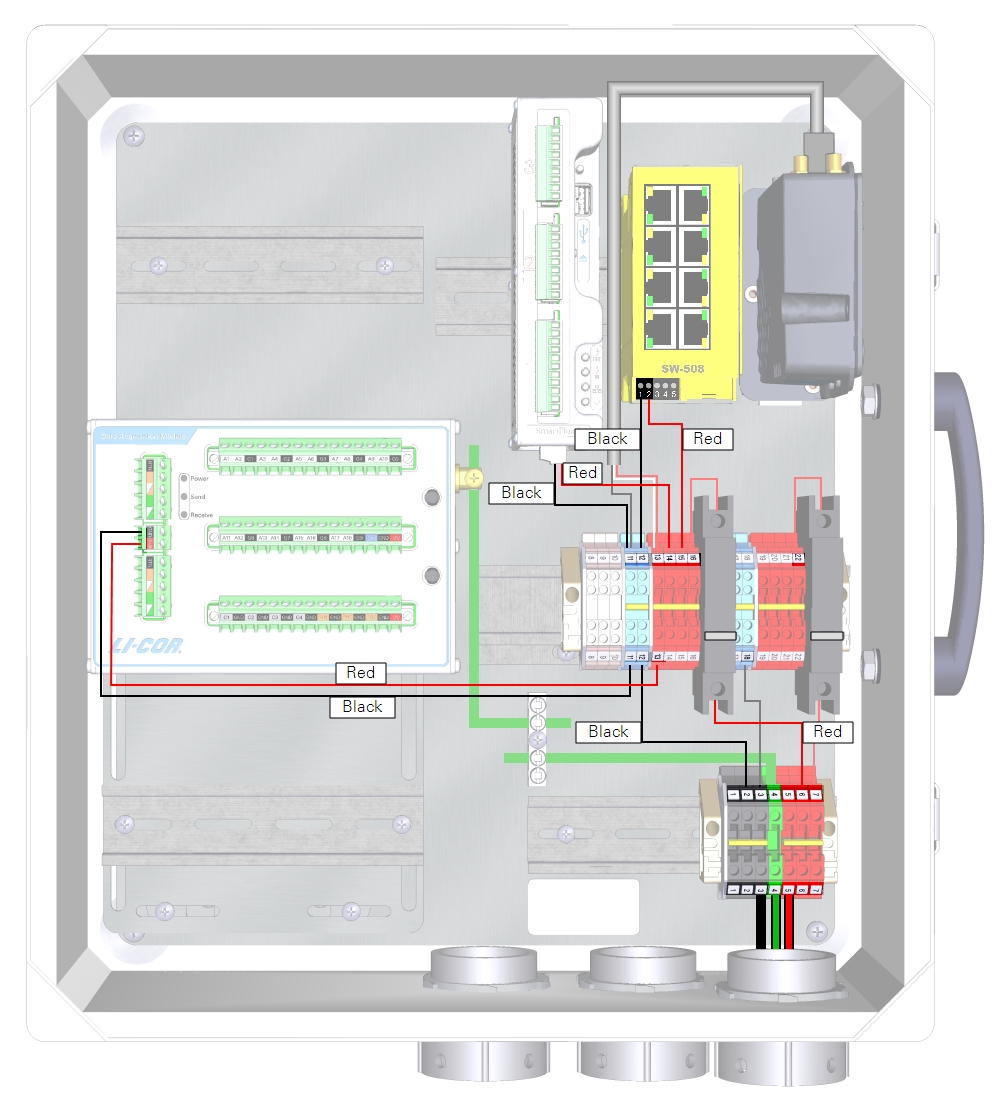
| From | Wire Color | To |
|---|---|---|
| DRM and DAqM Ground Lugs | yellow/green | Enclosure Ground Lug |
| DIN Terminal 11 (bottom) | black | DAqM GND (-) |
| DIN Terminal 13 (bottom) | red | DAqM PWR (+) |
| DIN Terminal 11 (top) | black | SmartFlux System GND (-) |
| DIN Terminal 14 (top) | red | SmartFlux System (+) |
| DIN Terminal 12 (top) | black | Network Switch (-) |
| DIN Terminal 15 (top) | red | Network Switch (+) |
| DIN Terminal 11 (top) | black | Cellular/Satellite Modem (-) |
| DIN Terminal 13 (top) | red/white | Cellular/Satellite Modem (+) |

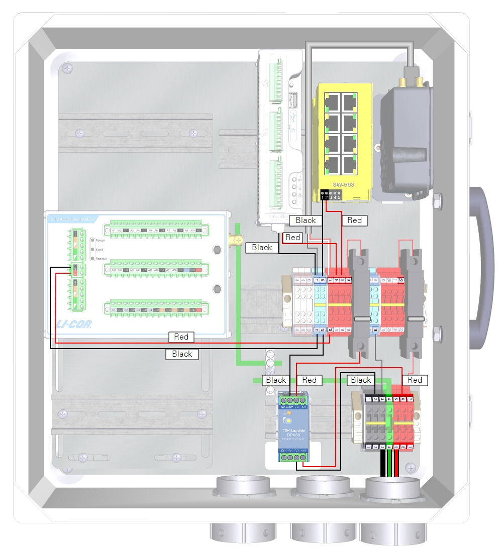
24 VDC power supply with the TDK-Lambda DC-DC converter
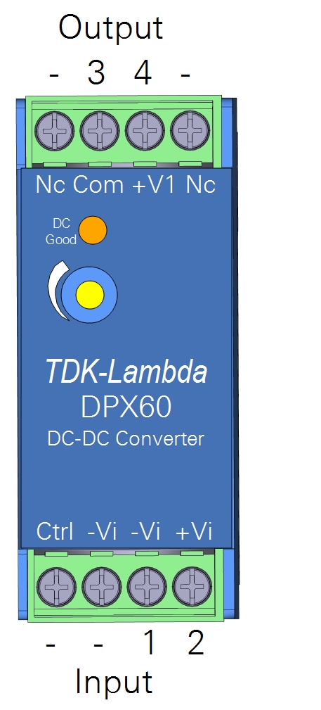
The TDK-Lambda DC-DC Converter (model DPX60) regulates output voltage to about 12 VDC, which makes it possible to power low-voltage devices from a 24 VDC solar power supply. The DC-DC converter should be used to power the left 10-amp accessory breaker (and the SmartFlux System) if you have a 24 VDC power supply and no DRM.
Full documentation for the TDK-Lambda DC-DC converter is available from the manufacturer's website: us.tdk-lambda.com/lp/products/dpx-series.htm.
The DC-DC converter mounts to a DIN rail in the lower right of the enclosure. Compress the spring the in the DIN clip and rotate the converter into place.
Connect the incoming power to the charge controller Input terminals (-Vi and +Vi) and connect the regulated power from the charge controller output terminals (COM and +V1) to the left breaker and DIN terminal 12. See Figure 2‑10 and Table 2‑5 for details.

Connecting gas analyzer and flow module power wires
Power wires for the gas analyzer and flow module connect to terminals in the enclosure. With the eddy covariance system enclosure (7900-050) and Power Distribution Kit (7900-235), connect the red and black power wires leads to corresponding red and black terminals. With the Biomet Data Acquisition System enclosure (7900-126), connect the leads as described in Table 2‑6.
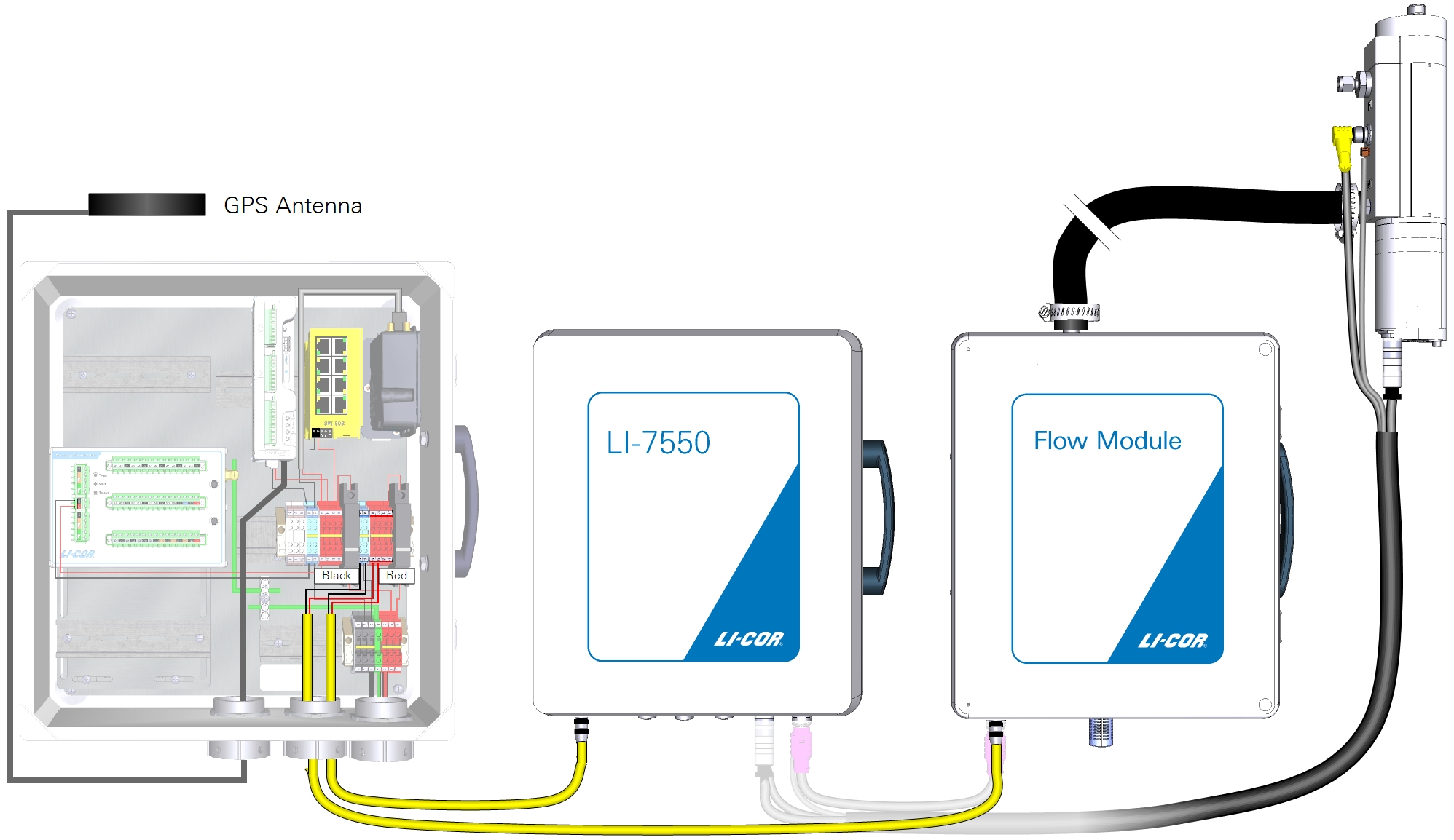
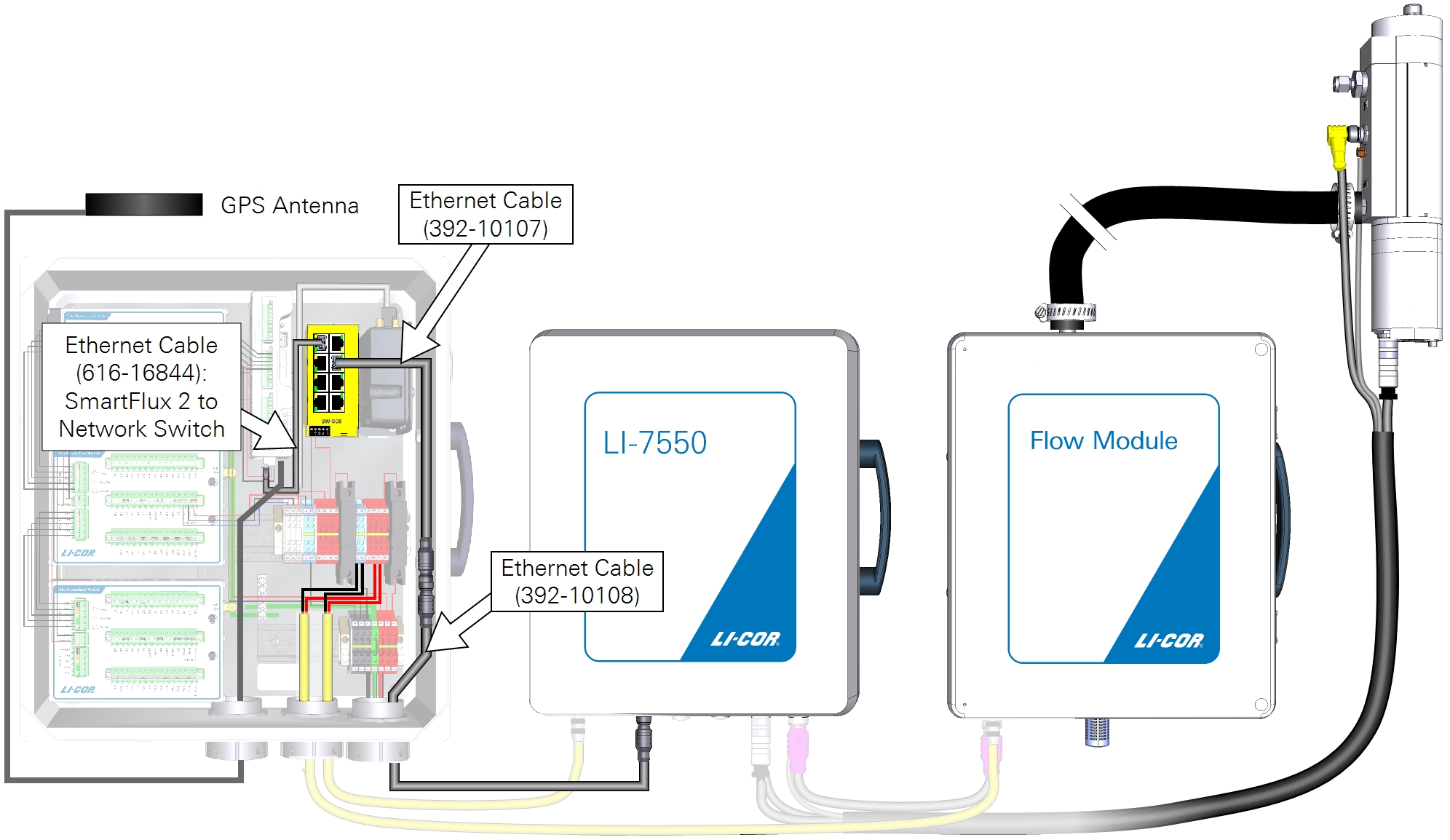
Connecting Ethernet cables
Ethernet cables connect the SmartFlux 2 System and LI-7550 to the network switch. Vacant ports on the network switch are for other networked components, such as the cellular gateway, PhenoCam, LI-7700, or connecting a PC.
Connecting sonic anemometer data and power cables
The SmartFlux 2 System can record digital data from a number of sonic anemometer models. These are described below. Power for the sonic anemometer is provided through the SmartFlux System.
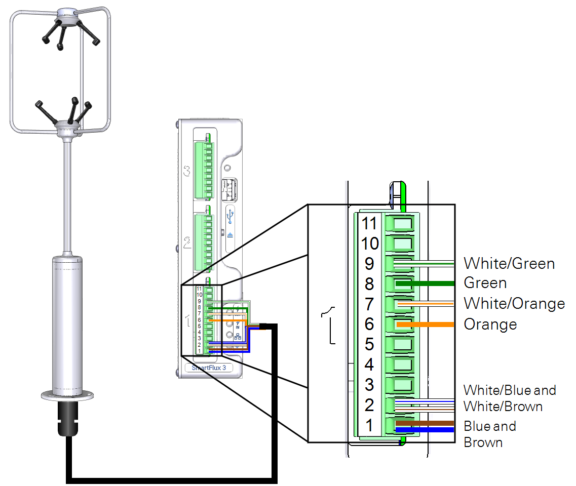
Gill WindMaster or WindMaster Pro
Part Number: 7900-415-x
A combined power and data cable is available for the Gill WindMaster/Pro sonic anemometers. The sonic anemometer will be configured automatically when it is connected to the SmartFlux System and selected in the software. The cable connects to one of the digital I/O ports on the SmartFlux System (port 1 recommended).
| SmartFlux Terminal | SmartFlux Label | Wire Color |
|---|---|---|
| 9 | RS-422/485 RX- | White/Green |
| 8 | RS-422/485 RX+ | Green |
| 7 | RS-422/485 TX- | White/Orange |
| 6 | RS-422/485 TX+ | Orange |
| 2 | Power to Anemometer (-) | White/Blue and White/Brown |
| 1 | Power to Anemometer (+) | Blue and Brown |
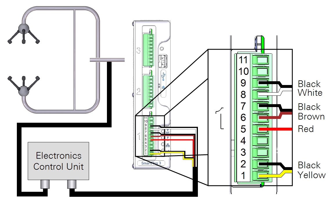
Gill HS-50 or R3-50
Part Number: 7900-445-x
A combined power and data cable is available for the Gill HS-50 or R3-50 sonic anemometers. The sonic anemometer will be configured automatically when it is connected to the SmartFlux System and selected in the software. The cable connects to one of the digital I/O ports on the SmartFlux System (port 1 recommended). The R3 uses the same cable as the HS, but the cable connects to the base of the R3 rather than the electronics control unit.
Important: At least 13 VDC must be supplied when using a 50 meter power cable because of voltage drops.
| SmartFlux Terminal | SmartFlux Label | Wire Color |
|---|---|---|
| 9 | RS-422/485 RX- | Black (bundled with white) |
| 8 | RS-422/485 RX+ | White |
| 7 | RS-422/485 TX- | Black (bundled with brown |
| 6 | RS-422/485 TX+ | Brown |
| 5 | Signal Return | Red |
| 2 | Power Out (-) | Black (bundled with yellow) |
| 1 | Power Out (+) | Yellow |
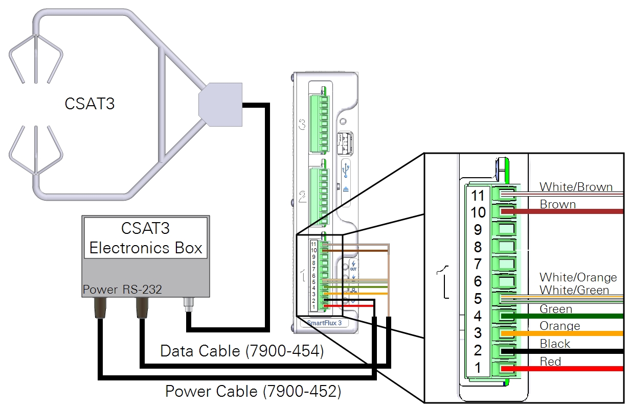
Campbell Scientific CSAT3
Data Cable: 7900-454-x;
Power Cable: 7900-452-x
Power and data cables are available for the Campbell Scientific, Inc. CSAT3 sonic anemometers. The sonic anemometer will be configured automatically when it is connected to the SmartFlux System and selected in the software. The cable connects to digital I/O Port 1 on the SmartFlux System.
Important: The CSAT3 requires 10 to 16 VDC. Supplying an incoming 24 VDC to the SmartFlux System will damage a CSAT3.
| SmartFlux Terminal | SmartFlux Label | Wire Color |
|---|---|---|
| 11 | CTS | White/Brown |
| 10 | RTS | Brown |
| 5 | Signal Return | White/Orange and White/Green |
| 4 | RS-232 RX | Green |
| 3 | RS-232 TX | Orange |
| 2 | Power Out (-) | Black |
| 1 | Power Out (+) | Red |
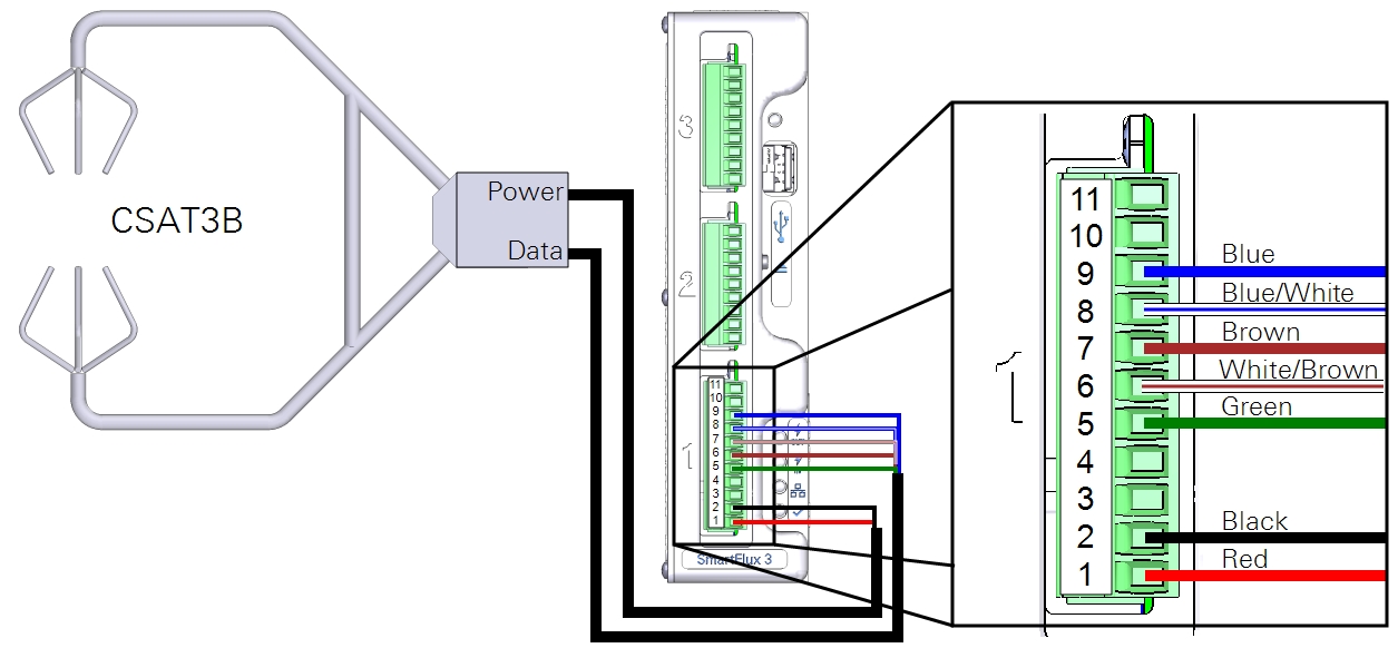
Campbell Scientific CSAT3B
See CSAT3B and CSAT3 for details on the USB connection.
Data Cable: 7900-464-x; Power Cable: 7900-462-x
You can use a Campbell Scientific, Inc. CSAT3B sonic anemometer with the data cable (part number 7900-464-x) and power cable (part number 7900-462-x). The CSAT3B anemometer must be configured before it will work with the SmartFlux System. Using the Campbell Scientific Device Configuration Utility, apply the following settings.
| Parameter Name | Correct Setting |
|---|---|
| Communication Protocol | RS-485 Enabled |
| RS-485 Baud Rate | 115200 |
| Unprompted Output Port | RS-485 Port |
| Unprompted Output Rate | 50 Hz |
| Operating Mode | Unprompted Output - No Filters |
The cable connects to one of the digital I/O ports on the SmartFlux System (port 1 recommended).
| SmartFlux Terminal | SmartFlux Label | Wire Color |
|---|---|---|
| 9 | RS-422/485 RX- | Blue |
| 8 | RS-422/485 RX+ | Blue/White |
| 7 | RS-422/485 TX- | Brown |
| 6 | RS-422/485 TX+ | White/Brown |
| 5 | Signal Return | Green |
| 2 | Power Out (-) | Black |
| 1 | Power Out (+) | Red |
Metek Cage or Class-A
Cage Cable: 7900-482-x; Class-A Cable: 7900-492-x
A combined power and data cable is available for the Metek Multi-Path Class A and Cage sonic anemometers. The Class A has an electronic box between the head and SmartFlux; the Cage connects directly. The anemometer will be configured automatically when it is connected to the SmartFlux System and selected in software. The cable connects to one of the digital I/O ports on the SmartFlux System (port 1 recommended).
| SmartFlux Terminal | SmartFlux Label | Wire color |
|---|---|---|
| 9 | RS-422/485 RX- | Green |
| 8 | RS-422/485 RX+ | Yellow |
| 7 | RS-422/485 TX- | Brown |
| 6 | RS-422/485 TX+ | White |
| 2 | Power Out (-) | Pink |
| 1 | Power Out (+) | Gray |
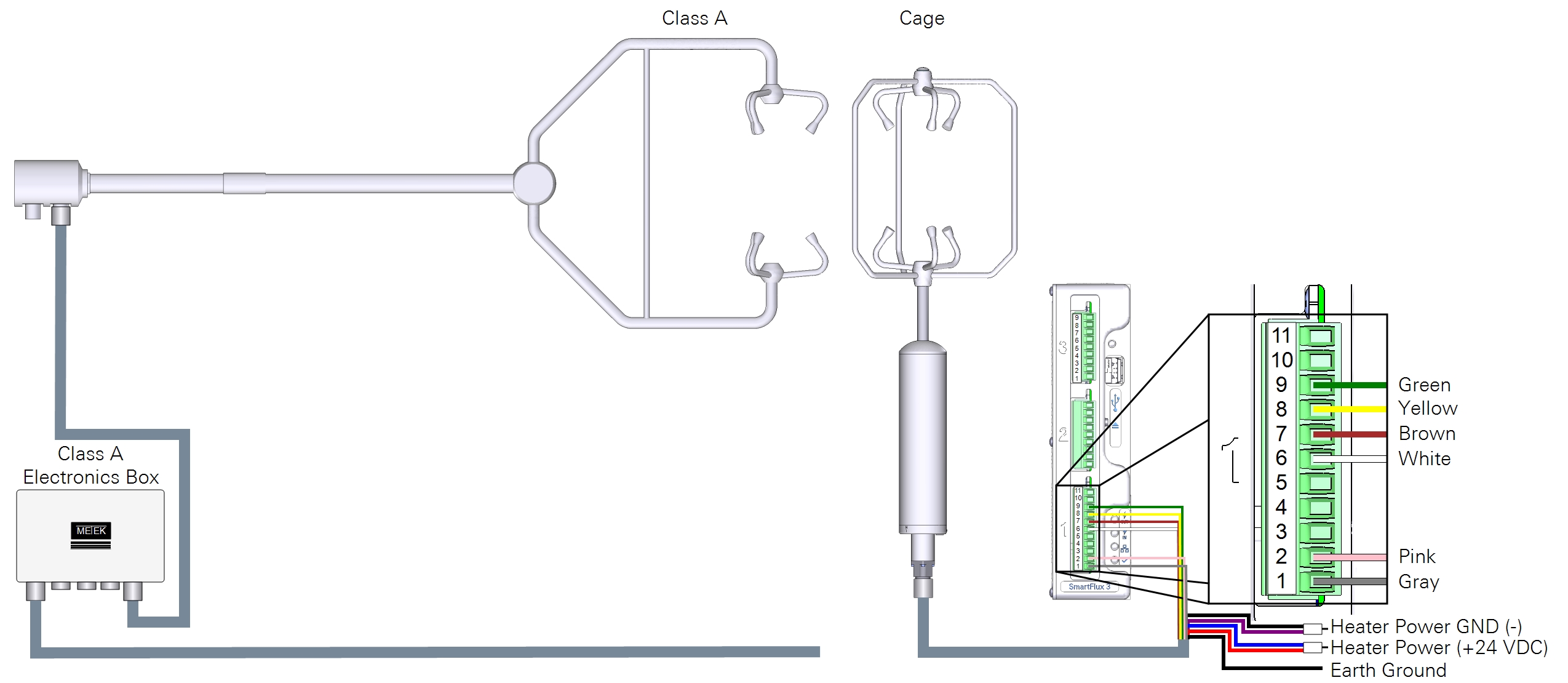
Heaters are powered by the system power supply, typically.
| Heater Wire | Color | Connects to |
|---|---|---|
| Power GND | Black | Purple | Terminals 1 to 3 |
| Power (+24 VDC) | Blue | Red | Terminals 5 to 7 |
| Ground | System ground |
Important: Refer to the Metek MP instruction manuals for details about operating the heater in low-voltage and over-voltage conditions.
RM Young 81000x
Part Number: 7900-472-x
A combined power and data cable is available for the RM Young 81000 series sonic anemometers. The anemometer will be configured automatically when it is connected to the SmartFlux System and selected in software. The cable connects to one of the digital I/O ports on the SmartFlux System (port 1 recommended).
| SmartFlux Terminal | SmartFlux Label | RM Young Label | Wire Color |
|---|---|---|---|
| 9 | RS-422/485 RX- | B1 | White/Green |
| 8 | RS-422/485 RX+ | A1 | Green |
| 7 | RS-422/485 TX- | B2 (RX) | White/Orange |
| 6 | RS-422/485 TX+ | A2 (TX) | Orange |
| 5 | Signal Return | SREF | White/Brown |
| 2 | Power Out (-) | PWR REF | White/Blue |
| 1 | Power Out (+) | +PWR | Blue |
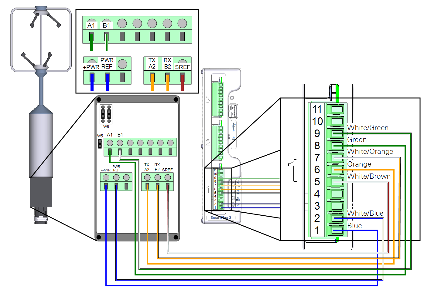
There are three shorting block jumpers in the anemometer that must be in the correct position. Two jumpers connect each pair of middle pins at W6. One jumper connects the two pins at W5.