Tips for success
This section provides some tips for operating the instrument is difficult site conditions.
Site maintenance schedule
A good site maintenance plan will help ensure more complete data coverage. Follow these recommendations when you first deploy the site.
When you first deploy the instrument:
Check the flow drive percent and record it. This will help you determine if the intake filter needs to be cleaned.
Check the signal strength and record this for a baseline. This will help you determine when the optics should be cleaned.
Every day or every few days:
Check the overall performance of the instruments, including the measured values and diagnostic information. This will ensure that you don't lose data (or that you lose less data) if something is wrong.
Check the measured values. Air temperature, pressure, sonic temperature, dew point, gas concentrations, covariances and fluxes. Any unexpected readings may indicate an issue.
Check the diagnostics. Signal strength, detector temperature, chopper housing temperature, and thermocouples.
Once per week:
After installing the new system, start by checking the signal strength once per week. There is no absolute guideline for good or bad signal strength, but 100% indicates very clean optics and optimal performance from the analyzer. If the signal strength has dropped, it is a good idea to clean the optics. For most sites, the maintenance frequency is once every 3-4 weeks. The signal strength limit, below which the instrument readings are compromised, varies due to the spectral characteristics of the contaminants involved. Typically, signal strength values should be maintained in the upper 90’s for consistent performance. Delta signal strength is a variable that provides an indication of the drift associated with contamination. See CO2 signal strength for more information.
Once per month:
Check the zero and span. As you become familiar with your instrument, you will probably find that this does not need to be checked as often.
If you are not using an intake filter, clean the upper and lower windows of the analyzer (see Cleaning the optics).
Download all your data and store it to an archive.
Check cables for damage. Tighten any loose cable connections.
Check tubing for kinks or damage (both the pressure and flow tubes). If either tube is restricted, either replace it or reposition it so that the flow does not become restricted.
Every six months:
If your instrument is in a humid environment, replace the head chemicals.
Once per year:
Replace the head chemicals.
Clean or replace any air filters.
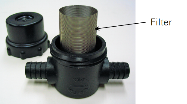
Filtering the air inlet
The LI-7200RS is very stable when the optics are kept clean. However, with continuous operation in dirty environments without cell cleaning, you may see mean concentration changes of up to several percent or more. Properly cleaning the optical bench and windows periodically will significantly reduce or eliminate such changes.
In situations where fine particle filtering is required to maintain acceptable data quality, we recommend the 2-micron filter that is included with the instrument. If additional filtration is needed, a restrictive single-micron filter can be used (LI-COR part number 9967-008). The Flow Module was designed specifically for low-power operation, and cannot be used with a single-micron filter. If you use a single micron-filter. an external pump will be required.
Cleaning the optics
Additional action is usually not required after cleaning. If possible, however, flow dry, CO2-free gas through the cell and check the zeros. If they are not close, the windows may need further cleaning, or the internal chemical bottles may need to be replaced.
If you decide to recalibrate instead of cleaning, or cannot seem to clean the windows sufficiently (and are sure the cause is not depleted chemical bottles) then you should perform both zero and span. Contamination that causes a zero shift will also usually cause a slight span shift too.
Operating in environments with high-frequency vibrations
The LI-7200RS is vibration sensitive to frequencies of 150 Hz ± the bandwidth. Thus, if the bandwidth is 10 Hz, the frequency problem range is 140 to 160 Hz (and upper harmonics). The instrument is completely insensitive to vibrations slower than this, and very slightly sensitive at frequencies higher than this.
For land-based installations, the most likely source of vibrational problems would be on a tower with tight guy wires. For other settings (aircraft, ships, etc.) where there may be vibrations in the problem range, you should try to minimize the problem through alternative mounting attachments. When using an intake tube longer than 50 cm, we recommend that you secure the tube to avoid excessive vibration and torque, as shown in Securing the intake tube.
Operating in cold weather (<5 °C)
The instrument has a temperature setting that reduces the dissipation of heat in cold weather. We recommend that you change the setting when the average ambient temperature drops below 5 °C. See Setting the operating temperature range for details.
Operating in extreme humidity
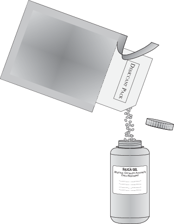
In extremely humid conditions (that exceed the specifications of the instrument) water vapor can be drawn into the LI-7550 and condense, which could result in damage to the electronics. Under normal operating conditions, the heat dissipated in the LI-7550 is sufficient to prevent condensation from forming on the electronics. However, if your site experiences condensing conditions on a daily basis, the desiccant pack kit (part number 7550-950) can help prevent condensation from forming inside the LI-7550. It includes a bottle (part number 6572-055) and desiccant (part number 9975-042).
To use the desiccant pack:
- Cut open the silver Mylar bag and open the internal bag.
- Pour the desiccant into the desiccant bottle and tighten the lid.
- Write the installation date on the bottle label.
- Place the desiccant bottle upright in the LI-7550, then close and latch the door.
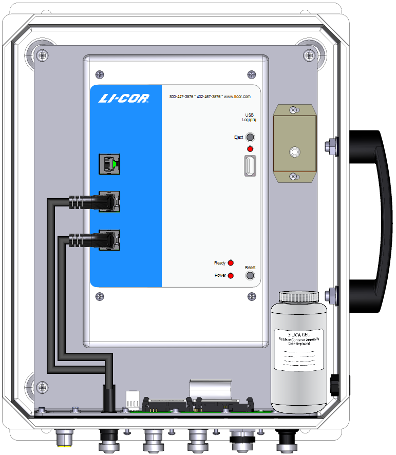
To help ensure that the desiccant does not become saturated, open the LI-7550 door only when needed. Opening the door allows humid air into the LI-7550, which depletes the desiccant.
The desiccant should be sufficient for one year of operation in most environments. Replace or recharge the desiccant after one year in normal conditions or more often in extremely humid conditions (e.g., if condensing conditions occur daily).
Adding a muffler to the air outlet
In some situations, the flow module may emit high-frequency noise through the exhaust port. This is especially noticeable when the blower motor is running close to the maximum motor drive, which can happen if there is a constriction in the flow tubing, either from a clogged filter or a kink in the tube. As a good practice, resolve any flow constrictions in the intake and tubing, as the flow constrictions lead to more power consumption and can cause other problems. To add a muffler to the outlet:
- Install a hose-barb on the flow module outlet.
- Cut about 15 cm of Tygon tubing from the flow module tube.
- Put the tubing and filter in series on the flow module outlet. Secure the tube with hose clamps.
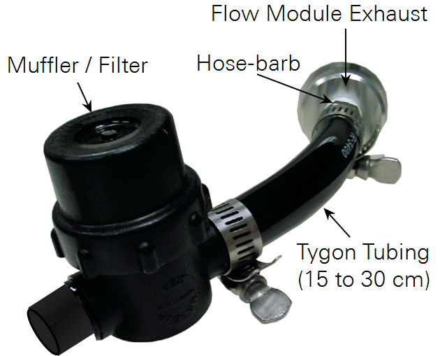
- Leave the filter in place to prevent insects from crawling into the flow module.
- More details are provided in a tech tip: licor.com/support/LI-7200RS/topics/ttp053-flow-module-noise.html
- Review a video of the muffler here: licor.com/support/LI-7200RS/videos/reduce-sound.html
Saving the configuration file
A copy of the configuration file can be saved for record keeping or to be loaded onto another instrument. To save the current configuration, click Config File > Save Configuration. Select the items to include in the file and click Continue. Select a directory and save the file. It will have a .l7x extension.
Exchanging sensor heads
Sensor heads are freely interchangeable between LI-7550 Analyzer Interface Units. Calibration information that is specific to the head is saved on the LI-7550. Therefore, you must enter calibration coefficients and current zero and span information for the attached sensor head. Calibration information can be entered directly into the software, or the calibration file can be loaded.
Manually entering calibration coefficients
- Attach the new sensor head to the LI-7550.
- Connect the instrument to a computer and establish communications.
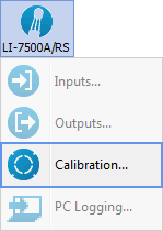
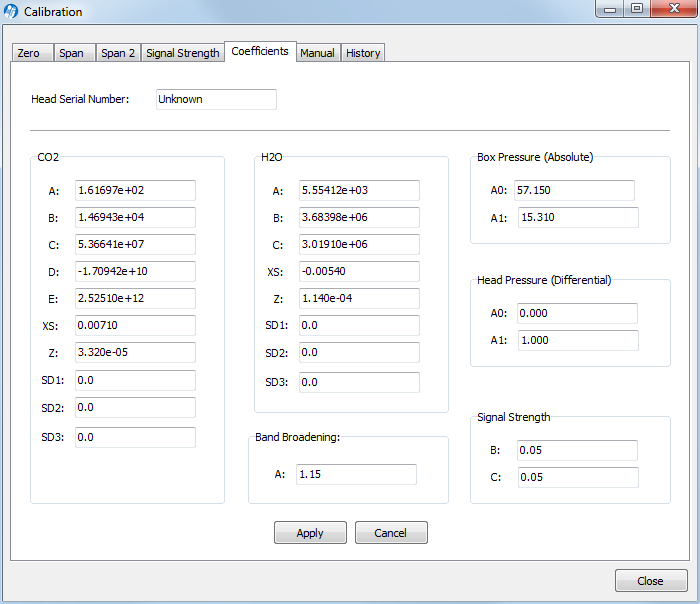
- Click LI-7500A/RS or LI-7200/RS > Calibration > Coefficients and enter the calibration coefficients from the Calibration Certificate.
- Zero and span the instrument.
Loading the calibration file
Acquire a calibration file for your instrument. You can get it from the LI-COR support site (licor.com/support) under calibration information, or you can save it from the LI-7550 (Config Files > Save Configuration). The file has a *.7x extension. To move a sensor head to another LI-7550:
- Attach the new sensor head to the LI-7550.
- Connect the instrument to a computer and establish communications.
- Select Config Files > Open Configuration. Choose the file saved earlier; the coefficients will automatically be loaded.
- Click LI-7500A/RS or LI-7200/RS > Calibration > Coefficients. You can leave the Box Pressure coefficients as the are.
- The Box Pressure coefficients saved in the old configuration file should not be used with the new Analyzer Interface Unit.
Moving the SmartFlux 2 System from one IRGA to another
The SmartFlux 2 System can be moved from one IRGA to another, but doing so requires that you clear data from the SmartFlux 2 System first. Before moving it, copy any files that you want to keep. Resetting the SmartFlux 2 System will clear all data from it. Then, click Diagnostics > Advanced > Factory Reset SmartFlux. Allow several minutes to pass before powering off the SmartFlux unit to ensure that is reset.