
Maintenance
The section describes maintenance procedures for the gas analyzer and components.
Cleaning the gas analyzer optical path
Important: Power off the gas analyzer (disable the power supply or disconnect the power cable) before conducting any maintenance that involves disassembly or disconnecting cables. Disassembling the instrument or detaching or attaching head cables while the instrument is powered on may damage the instrument or result in a loss of data.
The LI-7200/RS windows should be kept clean through regular maintenance. The analyzer is designed to make it easy to remove and clean the optics.
When operating without an intake filter, the cleaning frequency is dependent upon the air quality in the environment. In clean-air environments, the frequency of cleaning may be as low as several months. In environments or periods with high amounts of salts, pollen or dust, the frequency may be as high as every one to two weeks.
Important: The LI-7200RS detector is not affected by UV radiation when the optical path is open. The original LI-7200 detector, however, is affected by UV radiation. Exposure to direct sunlight temporarily reduces the sensitivity of the detector across all wavelengths, but it will not affect readings from the analyzer in most cases. If you are using an original LI-7200, cover the upper window with an opaque cloth or your hand when the optical path is open. If the detector is exposed to direct sunlight, it may take several weeks to recover. Let the instrument sit powered off for 3 to 4 days to shorten the recovery time.
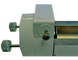
To open the optical bench, loosen the two knurled knobs on the top of the LI-7200/RS sensor head, and then pull the top of the sensor head out away from the optical bench (Figure 9‑1).
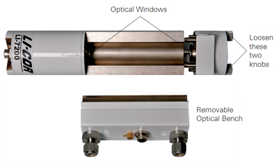
The sapphire windows are extremely durable and resistant to scratches. Clean them with a mild detergent or glass cleaner and a soft, lint-free cloth.
The optical bench has a PVC insert as the optical path. You can use mild soap and water, isopropyl alcohol, vinegar, or water to clean the optical path. Do not use acetone, ammonia, chlorine, or wire brushes to clean the path, as irreparable damage to the PVC insert can occur. Cleaning swabs in the spare parts kit (part number 610-05315) are to clean the optical path.
Reassemble the sensor head and perform a zero and span calibration as described in User calibration.
Replacing SmartFlux 2 System fuses
Power for the SmartFlux System and the pass-through power supply are protected by fuses. This section describes how to replace a blown fuse. Pass-through power flows through the SmartFlux System to pins on ports 1, 2 and 3 to power a connected sonic anemometer. To change the fuses, power off the SmartFlux System. Remove the power and data terminal strips. Remove the six screws on the side of the case and remove the case lid.
Important: Take care to avoid damaging nearby electronic components when removing fuses. Especially avoid prying on top of other electronic components.
3.0 Amp fuse for pass-through power
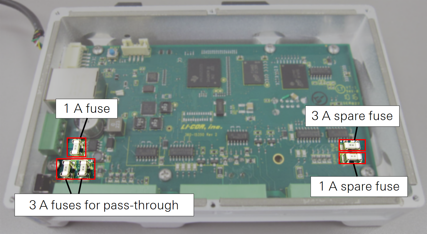
The SmartFlux System uses two 3.0 A fuses between the Power IN connector and the serial ports (see Figure 9‑2). One of these fuses is for the power wire to the anemometer or other connected device. The other 3.0 A fuse is for the power return wire and protects the system in case problems such as improper grounding cause a power surge.
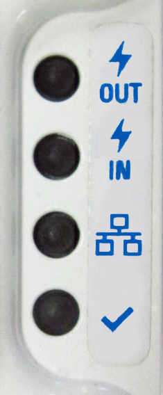
If the SmartFlux System boots up and has power, but the Power OUT LED does not light up, it is likely that one of the two 3.0 A fuses has failed.
- Measure both 3.0 A fuses with an ohmmeter. If one of them is an open circuit, replace it with the spare 3.0 A fuse.
- Remove the failed fuse and the spare 3.0 A fuse by gently prying under each fuse with a small flat-bladed screwdriver.
- Gently press the good (spare) fuse into the fuse holder. If both 3.0 A fuses are blown, you will need to order another 3.0 A fuse (part number 348-16020).
- Replace the lid and six screws on the SmartFlux 2 case.
Important: A blown 3.0 A fuse usually indicates a wiring problem between the SmartFlux System and the sonic anemometer or other connected device. Check for proper system grounding and remove possible causes of a short circuit in the power cable for the connected device. Also, while this fuse is rated at 3.0 A, keeping power use at 2.0 A or less will ensure a nearly unlimited lifetime for the fuse.
1.0 Amp fuse
If the Power OUT LED lights up, but the Power IN LED does not light up, it is likely that the 1.0 A fuse has failed (see Figure 9‑2).
- Measure the 1.0 A fuse with an ohmmeter. If it is an open circuit, replace it with the spare 1.0 A fuse (part number 348-13880).
- Remove the failed fuse and the spare 1.0 A fuse by gently prying under each fuse with a small flat-bladed screwdriver.
- Gently press the good (spare) fuse into the fuse holder.
- Replace the lid and six screws on the SmartFlux case.
Important: A blown 1.0 A fuse may indicate a problem with the SmartFlux 2 or 3 System. If the spare 1.0 A fuse also fails when installed, contact LI-COR support.
Replacing the LI-7550 fuses
Important: Power off the gas analyzer (disable the power supply or disconnect the power cable) before conducting any maintenance that involves disassembly or disconnecting cables. Disassembling the instrument or detaching or attaching head cables while the instrument is powered on may damage the instrument or result in a loss of data.
Early models of the LI-7550 have one fuse for the power supply. Later models have two fuses—one for the power supply and one for the accessory. To check a fuse, inspect it for evidence that it is burned and use an ohm meter to check the resistance. Resistance of <1 Ω (ohm) indicates that the fuse is OK.
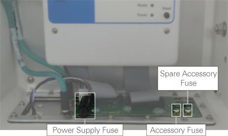
Power Supply Fuse
The power supply is protected by a 5 A 125/250V, 5 × 20 mm fast-blow fuse (part number 439-04214). If the battery or other power source fails to power the instrument, check to see if the fuse has blown.
The fuse is located in the lower left-hand corner, as shown in Figure 9‑3. Replacement fuses (part number 439-04214) are in the spares kit. Use a flat blade screwdriver or your thumb to push down on the fuse holder cap and turn counterclockwise to release the cap.
Accessory Fuse
The accessory uses a 2 A Nano2 SMF Fuse. There is one spare fuse included in the LI-7550. If the heated intake tube will not power on or continuously triggers an error, check the fuse and replace it if necessary.
Replacing the internal chemicals
Important: Power off the gas analyzer (disable the power supply or disconnect the power cable) before conducting any maintenance that involves disassembly or disconnecting cables. Disassembling the instrument or detaching or attaching head cables while the instrument is powered on may damage the instrument or result in a loss of data.
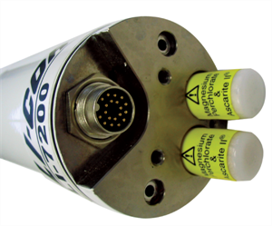
There are three small plastic bottles, each containing Ascarite II and magnesium perchlorate, in the upper and lower analyzer housings. The chemicals keep the source and detector housings free of CO2 and water vapor. They bottles should be recharged with fresh chemicals annually (or every 6 months in hot, humid climates). Replacement "charged" bottles are available from LI-COR in sets of three under part number 7200-950. If you want to recharge the bottles yourself, see Suppliers, for a list of suppliers of Ascarite II and magnesium perchlorate.
Note: Calibration shifts will occur if CO2 or H2O are not kept out of the analyzer housings.
To change the sensor head soda lime and desiccant bottles:
- Remove the chemical bottles.
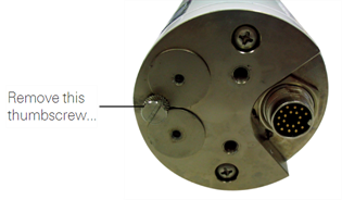
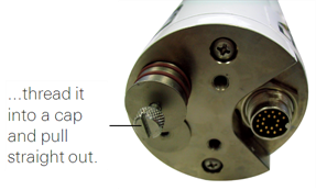
- The plastic bottles are in the lower analyzer housing in the sensor head. Remove the mounting bracket from the analyzer. Then remove the thumbscrew and thread it into a cap. Pull straight out to remove the plug.
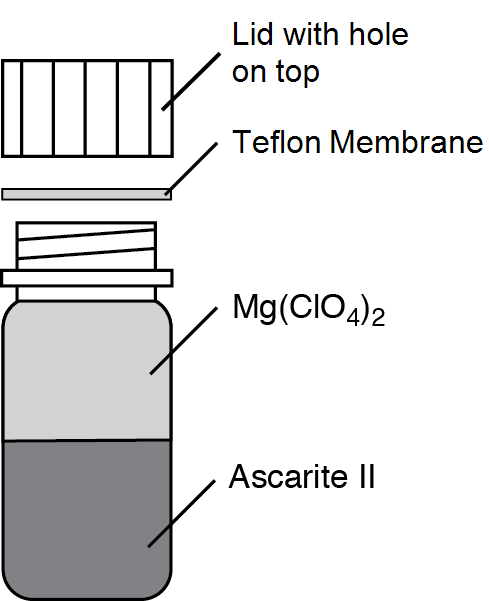
- Fill the bottles half full with Ascarite II first, followed by the magnesium perchlorate.
- Place the Teflon membrane in the lid to keep the chemicals from spilling into the detector housing.
- Insert the recharged bottles into the analyzer housing cap first. Replace the bottle covers.
- Use the retention screw to remove the bottle cover on the upper sensor head housing and insert the new, recharged bottle, cap first.
- Replace the cover retention screw and reattach the mounting bracket.
- After installing, allow at least 24 hours (with the instrument powered on) to scrub the housing; otherwise, the instrument may still drift.
- Set the CO2 and H2O zeros. Check the zero again, if possible, after one or two days.
Note: Read the technical note called "Using CO2 and H2O Scrubbers with LI-COR Gas Analyzers" for information about the interactions between scrub chemicals and the air.
See https://licor.app.boxenterprise.net/s/7i418s3uhd2uamoxfmjd.
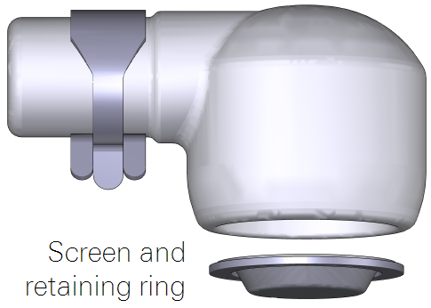
Cleaning the intake cap and screen
To clean the cap and screen, remove the intake cap assembly and back-flush it with compressed air or water. You can immerse the intake cap assembly in boiling water for a few minutes or soak it in an ultrasonic water bath. Usually, you should not have to remove the screen from the cap. If you do need to remove the screen:
- Insert a small screwdriver between the screen and intake cap.
- Use caution to avoid damaging the cap and deforming the screen.
- Carefully pull the screen out of the cap.
- Assembly is the reverse of removal. Be sure the screen is seated fully in the cap.
Cleaning the 2-micron intake filter
How do you know when to clean the filter? Dust will accumulate in the filter over time. The rate of dust accumulation will depend upon the amount of dust in the air and the particle size of dust. Therefore, it is difficult to predict exactly when the filter should be cleaned.
As dust builds up in the filter, the flow module will use more power to maintain the flow rate. So, the best indicator of the filter status is a change in the power required to run the flow module. When you install a new filter, record the Flow Drive (%), or log that variable with your data. Over time, compare the flow drive % with the initial value. The % will increase as the filter becomes clogged, indicating that the pump must work harder to move air through the filter.
Clean the filter before the Flow Drive (%) exceeds 90%.
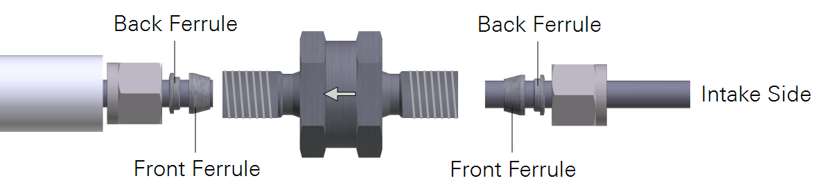
Cleaning: If possible, use an ultrasonic water bath, then back-flush the filter with compressed air and allow the filter to dry before reinstalling. Otherwise, immerse the filter in boiling water for a few minutes or soak it over night and then back-flush it with compressed air. As a good practice, clean the intake cap whenever you clean the filter. The ferrules do not need to be removed from the intake tubes when the filter is removed. They can be reused. See Installing the 2-micron particulate filter for more details.
Replacing the thermocouples
Important: Power off the gas analyzer (disable the power supply or disconnect the power cable) before conducting any maintenance that involves disassembly or disconnecting cables. Disassembling the instrument or detaching or attaching head cables while the instrument is powered on may damage the instrument or result in a loss of data.
There are fine wire temperature thermocouples located in the air inlet and outlet ports that measure the air temperature of incoming and outgoing air. Do not insert ¼” Bev-a-line or other small diameter tubing into the air IN or air OUT fittings, as you can break the fine-wire thermocouples present in each of the fittings. If a thermocouple does break, there are two replacement thermocouples in the spare parts kit (part number 9972-007S). Follow these steps to replace either air temperature thermocouple:
- Loosen the two knurled knobs on the top of the LI-7200RS sensor head and remove the optical path.
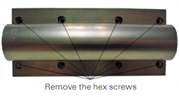
- Use a 7/64” hex key (part number 610-03745) to remove the eight hex screws on the back of the optical path.
- Separate the optical path from the inlet/outlet assembly, being careful not to strain the tubing that connects the two.
- Remove the small thermocouple circuit boards.
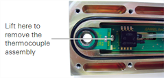
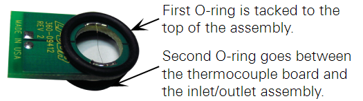
- The entire assembly, including the circuit board, is replaced as a unit (Figure 9‑7). There are two pins on the underside of the circuit board. Lift up on the end of the board to remove the thermocouple assembly and discard (Figure 9‑7). Make sure the two O-rings are present on the new board (one is tacked onto the thermocouple board; the other sits between the board and the opening), and insert the new assembly, making sure the two pins are inserted into the connector. Reassemble the optical bench.
- Reassemble the analyzer and perform a leak test (see Leak test) to ensure that the o-rings are seated properly.
Leak test
Follow these steps to perform the leak test:
- Attach the sensor head to the Analyzer Control Unit.
- Remove the tubing from the pressure inlet on the sensor head. It is attached to the small hose barb between the Air IN and Air OUT ports.
- Cut a short length (6” or so) of 1/16” I.D. Tygon tubing.
- There is a length of tubing in the spares kit (part number 222-09579). Attach this short length of tubing to the pressure inlet hose barb on the sensor head.
- Connect the instrument to your computer with the Ethernet cable.
- Open the LI-7200RS PC software and Connect to the instrument.
- Display Head Pressure (kPa)in the software dashboard.
- To change the variable displayed in the main data windows, click on the data value and select Head Pressure (kPa) from the list.
- Gently blow into the length of tubing connected to the pressure inlet.
- You should see a negative pressure displayed at Head Pressure in the dashboard. Alternatively, if you inhale, you should see a positive pressure. You can also push or pull air through the tubing using a syringe.
- Observe the Head Pressure reading over about 5 seconds.
- If the reading changes by an integer or more during this time (e.g. from -10.625 to -9.625), the sensor head may have a leak. Disassemble the sensor head optical bench and make sure the o-rings are seated properly. Repeat the leak test until the reading is stable within one integer over 5 seconds.
- Zero and span the instrument as described in User calibration.
Flow module maintenance
The flow module requires little routine maintenance.
Changing the fuse
The fuse in the flow module case can blow if power is applied with reverse polarity. Open the instrument case and unscrew the fuse cover to replace the fuse. The replacement fuse is a 5 A fast-blow, 125 V, 5x20 mm type, available from LI-COR under part number 439-04214.
Software updates
Go to licor.com/support/LI-7200RS/software.html for the latest versions. Update the all components in the system before deploying it.
We recommend running the most current software at all times, including both the embedded and interface software for the LI-7500A/RS or LI-7200/RS, EddyPro, and embedded software on the SmartFlux System. Check the installed version of the embedded analyzer software by clicking the Diagnostics tab at the top of the .
On the support web site, select your instrument, then select Software. Download both the Instrument (Embedded) Software and the Windows Interface Software.
Important: Read this before updating!
Firmware version 8.9 requires USB drives to be installed in the SmartFlux 2 System and the LI-7550 for dependable performance. Be sure to install USB drives in both the LI-7550 and the SmartFlux 2 System before installing the update. Also:
- Clear data from both USB drives prior to initiating the update. This ensures that there is adequate memory available to perform the update.
- Reapply the FluxSuite settings after the update is complete.
- Reapply data repository settings after the update is complete.
- To optimize performance of the LI-7550 with the SmartFlux 2 System, set RS-232 output to 0 Hz.
Embedded instrument software
To update the embedded instrument software:
- Make sure your gas analyzer sensor head is connected to the LI-7550 Analyzer Interface Unit. Power up the gas analyzer. Connect your computer to the system Ethernet switch (as shown) or to an open Ethernet port inside the LI-7550 using an Ethernet cable with standard RJ45 connectors.
- Important: There must be a USB drive in the LI-7550 USB port. For the best speed and performance, it's best to use a USB drive with no data on it.

- The Instrument (Embedded) Software is a zipped file named something similar to LI-7xxx_embedded-7.0. Unzip the files and save them.
- Double-click the file called update7x00.

- Click Browse... and select the instrument from the list. You may need to allow the application to pass through your computer's firewall.
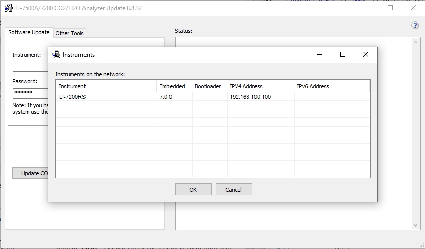
- Select the gas analyzer from the list and click Update Software.
- The update will take about 5 minutes.
- Important: Do not close the software, let your PC go to sleep, or power off the instrument during the update process. The software will notify you when the update is complete. If the update fails for any reason, repeat steps 2 and 3.
- If you are updating from embedded version 4.x.x or earlier, you must also run the FPGA update. To check if this update is necessary click the Check FPGA button. Note: Do not check the FPGA version until you update the system software.
- If the FPGA update is needed the Update FPGA button will become enabled in the application. The FPGA update takes approximately 10-12 minutes.
- Important: Do not close the software or reset the instrument while the update is taking place. The software will notify you once the FPGA programming is finished.
- After updating the software, check all your instrument configuration settings. The instrument should retain all settings through a software update, but in unusual circumstances, some settings may be lost.
Troubleshooting: Getting an update error? There must be a USB drive installed in the LI-7550 USB port before you can update. Also, if the drive is inserted for the first time, the instrument will take a few minutes to connect with the drive.
Windows interface software update
To update the Windows interface software for gas analyzers:
- The Windows interface software is an executable file named something similar to LI‑7x00_win-8.0. Double click to launch the installer.
-

- Follow the Windows Installation wizard to install the application.
SmartFlux 2 System software update
To update the software:
- Save the SmartFlux software update package to your computer.
- It is a collection of files in a zipped folder. Extract the contents of the file.
- Double click the file called update7x00.exe.
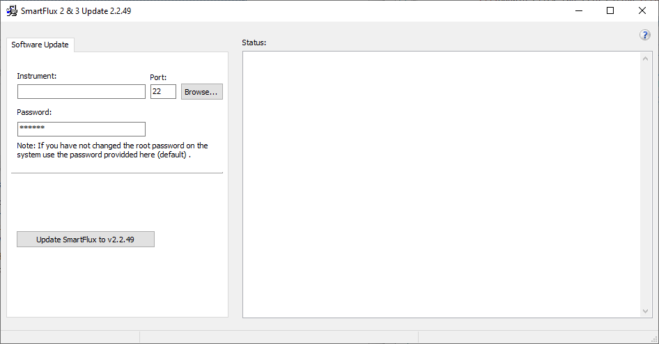
- Click Browse to view systems. You can also enter SmartFlux IP address or hostname as the Instrument.
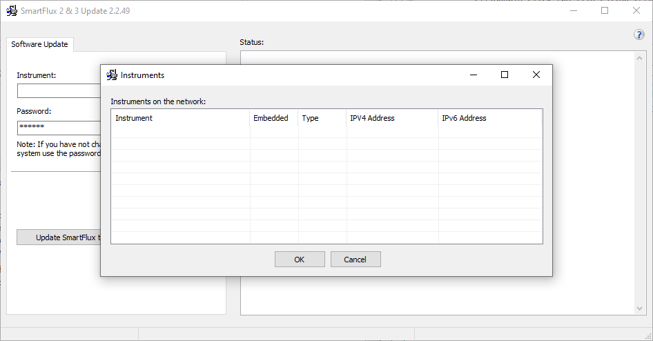
- You may need to allow the updater to pass through your computer firewall. Your computer firewall may prompt you if required. All SmartFlux 2 and 3 Systems connected to your network will be visible in the window.
- After selecting system or entering the IP address, click Update Firmware.
- The updater will load the new system files. This process takes about 30 seconds to a minute to complete the update. Do not power off the device while it is updating.