Sonic anemometer connection options
This section describes how to connect with some anemometers using the optional USB cable. It also describes additional wiring options for anemometers.
USB connections for configuration
You can connect a sonic anemometer to a computer to view the firmware version, settings, and troubleshooting.
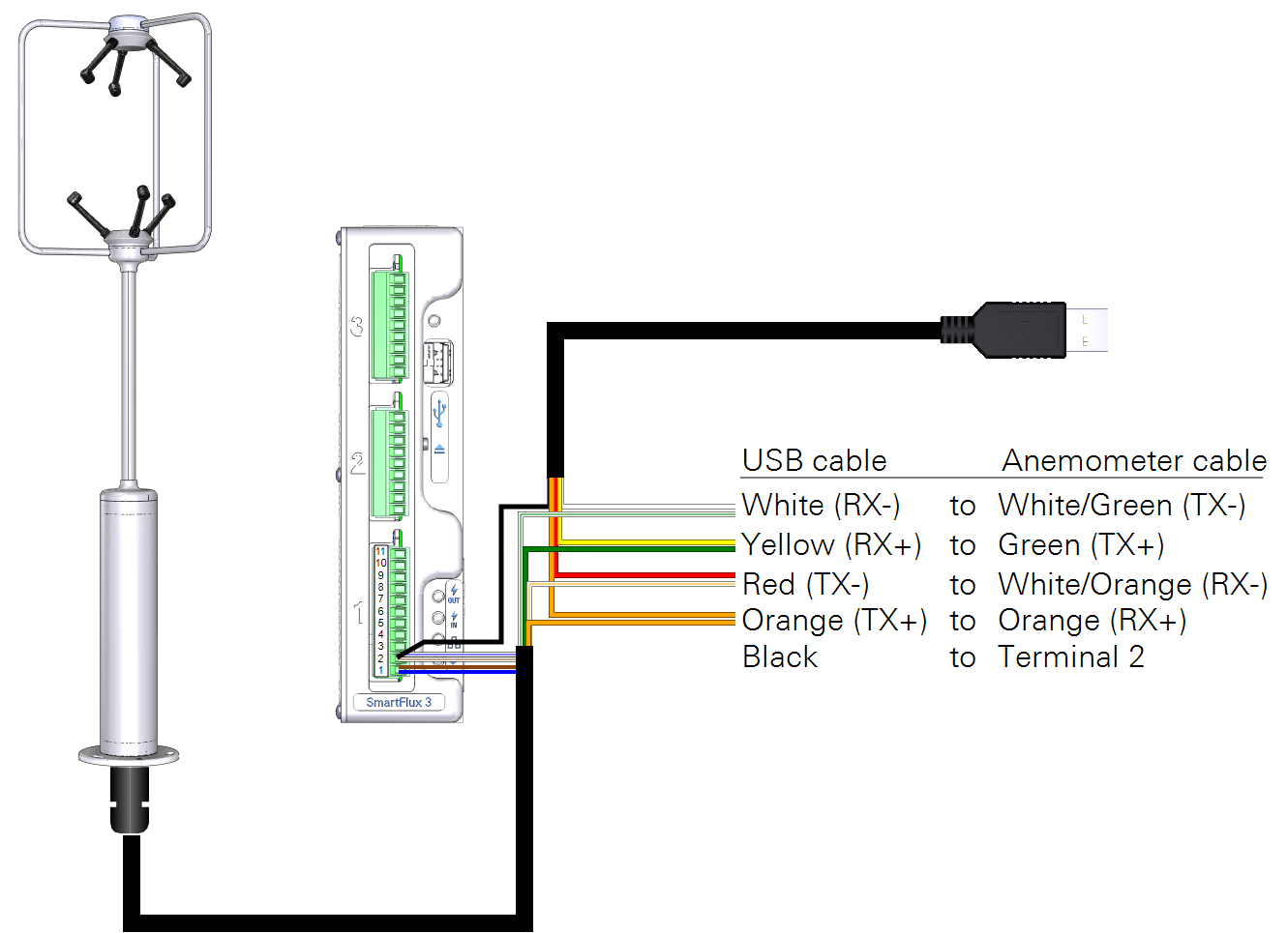
WindMaster/Pro
Important: Do not leave the USB cable connected to the anemometer during normal use. Failure to disconnect the cable may result in communication problems and data loss.
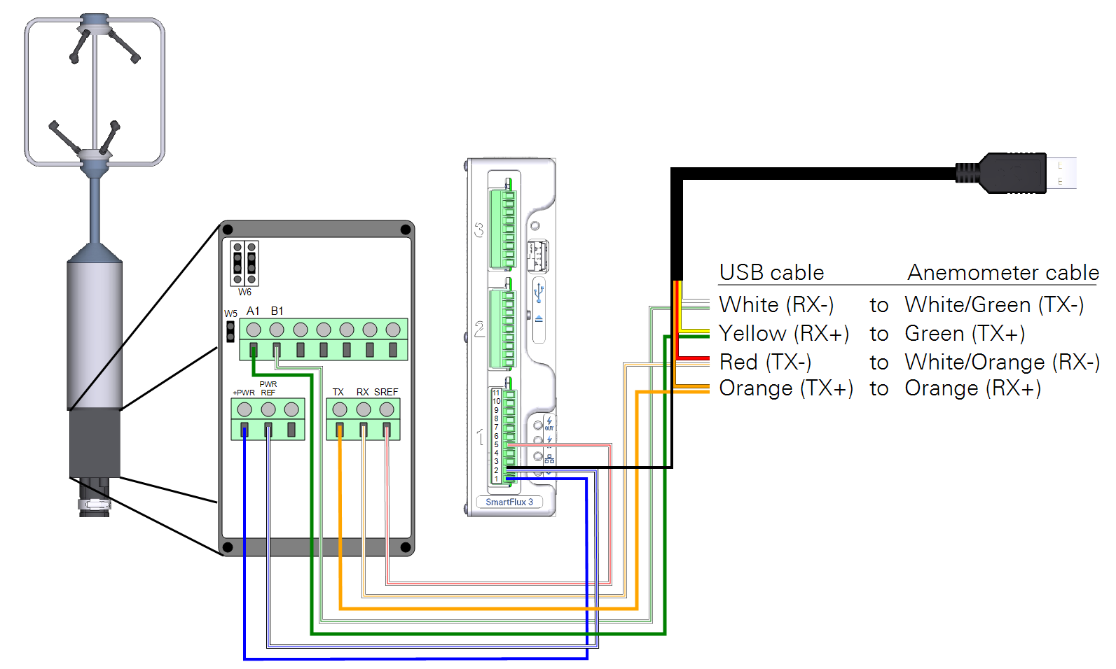
Use the suitable version of Wind software from Gill or a terminal program such as Tera Term. To connect the anemometer to a computer, attach bare leads of the USB-to-RS-422 adapter cable (392-16348) to bare leads on the anemometer cable. You can insert pairs into a single terminal in a terminal strip, twist them together, or connect them with wire nuts. To power the anemometer, connect the black lead from the USB-to-RS-422 adapter cable and the power leads from the anemometer cable to the Power Out terminals on the SmartFlux System.
The USB-to-RS-422 adapter cable requires a VCP driver, which you can download from www.ftdichip.com.
| USB Cable | connects to | Anemometer Cable |
|---|---|---|
| White (RX-) | connects to | White/Green (TX-) |
| Yellow (RX+) | connects to | Green (TX+) |
| Red (TX-) | connects to | White/Orange (RX-) |
| Orange (TX+) | connects to | Orange (RX+) |
| USB Cable | Anemometer Cable | connects to | SmartFlux |
|---|---|---|---|
| Black (GND) | White/Blue | connects to | Terminal 2 (Power -) |
| n/a | White/Brown | connects to | Terminal 2 (Power -) |
| n/a | Blue | connects to | Terminal 1 (Power +) |
| n/a | Brown | connects to | Terminal 1 (Power +) |
CSAT3B and CSAT3
Important: Do not leave the USB cable connected to the anemometer during normal use. Failure to disconnect the cable may result in communication problems and data loss.
Use the Device Configuration Utility from Campbell Scientific to configure the CSAT3 and CSAT3B.
- To connect the CSAT3B to a computer, use the cable from Campbell Scientific (30179).
- To connect the CSAT3 to a computer, attach bare leads of the USB-to-RS-232 cable (392-16347) to bare leads on the anemometer cable. You can insert pairs of wires into a single terminal in a terminal strip, twist them together, or connect them with wire nuts. The adapter cable requires a VCP driver, which you can download from www.ftdichip.com.
| USB Cable | connects to | Anemometer Cable |
|---|---|---|
| Brown (CTS) | connects to | White/Brown (RTS) |
| Green (RTS) | connects to | Brown (CTS) |
| Black (GND) | connects to | White/Orange White/Green (Signal Return) |
| Yellow (RX) | connects to | Green (TX) |
| Orange (TX) | connects to | Orange (RX) |
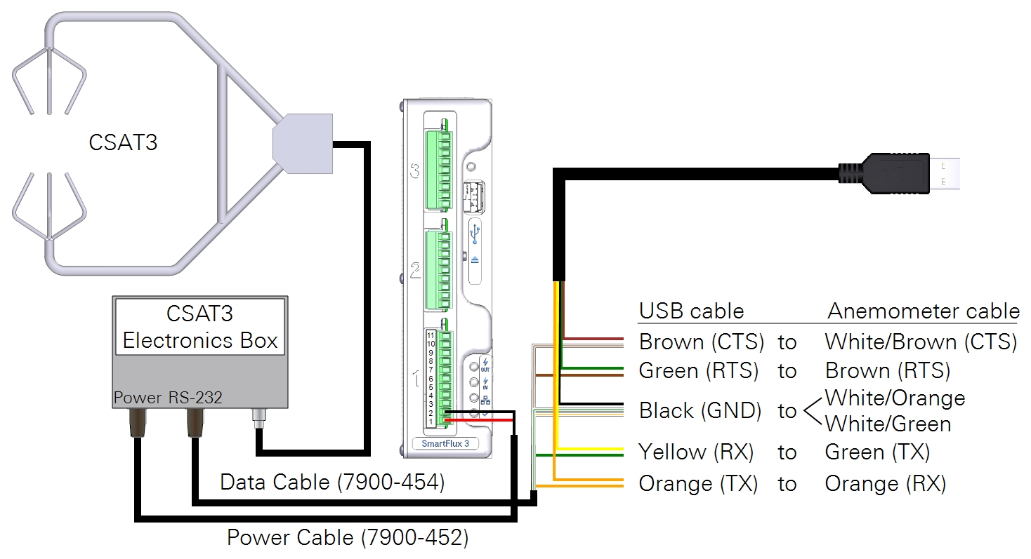
Power to the anemometer can be provide through the SmartFlux System. The black lead from the USB cable must be connected to ground, such as terminal 2 on the SmartFlux System.
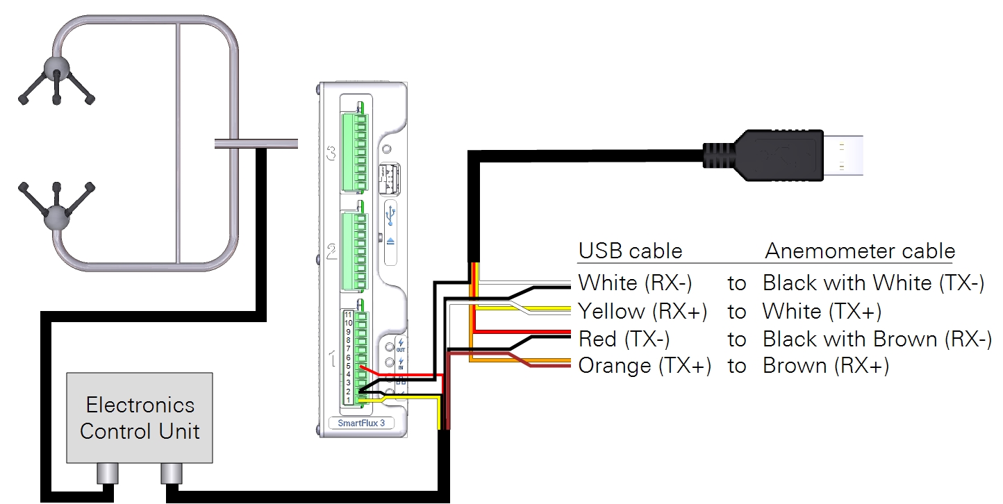
HS-50 or HS-100
Important: Do not leave the USB cable connected to the anemometer during normal use. Failure to disconnect the cable may result in communication problems and data loss.
Use the suitable version of Wind software from Gill or a terminal program such as Tera Term. To connect the HS-50 to a computer, attach the bare leads of the USB-to-RS-422 adapter cable (part number 392-16348) to bare leads on the anemometer cable. You can twist them together, connect them with wire nuts, or insert pairs into a single terminal in a terminal strip. Connect the black lead from the USB-to-RS-422 adapter cable and the power leads from the anemometer cable to the Power Out terminals on the SmartFlux System.
The USB-to-RS-422 adapter cable requires a VCP driver, which you can download from www.ftdichip.com.
| USB Cable | connects to | Anemometer Cable |
|---|---|---|
| White (RX-) | connects to | Black with white (TX-) |
| Yellow (RX+) | connects to | White (TX+) |
| Red (TX-) | connects to | Black with brown (RX-) |
| Orange (TX+) | connects to | Brown |
| USB Cable | Anemometer Cable | connects to | SmartFlux |
|---|---|---|---|
| n/a | Red | connects to | Terminal 5 (Signal Return) |
| Black | Black | connects to | Terminal 2 (Power -) |
| n/a | Yellow | connects to | Terminal 1 (Power +) |
You can also connect the HS-50 to your PC through the optional Gill Power and Communications Interface (PCI)—not pictured here. Consult the Gill HS-50 instruction manual for more on this method.
RM Young
You can connect the anemometer to a computer to view the firmware version and settings for troubleshooting.
Important: Do not leave the USB cable connected to the anemometer during normal use. Failure to disconnect the cable may result in communication problems and data loss.
Use a terminal program such as Tera Term to communicate with the anemometer. To connect the anemometer to a computer, attach bare leads of the USB-to-RS-422 adapter cable (392-16348) to bare leads on the anemometer cable. You can insert pairs into a single terminal in a terminal strip, twist them together, or connect them with wire nuts. To power the anemometer, connect the black lead from the USB-to-RS-422 adapter cable and the power leads from the anemometer cable to the Power Out terminals on the SmartFlux System.
The USB-to-RS-422 adapter cable requires a VCP driver, which you can download from www.ftdichip.com.
| USB Cable | connects to | Anemometer Cable |
|---|---|---|
| White (RX-) | connects to | White/Green (TX-) |
| Yellow (RX+) | connects to | Green (TX+) |
| Red (TX-) | connects to | White/Orange (RX-) |
| Orange (TX+) | connects to | Orange (RX+) |
| USB Cable | Anemometer Cable | connects to | SmartFlux |
|---|---|---|---|
| n/a | White/Red (REF) | connects to | Terminal 5 (Signal Reference) |
| Black (GND) | n/a | connects to | Terminal 2 (Power -) |
| n/a | White/Blue | connects to | Terminal 2 (Power -) |
| n/a | Blue | connects to | Terminal 1 (Power +) |
Additional serial connection options
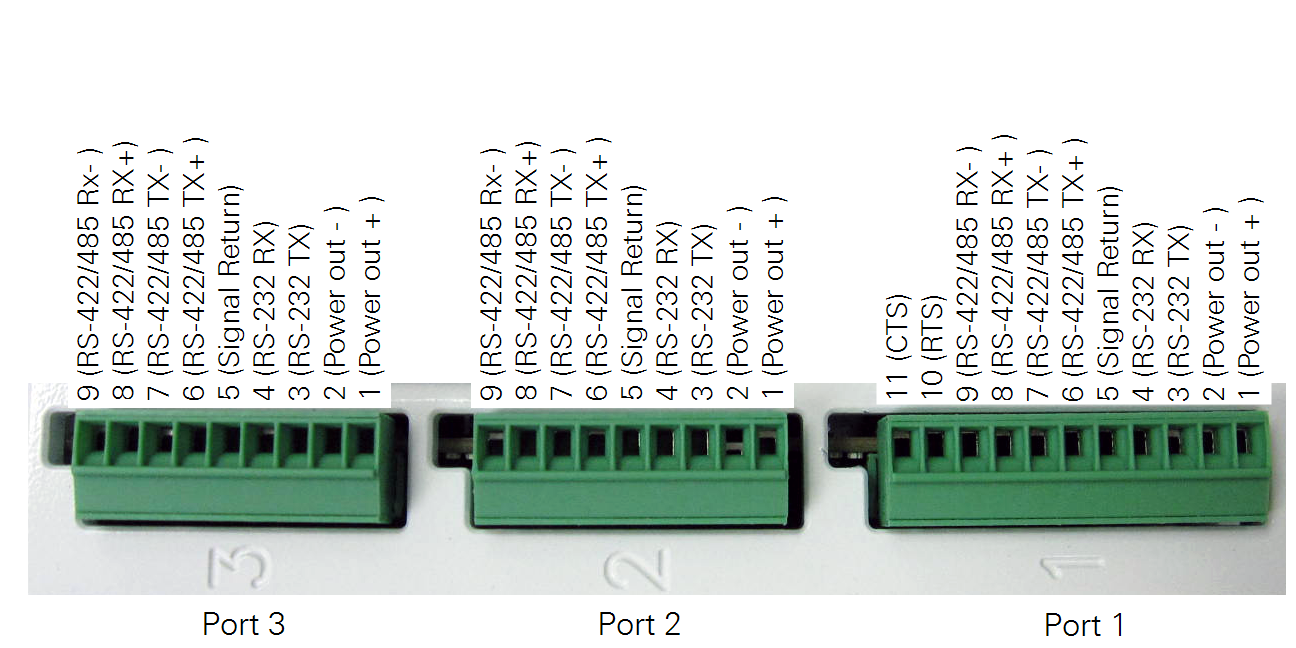
Here we describe more digital data cable options and details regarding wire colors, pin numbers, and part numbers. The SmartFlux 2 and 3 System features two 9-pin and one 11-pin UART (Universal Asynchronous Receiver/Transmitter) serial ports. The green terminal strips are made by Phoenix Contact.
| Serial Port | Terminal Strips | LI-COR Part # | Phoenix Part # |
|---|---|---|---|
| Port 1 | 11-pin 3.5 mm pitch | 331-15378 | Phoenix 1840450 |
| Ports 2 and 3 | 9-pin 3.5 mm pitch | 331-15376 | Phoenix 1840434 |
Serial port 1 has pins for RS-232 RTS (Request To Send) and CTS (Clear to Send) signals. Serial ports 2 and 3 do not have these pins. All 3 serial ports are equipped with RS-485 transceivers which allows them to be compatible with either RS-422 or RS-485 signaling. The serial ports support the Campbell Scientific CSAT3, CSAT3B, Gill WindMaster™, WindMaster™ Pro, R3-50, HS-50, HS-100, Metek Cage, Class-A, and RM Young 81000 series sonic anemometers. The current implementation of RS-485 is full duplex only.
The serial ports include power out pins to power the sonic anemometer. Using these power out pins also makes it easier to control the amount of voltage drop in the power wires to the sonic anemometer because no other currents flow in the anemometer power wires. This, in turn keeps the potential difference between the anemometer and SmartFlux 2 or 3 System small, which helps ensure trouble-free communication with the sonic anemometer.
3-Amp fuses limit the total power out current to the serial ports. It is best to keep the total current to 2 amps or less so that the fuses will never fail. The lifetime of the fuses will shorten as 3 amps is approached. For many—but not all—sonic anemometers, 2 amps will be more than adequate. If the power in LED for the SmartFlux 2 or 3 System is on, but the power out LED for the serial ports is not lit, then one of the fuses has failed. Two spare fuses are included inside the SmartFlux 2 or 3 System.
Important: Some sonic anemometers (CSAT3/A) have an upper voltage limit of 15 VDC. In this case, supplying an incoming 24 VDC to the SmartFlux 2 or 3 System could damage the sonic anemometer. The same voltage provided to the SmartFlux System is provided to a sonic anemometer that is connected to the Power Out terminals.
The following sections describe different methods that can be used to connect a sonic anemometer to the SmartFlux 2 or 3 System. There are multiple methods for some sonic anemometers and the best method might depend on what equipment you already own.
CSAT3
The CSAT3 can be connected to a SmartFlux 2 or 3 System with a LI-COR RS-232 cable and a CSAT3 Power cable.
Option 1
The 7900-454 cable will allow RS-232 signaling to function properly at 50 meters as long as the voltage drop in the power return wire is less than about 1 volt. If the CSAT3CBL3-L must be extended, use 18 or 20 gauge copper wire to easily meet this requirement. CSAT3 sonic anemometers should be wired to serial port 1, which supports the RTS and CTS signals of the CSAT3.
| SmartFlux 2 Port 1 | LI-COR 7900-454 RS-232 cable | CSAT3 10-Pin RS-232 Connector | CSAT3CBL3-L power cable | CSAT3 6-Pin Power connector |
|---|---|---|---|---|
| 11 (CTS) | White/Brown | H (RTS) | ||
| 10 (RTS) | Brown | G (CTS) | ||
| 9 (RX- ) | ||||
| 8 (RX+ ) | ||||
| 7 (TX- ) | ||||
| 6 (TX+ ) | ||||
| 5 (Signal Return) | White/Orange Green/Orange | E (Gnd) | ||
| 4 (RX) | Green | B (Tx) | ||
| 3 (TX) | Orange | C (Rx) | ||
| 2 (Power - ) | Black | B | ||
| 1 (Power + ) | Red | A |
See the Campbell CSAT3 Three Dimensional Sonic Anemometer Instruction Manual, (page 9, table 5-1, CSAT3 Power and page 10, table 5-6, CSAT3 RS-232 Output Pin Out).
Note: The mating connector for the CSAT3 RS-232 receptacle is Amphenol PT06E-12-10P(470). This style of connector is often referred to as a MIL-DTL-26482 series of connector.
Option 2
It is possible to connect a CSAT3 to a SmartFlux 2 or 3 System using only Campbell cables. Follow Campbell’s recommendation for maximum RS-232 cable length when using Campbell cables. See the Campbell CSAT3 Three Dimensional Sonic Anemometer Instruction Manual, (page 9, table 5-1, CSAT3 Power and page 10, table 5-6, CSAT3 RS-232 Output Pin Out).
| SmartFlux 2 Port 1 | CSAT3CBL2-L RS-232 Cable | CSAT3 10‑Pin RS-232 Connector | CSAT3CBL3-L Power Cable | CSAT3 6‑Pin Power Connector |
|---|---|---|---|---|
| 11 (CTS) | Black | H (RTS) | ||
| 10 (RTS) | Brown | G (CTS) | ||
| 9 (RX- ) | ||||
| 8 (RX+ ) | ||||
| 7 (TX- ) | ||||
| 6 (TX+ ) | ||||
| 5 (Signal Return) | Green | E (GND) | ||
| 4 (RX) | Red | B (Tx) | ||
| 3 (TX) | White | C (Rx) | ||
| 2 (Power - ) | Black | B | ||
| 1 (Power + ) | Red | A |
Note: The mating connector for the CSAT3 RS-232 receptacle is Amphenol PT06E-12-10P(470). This style of connector is often referred to as a MIL-DTL-26482 series of connector.
The CSAT3B has different cabling from the CSAT3. The Campbell-supplied cables should work well for connecting to a SmartFlux 2 or 3 System. There are two options for the power cable, CSAT3BCBL1 and CSAT3BCBL2. For this application, CSAT3BCBL2 will work best as it has heavier conductors and no unused wires. The RS-485 cable is CSAT3BCBL3. These are Campbell cable part numbers. These cables can be ordered in custom lengths from Campbell. These cables can also be supplied by LI-COR.
| SmartFLux 2 Port 1, 2, or 3 | CSAT3BCL3, 7900-464, CPI/RS-485 Signal Names | CSAT3BCL3, 7900-464, CPI/RS-485 cable | CPI/RS-485 Connector Pin Number | CSAT3BCBL1, CSAT3BCBL2, 7900-462 Power Cables | Power/SDM Connector Pin Number |
|---|---|---|---|---|---|
| 9 (RX- ) | TxB | Blue | 1 | ||
| 8 (RX+ ) | TxA | Blue/White | 6 | ||
| 7 (TX- ) | RxB | Brown/White | 2 | ||
| 6 (TX+ ) | RxA | Brown | 4 | ||
| 5 (Signal Return) | RGND | Green | 5 | ||
| 4 (RX) | |||||
| 3 (TX) | |||||
| 2 (Power - ) | Black | 2 | |||
| 1 (Power + ) | Red | 1 |
See the CSAT3B Three Dimensional Sonic Anemometer Instruction Manual (page 43, Table 7-3, CSAT3B Cable Wire Assignments).
HS-50
Important: At least 13 VDC must be supplied when using a 50 meter power cable because of voltage drops.
There are several ways to connect a Gill HS-50 to the SmartFlux 2 or 3 System. The method chosen will depend on the cables and equipment you might already own, and whether or not you are willing to cut or modify existing cables, and whether or not you would like to continue using existing cables directly with a PC. Another consideration is whether you have an HS-50 PCI (Power and Communications Interface).
Option 1
The first method is to connect directly to an HS-50 without a PCI using an adapter to the Gill 1086-M-043 Anemometer Cable. The Gill 1086-M-043 cable is intended to connect between an HS-50 Electronics enclosure and PCI, but it can be repurposed if the PCI is not needed. Creating an adapter allows the use of an existing 1086-M-043 Anemometer Cable without modifying the cable.
See the Gill HS-50 Horizontally Symmetrical Ultrasonic Research Anemometer User Manual (page 47, Section 13.2, Connector Pin Assignments).
An adapter can be made using a DB-15 cable or plug with pins for short distances (about 5 m). For long distances, use an Ethernet cable such as the Quabbin DataMax 5700 or 5750 or similar. The table here uses two pairs of wire for power.
| SmartFLux 2 Port 1, 2, or 3 | Quabbin DataMax Ethernet Cable | HS-50 Db-15 Pin number, plug with pins | HS-50 DB-15; Signal name | HS-50 Hirose 20-Position Connector pin number and signal name |
|---|---|---|---|---|
| 9 (RX- ) | White/Green | 9 | RS-485 Rx- | 3 (RS-485 Tx- ) |
| 8 (RX+ ) | Green | 2 | RS-485 Rx+ | 2 (RS-485 Tx+) |
| 7 (TX- ) | White/Orange | 10 | RS-485 Tx- | 5 (RS-485 Rx- ) |
| 6 (TX+ ) | Orange | 3 | RS-485 Tx+ | 4 (RS-485 Rx+) |
| 5 (Signal Return) | 4 | Signal GND | 13 (Digital 0V) | |
| 4 (RX) | ||||
| 3 (TX) | ||||
| 2 (Power - ) | White/Blue & White/Brown | 11 | Supply V- | 14 (Supply V- ) |
| 1 (Power + ) | Blue & Brown | 5 | Supply V+ | 6 (Supply V+) |
Option 2
If you already own or want to continue using a Gill PCI, and you want to use RS-232 signaling, an adapter can be built to accomplish this task. This will work well for short distances. It might be necessary to cycle power on the PCI if communications with the SmartFlux 2 or 3 system are lost in order to re-establish communication. For long distances, build the RS-422/485 adapter described in the next table. You will need to obtain a DB-9 cable or plug with pins to build this adapter. Plug this adapter between the PCI RS-232 port and the SmartFlux 2 or 3 System.
See the Gill HS-50 Horizontally Symmetrical Ultrasonic Research Anemometer User Manual (page 46, Section 13.2, Connector Pin Assignments).
Note: The Tx and Rx labels are not crossed in the wiring table.
| SmartFlux 2 Port 1, 2, or 3 | Optional, Colors using Ethernet cable | Gill DB-9 Signal Name | DB-9 with Pins |
|---|---|---|---|
| 9 (RX- ) | |||
| 8 (RX+ ) | |||
| 7 (TX- ) | |||
| 6 (TX+ ) | |||
| 5 (Signal Return) | White/Orange White/Green | Signal Ground | 5 |
| 4 (RX) | Green | RXD (Data from Anemometer to PC) | 2 |
| 3 (TX) | Orange | TXD (Data from PC to Anemometer) | 3 |
| 2 (Power - ) | |||
| 1 (Power + ) |
Option 3
Option 3 connects the HS-50 Electronics Enclosure to the SmartFlux 2 or 3 System using RS-422/485 and a modified Gill 1086-M-043, unmodified 1086-10-118 Anemometer Cable, or LI-COR 7900-445 HS-50 RS-485/Power cable (50 m), or 382-16158 HS-50 RS-485/Power Cable (5 meter).
This method will work well if the PCI is not needed, and there is no intent of ever connecting the HS-50 to a computer using the DB-15 connector on one end of the 1086-M-043 Anemometer Cable. In this case, the DB-15 connector can be cut off the cable, or a cable without the DB-15 connector can be ordered from Gill (part number 1086-10-118). The Gill 1086-10-118 cable can be ordered from LI-COR. Strip the insulation back from the conductors of the cable end about 5 mm to connect straight into the SmartFlux 2 or 3 connector. See page 40 of HS-50 Horizontally Symmetrical Ultrasonic Research Anemometer User Manual. The following table is set up using the same wire colors as shown for the Gill 1086-M-043 anemometer cable. It will be necessary to use an ohm meter to figure out the wiring because 6 of the wires in the 1086-M-043 cable are black. The black wires are not interchangeable. The connections must be made according the pin numbers shown for the SmartFlux 2 or 3 connector and the Hirose 20-way plug at the opposite end of the cable.
See the Gill HS-50 Horizontally Symmetrical Ultrasonic Research Anemometer User Manual, page 40, 1086-M-043 Anemometer Cable (Voltage Out).
Note: In this cable, Gill uses the standard convention of Tx+, Tx-, Rx+, and Rx-. The Tx and Rx labels are crossed in the cable diagram.
| SmartFlux 2 Port 1, 2, or 3 | Gill Wire Color | HS-50 DB-15; Signal name | HS-50 Hirose 20-Position Connector pin number and signal name |
|---|---|---|---|
| 9 (RX- ) | Black | RS-485 Rx- | 3 (RS-485 Tx- ) |
| 8 (RX+ ) | Green | RS-485 Rx+ | 2 (RS-485 Tx+) |
| 7 (TX- ) | White/Orange | RS-485 Tx- | 5 (RS-485 Rx- ) |
| 6 (TX+ ) | Orange | RS-485 Tx+ | 4 (RS-485 Rx+) |
| 5 (Signal Return) | Signal GND | 13 (Digital 0V) | |
| 4 (RX) | |||
| 3 (TX) | |||
| 2 (Power - ) | White/Blue & White/Brown | Supply V- | 14 (Supply V- ) |
| 1 (Power + ) | Blue & Brown | Supply V+ | 6 (Supply V+) |
Option 4
Option 4 connects the HS-50 Electronics Enclosure to SmartFlux 2 or 3 using RS-422/485 and unmodified Gill 1086-M-043 cable and dongle.
This method will work well if you own a PCI but want to bypass it without cutting your cable so it can be connected back to the PCI later. Use a quality Ethernet cable when making this dongle. The wire colors listed here are for using a Quabbin DataMax Ethernet cable.
Note: In this cable, Gill uses the standard convention of Tx+, Tx-, Rx+, and Rx-. The Tx and Rx labels are crossed in the cable diagram.
| SmartFlux 2 Port 1, 2, or 3 | Quabbin DataMax Ethernet Cable | HS-50 Db-15 Pin number | HS-50 DB-15; Signal name | HS-50 Hirose 20-Position Connector pin number and signal name |
|---|---|---|---|---|
| 9 (RX- ) | White/Green | 9 | RS-485 Rx- | 3 (RS-485 Tx- ) |
| 8 (RX+ ) | Green | 2 | RS-485 Rx+ | 2 (RS-485 Tx+) |
| 7 (TX- ) | White/Orange | 10 | RS-485 Tx- | 5 (RS-485 Rx- ) |
| 6 (TX+ ) | Orange | 3 | RS-485 Tx+ | 4 (RS-485 Rx+) |
| 5 (Signal Return) | Brown/White | 4 | Signal GND | 13 (Digital 0V) |
| 4 (RX) | ||||
| 3 (TX) | ||||
| 2 (Power - ) | White/Blue | 11 | Supply V- | 14 (Supply V- ) |
| 1 (Power + ) | Blue | 5 | Supply V+ | 6 (Supply V+) |