User calibration
The LI-7500DS’s measurement accuracy depends upon its calibration. There are two major components to the calibration: 1) determining the values of calibration coefficients, and 2) setting zero and span. During a factory calibration, both of these steps are performed. The values of the coefficients that are determined should be valid for several years. The zero and span adjustments are used to bring the LI-7500DS's actual response into line with its previously determined factory response, at least at two points.
Important: Check the zero and span at regular intervals; monthly at first, and then adjust the frequency according to the stability of the instrument; see How stable are zero and span?.
How stable are zero and span?
The analyzer's zero is primarily affected by temperature, and the state of the internal chemicals. The internal chemicals should be changed annually (see Replacing the internal chemicals). The zero's response to temperature is relatively small (typically 0.1 or 0.2 ppm per °C for CO2, or 0.01 mmol/mol/°C for H2O). Also, this drift is measured at the factory, and subsequently compensated for in software, so the effective zero drift should be quite small. Therefore, the zero should be quite stable over a several month period, but you might want to check it after an extreme temperature change (>30 °C).
The analyzer's span is affected by temperature, pressure, and the state of the internal chemicals.
- Temperature: A 10 °C change will typically change the H2O span by 1 to 2%. For CO2 at ambient concentrations, the span is very insensitive to temperature.
- Pressure: A large pressure change (40 kPa) will affect the CO2 and H2O spans by <1%, for ambient CO2 concentrations (>400 ppm) and high humidities (20 mmol/mol). So, diurnal pressure variations should not be a concern.
- Chemicals: Reduced internal chemical effectiveness will affect the span, but the effect on the zero will be much more pronounced. In summary, span stability is mostly a concern with H2O, when there are large temperature changes.
Note: Read the technical note called "Using CO2 and H2O Scrubbers with LI-COR Gas Analyzers" for information about the interactions between scrub chemicals and the air.
See https://licor.app.boxenterprise.net/s/7i418s3uhd2uamoxfmjd.
Checking the zero
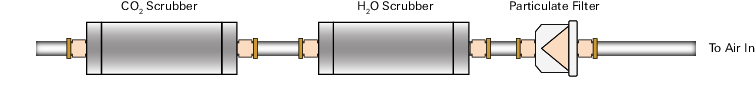
Flow a dry CO2-free air through the optical path and check the analyzer reading in the software dashboard. A suitable source of air for setting the zero can be generated with chemical scrubbers (such as soda lime for removing CO2 and magnesium perchlorate or Drierite® for removing water), or obtained from a cylinder of zero-grade gas.
When using chemical scrubbers, make sure that the chemicals are fresh and that air goes through the chemicals in the right order: Soda lime first, desiccant last (if the desiccant is Drierite®, allow time for the CO2 to "wash out" of it). Use a small pump to push the air through the gas analyzer.
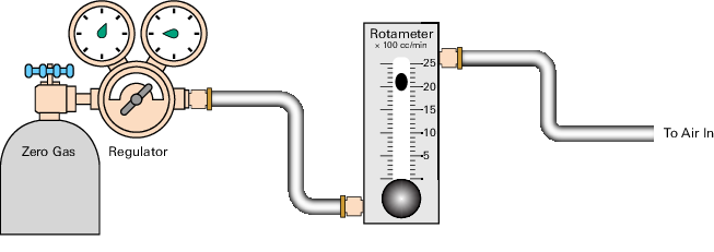
When using a cylinder, make sure that the air in the cylinder really is CO2-free since a typical cylinder of standard grade nitrogen might have as much as 20 ppm of CO2 in it. Compressed cylinders may be at pressures of several thousand pounds per square inch; before using them for calibration, they should be fitted with a regulator to reduce the pressure down to a range of around thirty pounds per square inch. Set the flow rate from 0.5 to 1.0 lpm.
Checking the span
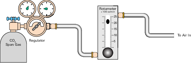
Check the CO2 span with a cylinder of CO2 in air at a concentration that is at the higher end of the range of concentrations which may be encountered during measurements. For example, a 500 to 1000 PPM cylinder of CO2 in air, which has been verified to be accurate to within at least 1% would be a suitable choice for many applications. Be cautious, as the stated value of the calibration cylinder may be significantly different from the actual gas concentration. Set the flow rate to 0.5 to 1.0 lpm. Check the analyzer reading in the software dashboard.
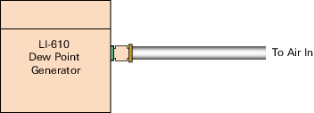
For the water vapor span, a convenient standard to use is a dew point generator such as the LI-610. To avoid condensation problems choose a dew point temperature that is about 3 to 5 °C below the ambient temperature. Also, since water vapor sorbs and desorbs from surfaces, allow plenty of time for the reading to stabilize. Set the flow rate from 0.5 to 1.0 lpm. Check the analyzer reading in the software dashboard.
Note: In general, if reliable calibration standards are not available or if there is not enough time to do the job properly, it is better to leave the zero and span settings alone than to rush through the procedure and make incorrect settings.
Span is a linear function of absorptance, so there is an offset term and a slope term. Both are determined at the factory, and when a (normal) span is set by the user, only the offset term changes. The slope term can be changed by performing a secondary span at a much different concentration than the previous (normal) span.
Step-by-step calibration instructions
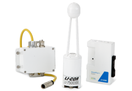
Both the LI-7500DS head and a DSI box are required to perform the calibration. To adjust the zero and span calibration:.
- Clean the LI-7500DS lenses using a soft, lint-free cloth and mild detergent if needed.
- Connect the cable from the calibration shroud to the connector on the DSI box. (Don't forget to reattach this cap when you're done.)
- Insert the calibration shroud into the analyzer.
- Insert the top of the fixture through the widest opening in the struts, near the bottom window. Slide it up, and then slide the bottom into place. It is important that the fixture is centered between the source and detector windows. View the CO2 Signal Strength while centering the fixture. If the CO2 Signal Strength value increases when the fixture is in place, it indicates that one or both of the windows are partially or totally obscured. Move the fixture back and forth until the CO2 Signal Strength value reads the same as before the fixture was inserted. The fixture is easy to center; if it looks centered, it probably is.
- Flow CO2-free air through the calibration accessory at a rate of about 0.5 to 1.0 LPM.
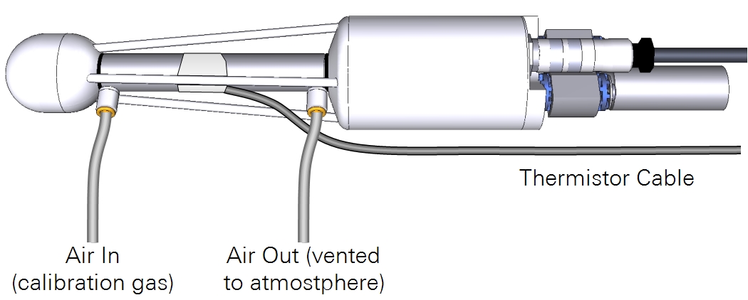
- Attach the zero gas to the calibration fixture at one of the ports shown in Figure 9‑4. The calibration accessory has quick connect fittings for use with standard 1/8” I.D. Bev-a-line (or other) tubing.
Zero CO2
Important: Always zero the instrument before spanning (don’t span, then zero).
- In the PC software, click LI-7500DS > Calibration .
- Verify that temperature reading looks OK by checking its value in the dashboard.
- Click on the Manual tab and view the value of Zco (CO2 Zero).
- Click the Zero tab.
- When the reading has stabilized in the dashboard, and the Gas Stability flag is green, click Zero CO2 to set the CO2 zero.
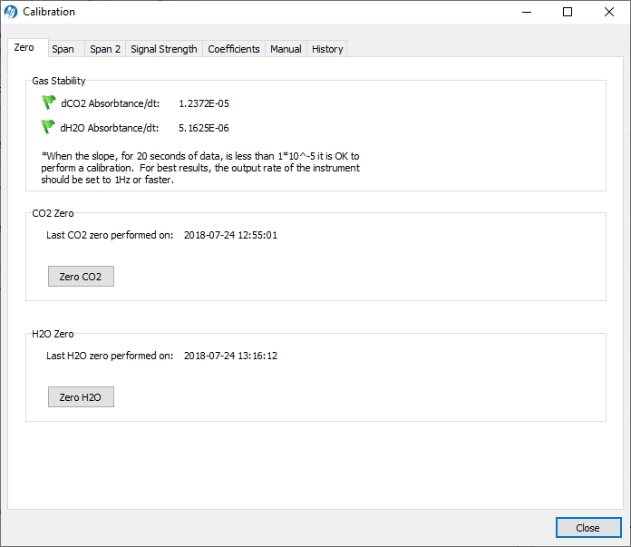
- After a brief delay, the displayed CO2 value should be fluctuating around zero. Check the value of Zco shown on the Manual tab. It should be near 1 (typically between 0.8 and 1.2). This value will steadily increase over time (2-3 months) as the internal chemicals lose effectiveness.
Zero H2O
Now is a good time to check or set the H2O zero, if you have been flowing dry, CO2-free air through the optical path.
- Click the Manual tab, and note the present value of Zwo (H2O Zero).
- Wait for the H2O reading to stabilize in the dashboard (3 or 4 minutes). The Gas Stability flag will turn from a red ‘X’ to a green flag when it is OK to perform the calibration.
- Click the Zero tab, and click Zero H2O. Note the new value of Zwo (typically between 0.8 and 1.2).
Span CO2
- Flow a CO2 span gas through the calibration tube at 0.5 to 1 liter/minute.
- Click on the Span tab and enter the mole fraction in the Span gas concentration field.
- When stable (1-2 minutes) click Span CO2.
- Click the Manual tab and check the new CO2 Span value Sc (typically between 0.8 and 1.2).
Span H2O
- To set the H2O span, flow air of known dew point through the calibration tube at about 0.5 to 1.0 LPM.
- To prevent condensation, use a dew point temperature several degrees below the ambient temperature.
- Click the Manual tab, and note the present value of the H2O Span value Sw.
- Go back to the Span tab and enter the span gas dew point temperature in the Dew point temperature field.
- Observe the H2O dew point in the dashboard and wait for it to stabilize.
- The Gas Stability flag will turn from a red ‘X’ to a green flag when it is OK to perform the calibration. This may take up to 15 or 20 minutes.
- When the reading has stabilized, click Span H2O.
- Click the Manual tab again and note the new H2O Span value Sw (typically between 0.8 and 1.2).
Considerations for setting the secondary span
If you find that after zeroing then spanning at one concentration, the instrument is not within specifications at a different concentration, a secondary span may be in order. The most common reason for doing this would be after a change in the chopper housing temperature set point. The two gas concentrations used for the span and secondary span should be as far apart as possible. For example, at the factory, this is typically done for CO2 using 200 ppm and 3000 ppm. At a minimum, the pair should be at least 500 ppm apart, and bracket your intended operating range (e.g. 300 ppm and 800 ppm). For H2O, you are constrained by the temperature of the air. You would normally choose a very low dewpoint, such as 5 °C, and something close to (just below) ambient. If the air temperature is 15 °C or less, you should probably avoid doing a secondary water vapor span.
Secondary CO2 span
- Zero the CO2 reading (see Zero CO2).
- Span the CO2 reading at a concentration below your normal operating range (something in the 200-300 ppm range, see Span CO2).
- Flow a CO2 concentration that is at or above your upper operating range (above 800 ppm, for example).
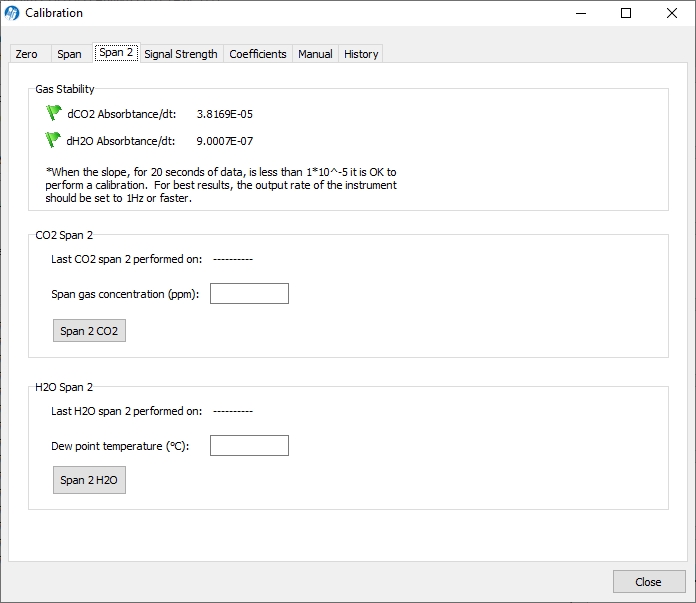
- Click on the Span 2 tab, and when stable, click Span 2 CO2.
Secondary H2O span
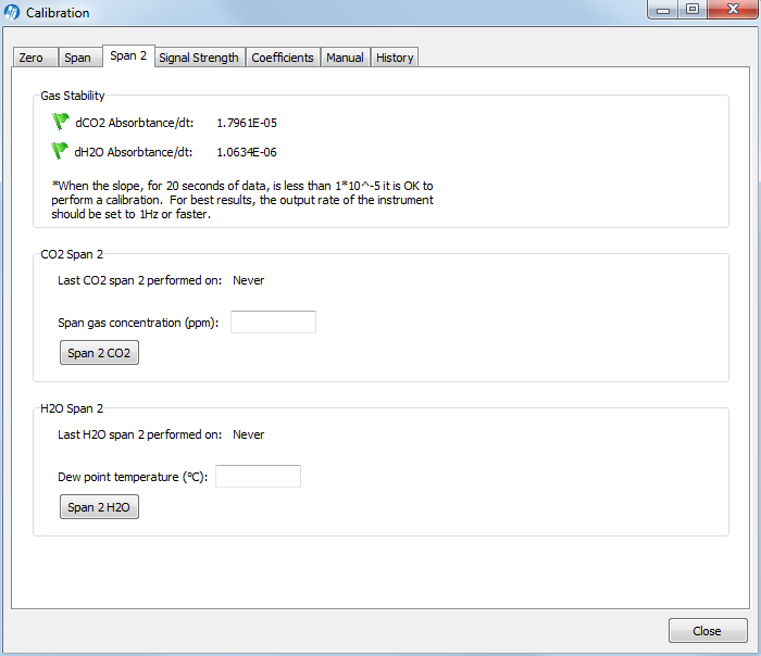
- Zero the H2O reading (see Zero H2O).
- Span the H2O reading at a dew point that is just below the ambient temperature (see Span H2O).
- Flow a very low dew point through the tubing.
- Click on the Span 2 tab, and when stable, click Span 2 H2O.
- It may take another 10 minutes or so to ensure equilibrium is reached when changing from one concentration to another, due to water present in the tubing, etc.
Re-attach the calibration thermistor cap when you are done.
Note: For both the CO2 and H2O secondary spans, you can reverse the concentrations if you wish. The normal span can be the high concentration, and the secondary the low concentration. Also, multiple secondary spans can follow a normal span. Simply make sure that the concentration difference between the normal span and any secondary span is large.
What actually happens
In the LI-7500DS the zero and span parameters are set in software. What actually happens when the zero is set is that the value of Zc0 (or Zw0 for water) is determined. For example, when CO2-free air is in the optical path of the analyzer, αc should be 0. From equation 11‑17,
9‑1

so
9‑2

Similarly,
9‑3

When the span is set, the value of Sc0 (or Sw0 for water) is determined. For example, if there is a known CO2 density r'c in the optical path and the measured absorptance is α’c, then from equations 11‑19 and 11‑8, we can write
9‑4

so
9‑5

We rewrite this in terms of a known mole fraction m’c instead of density.
9‑6

If we assume that the CO2 span gas is dry, then Pec = P, so

Similarly, for a known H2O mole fraction m'w and resulting measured absorptance α’w,

Whenever the CO2 span is set, the instrument saves two values that are used if and when a secondary CO2 span is performed. These values are

9‑9

When a secondary span for CO2 is performed at a mole fraction m’c with measured absorptance a’c, then the span slope term Sc1 is computed from
9‑10

A new offset term Sc0 is then computed using equation 9‑7, since the slope term Sc1 has changed. Similarly, for H2O, each time a normal water span is set, the instrument retains

9‑11

and when a secondary H2O span is performed at water mole fraction m’w with measured absorptance a’w, then the span slope term is computed from
9‑12

and a new offset term Sw0 is computed from equation 9‑8.