Field installation
This section describes how to install the instrument and its associated components on a tower or tripod in a typical eddy covariance application.
Mounting the gas analyzer and sonic anemometer
The sensor head should be mounted to a tripod or tower using the mounting kit (part number 7900-340) or a ¾ inch swivel mount. The head should be tilted at a 10 to 15° angle to ensure water does not pool on the lower lens.
Site considerations
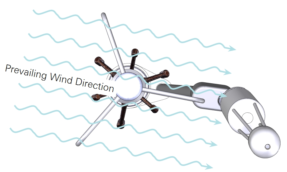
Plan your site with respect to the geographical area that is contributing to fluxes. Position the system downwind from that area. For mast-style anemometers, position the gas analyzer adjacent to a spar on the downwind side of the anemometer.
The sensor head can be positioned 10 to 20 cm from the anemometer in the horizontal direction. If mounted close to the canopy, the center of the analyzer and sonic anemometer should be at equal heights (within 20 cm). If mounted over 15 m up on a tall tower, horizontal and vertical sensor separation can be as large as 30 to 50 cm.
Installing the head mounting post
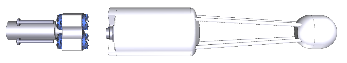
Begin by attaching the head mounting post to the analyzer head.
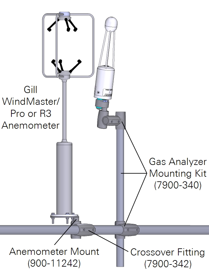
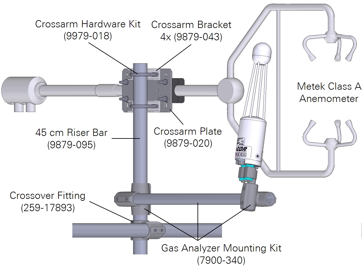
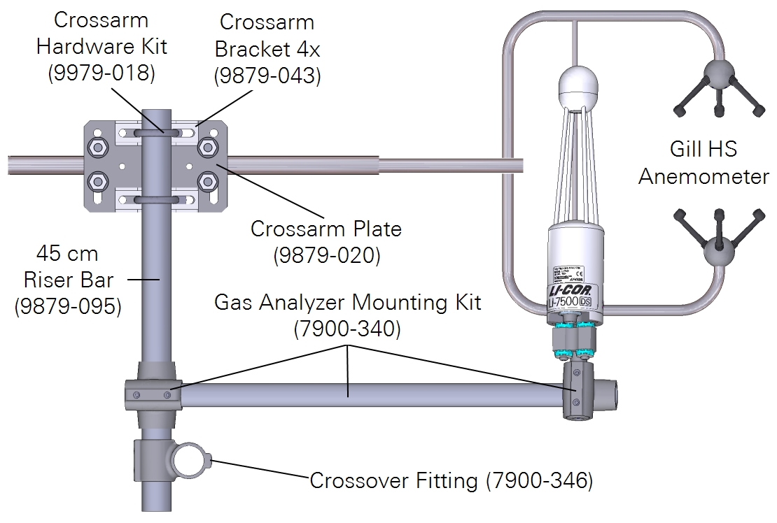
Mounting with mast-style anemometers
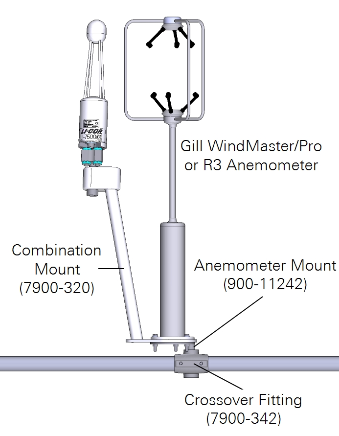
The head can be installed with mounting kit (part number 7900-340), which includes a cross-over fitting, riser bar, and swivel mount. The head should be tilted at a 10 to 15° angle to prevent water from pooling on the optics. Alternatively, it can be mounted with the combination mount (part number 7900-320) when using the WindMaster/Pro sonic anemometer.
Caution: The combination mount is designed for terrestrial applications. Environments where the device is subject to high- and low-frequency vibrations, shock, or impacts (e.g., mobile, shipboard, or buoy-mounted) may result in premature failure of the hardware. Use alternative mounting hardware or a secondary method to secure the components, especially if deployed over open water.
Set screws should be tightened to 22 N•m (16 ft•lbs). If no torque wrench is available, tighten each set screw until it contacts the pipe, then one more full revolution for aluminum pipe, or ¼ revolution for stainless steel. Use a 5/32" hex key for all the fittings except the ¾" × 1" crossover fitting (7900-342), which uses a 3/16" hex key.
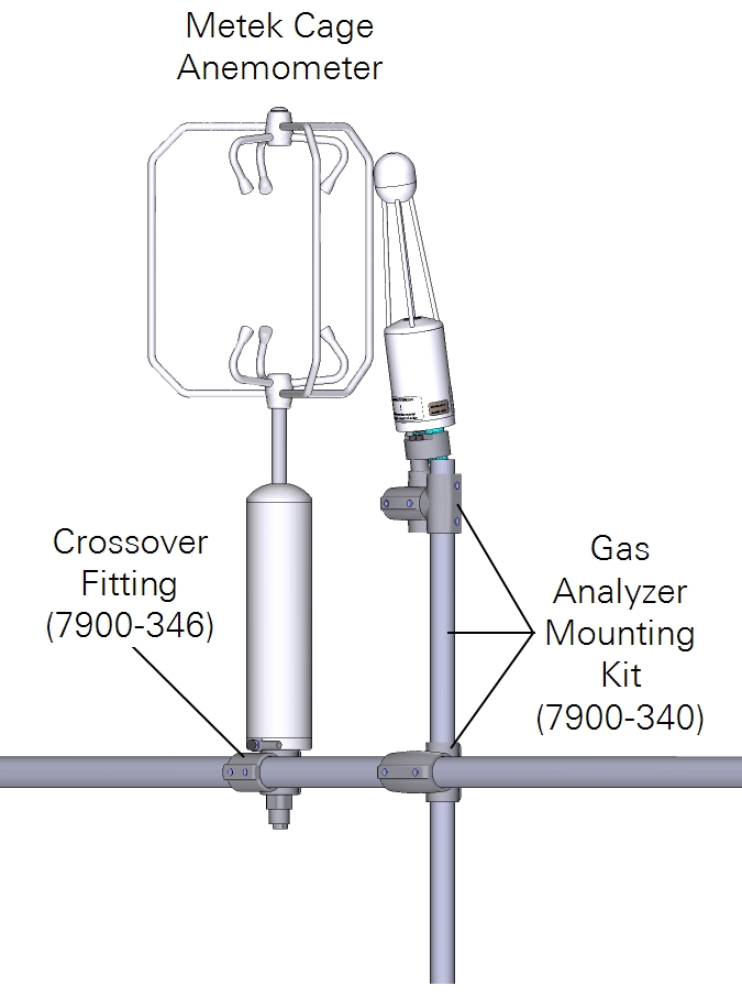
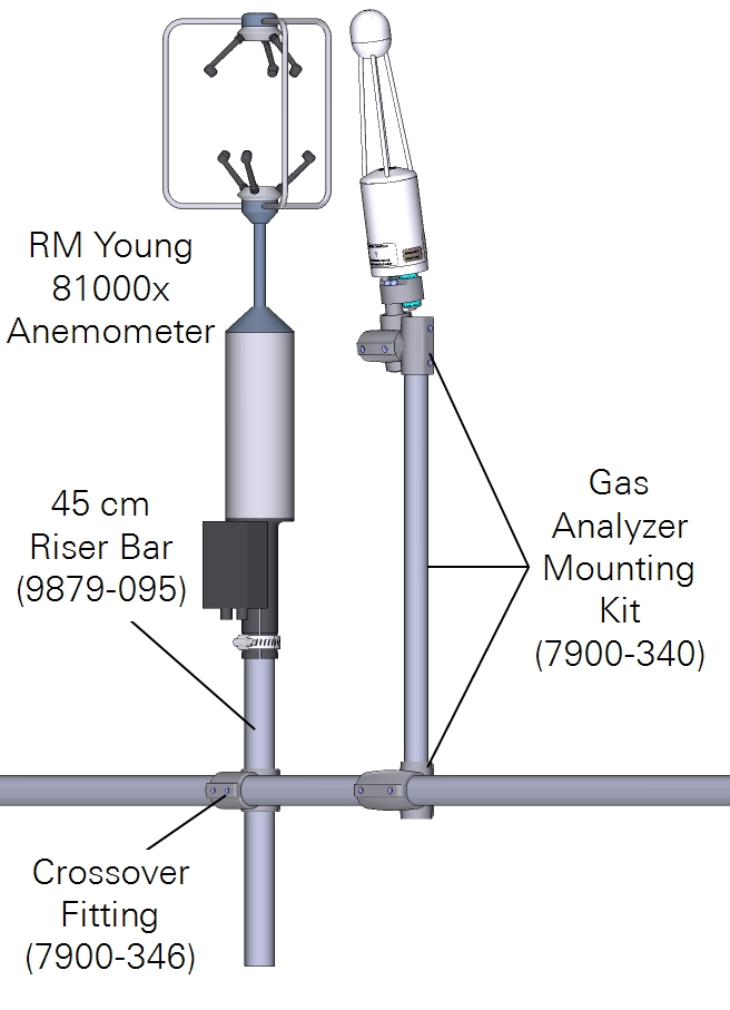
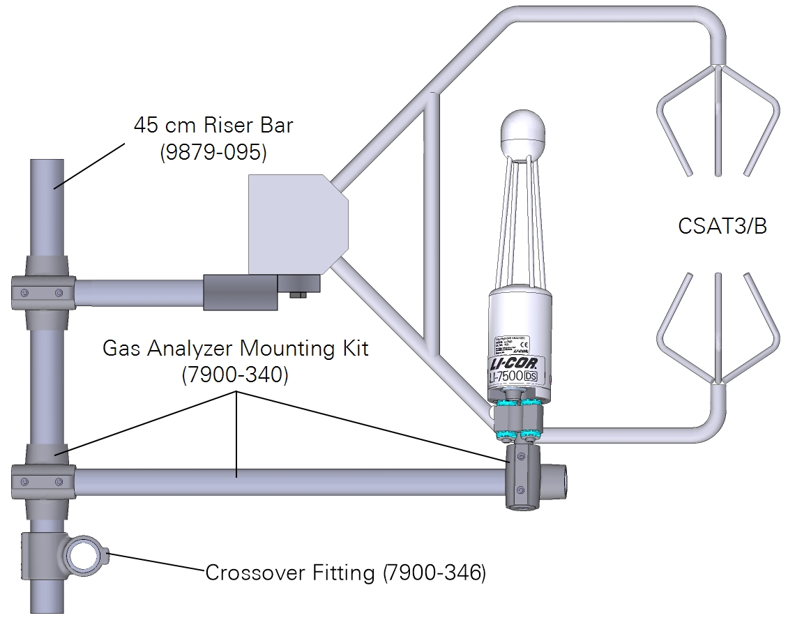
Mounting with c-clamp style anemometers
The head can be installed with mounting kit (part number 7900-340), which includes a cross-over fitting, riser bar, and swivel mount. The head should be tilted at a 10 to 15° angle to prevent water from pooling on the optics.
Set screws should be tightened to 22 N•m (16 ft•lbs). If no torque wrench is available, tighten each set screw until it contacts the pipe, then one more full revolution for aluminum pipe, or ¼ revolution for stainless steel. Use a 5/32" hex key for all the fittings except the ¾" × 1" crossover fitting (7900-342), which uses a 3/16" hex key.
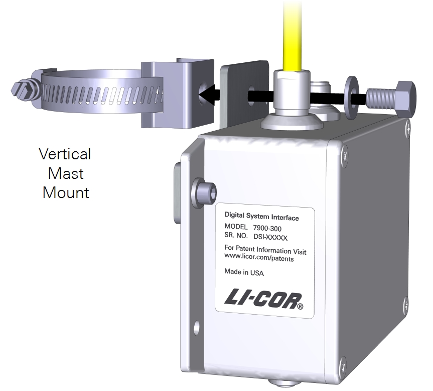
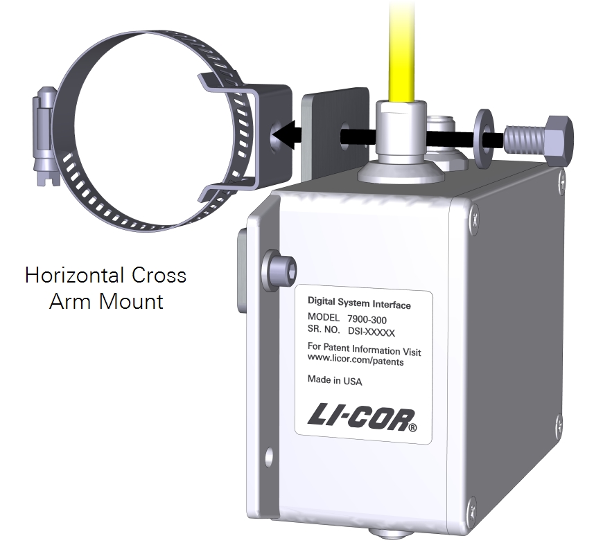
Mounting the DSI box
The DSI box mounts to a tripod or tower using the mounting bracket (see Figure 4‑6) and a band clamp (see Figure 4‑7). Do not block the pressure vent on the back of the box. Be sure that the analyzer head cable is not bearing the weight of the box.
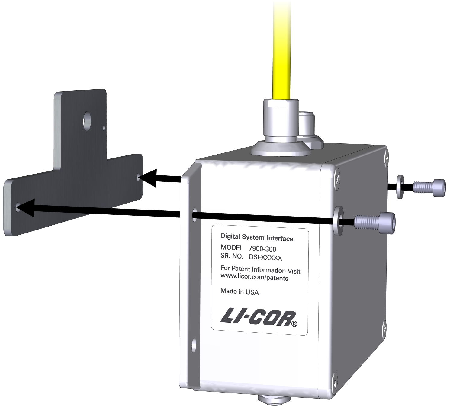
Orient the box vertically, with the gas analyzer head connector on the top and the power connector on the bottom.
Mounting the GPS antenna
Attach the GPS antenna to the mounting plate at the top of an enclosure with the included hex head bolt.
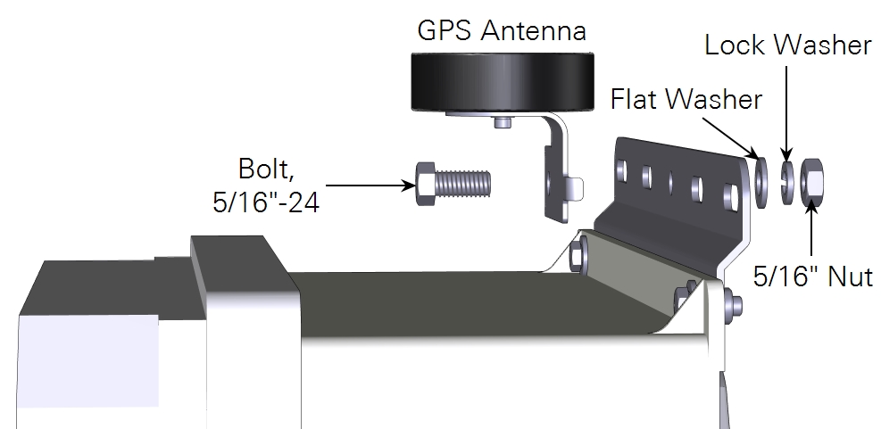
Important: Do not install the antenna inside of an enclosure. The GPS antenna will not receive satellite signals and the system will be unable to set the clock if it is installed in this manner. For best results, but sure that the antenna has a clear, unobstructed view of the sky.
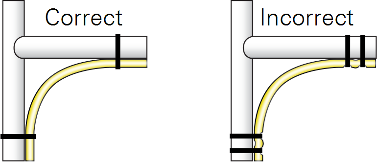
Securing cables
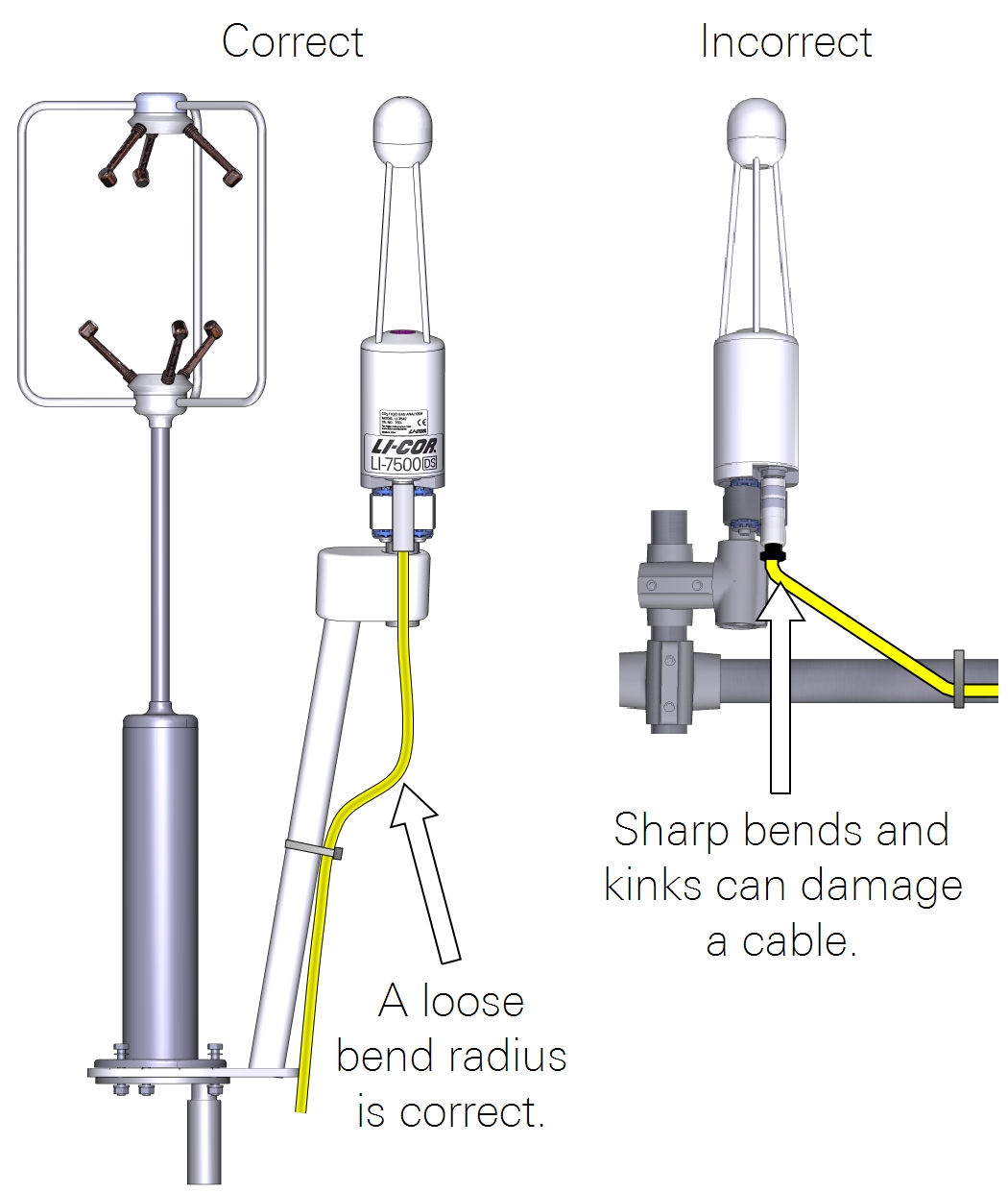
It is important that the head cable be connected properly to the sensor head. Follow these guidelines:
- There is a gasket in the head cable connector that should be compressed when the cable is connected. When tightening the connector, wiggle and push the connecter while tightening to compress the gasket.
- Provide a loose bend radius to allow the cable to absorb the energy of the bending over a greater portion of its length. Use a minimum bend radius of five times the cable diameter. For the head cable, this is a 1.75” (4.5 cm) minimum bend radius (or 3.5” (9 cm) minimum loop width).
- When tying cables with cable ties, leave the ties loose enough for the cables to slide freely under the tie. Never overtighten the tie to the point where the cable jacket becomes pinched.
Collect data on the setup
The final step of the site setup is to measure a number of parameters at the site. Each of the following should be recorded for later entry into the software. These values are used in flux calculations.
Site information
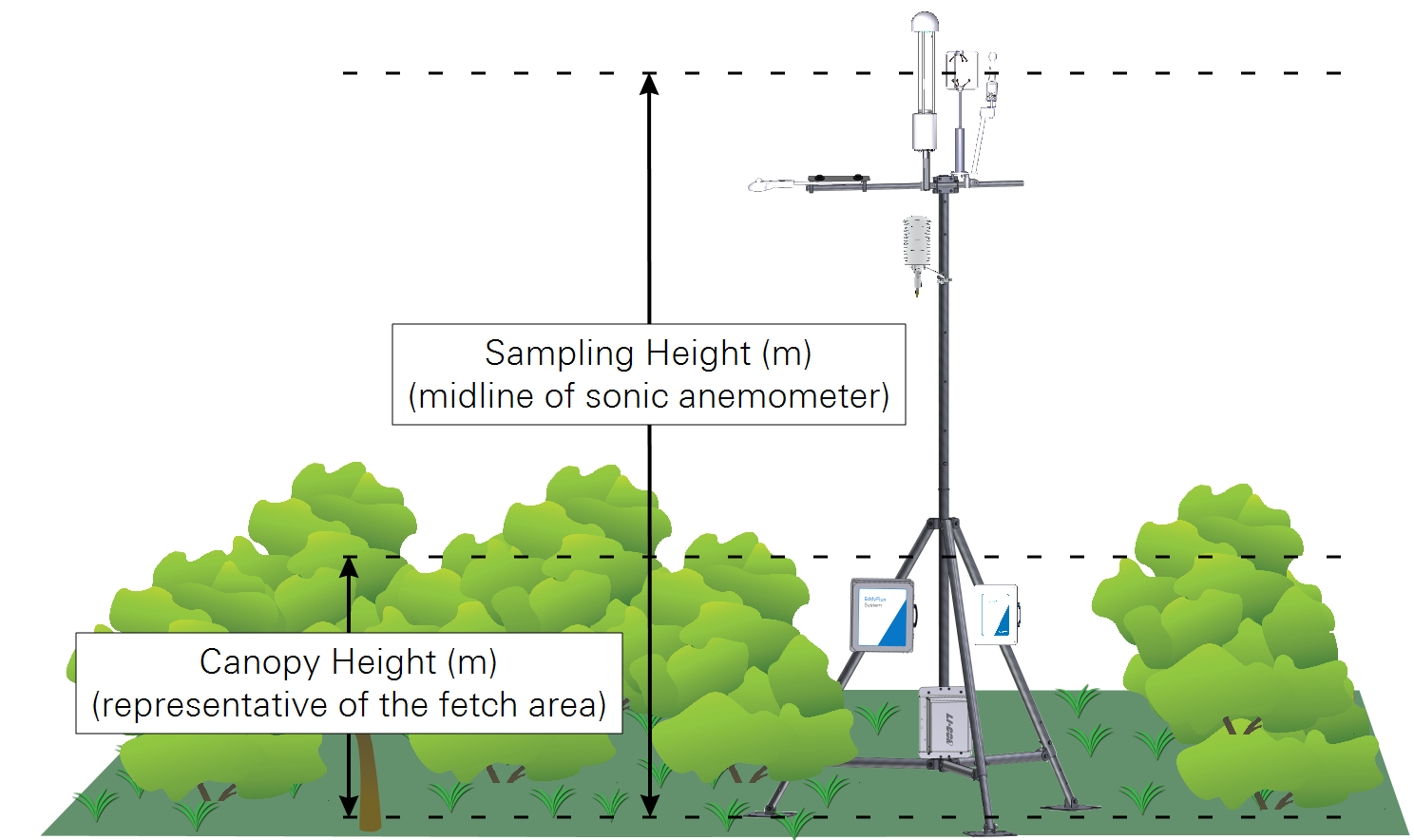
Measure both the canopy height and sampling height.
- Canopy Height (m): The distance between the ground and the top of the canopy. Since canopy height can vary from place to place, select a height that is representative of the canopy. If the canopy height changes during the sampling period, you may need update the height as the canopy grows.
- Sampling Height (m): The distance between the ground and the anemometer sample volume.
Sonic anemometer north offset
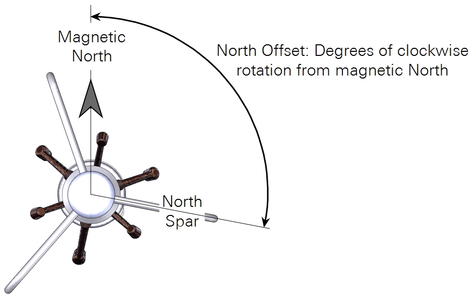
Determine the north offset of the anemometer.
- North Offset: Degrees of clock-wise rotation of the North Spar or Transducer Axis 1 from magnetic north.
Gas analyzer position
Measure the north, east, and vertical offsets.
- Northward Separation (cm): North (positive) or south (negative) distance between the anemometer and gas analyzer sample volumes.
- Eastward Separation (cm): East (positive) or west (negative) distance between the anemometer and gas analyzer sample volumes.
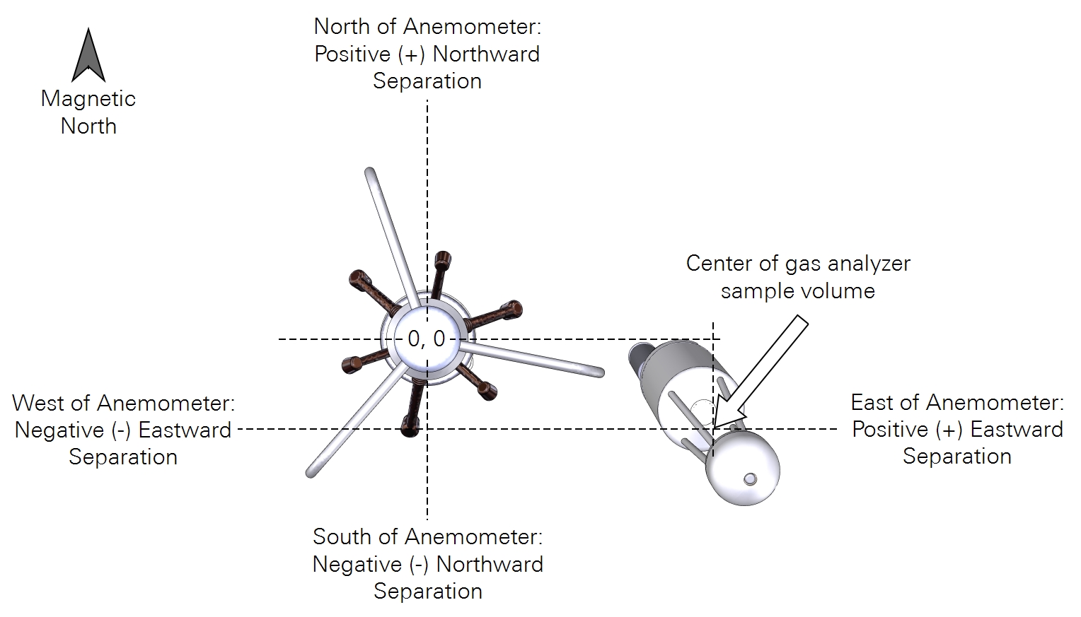
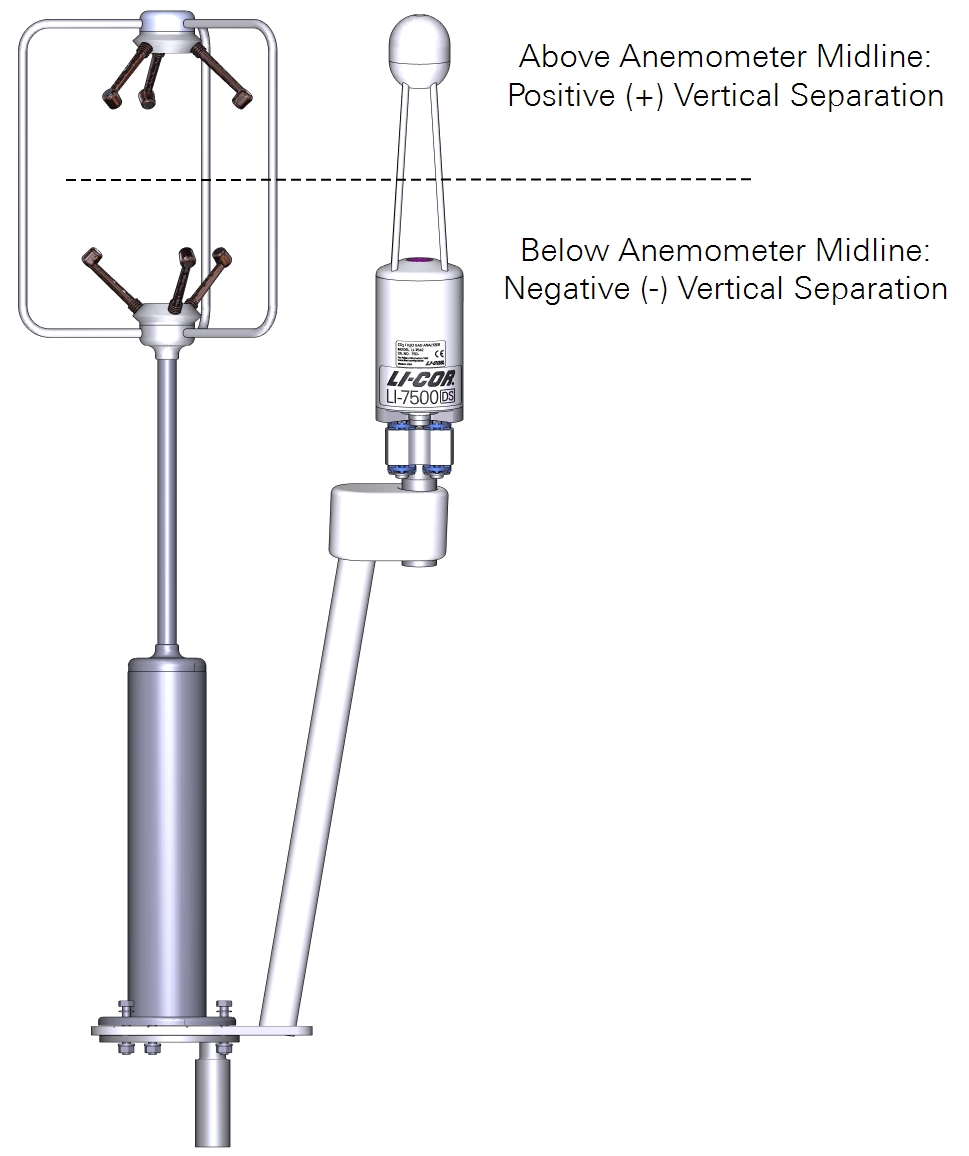
- Vertical Separation (cm): Distance between the anemometer midline and the gas analyzer sample midline. Positive value if the inlet is above the anemometer midline; negative value if the inlet is below the anemometer midline.