Troubleshooting
We address potential problems in this section.
Gas analyzer will not power on or repeatedly powers on and off
- Adequate power supply? The instrument requires between 11.5 and 30 VDC. During start up, 30 W is typically required, but it may be up to 37 W for a few seconds at cold temperatures. The power draw will decrease over a period of up to 10 minutes after start up until the internal temperatures have stabilized. Steady-state power draw is between 8 and 18 watts, depending upon the ambient temperature. Cold temperatures cause the instrument to draw more power.
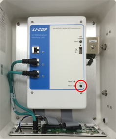
- If the LI-7550 Power LED turns on but the Ready LED does not, the power supply may be inadequate or the firmware has locked up. Check the power supply, restart the instrument, and update the firmware.
- If the LI-7550 Power LED cycles on and off repeatedly, the power supply is not sufficient to start up the instrument. Measure the voltage at the 4-pin connector inside the LI-7550 (rather than the voltage at the battery bank). The blue/black leads are positive (+), the brown/white leads are negative (-). If voltage at the connector is below 11.5 VDC, shorten the length of the power cable if possible, use a larger gauge cable, or boost the power supply voltage.
- Loose connection? Make sure the power cable connector is tight. Also check the cable for damage and the connections to the power supply.
- Blown fuse? Check the fuse, as described in Replacing LI-7550 Fuses. Note that a blown fuse usually indicates some other problem. If the fuse blows repeatedly, carefully check the wiring.
Problems with the SmartFlux 2 System
System powers on/off unpredictably or not powering the anemometer
- Check connections in the power supply and correct any faulty connections.
- Check connections on the SmartFlux System power wiring harness and tighten any loose fittings.
- Check the power wires. The positive wire should go to the Power IN (+) terminal and the negative wire should go to the Power IN (–) terminal on the SmartFlux 2 module.
- If the Power IN LED is lit, but Power OUT LED is not lit, then a 3A fuse inside the SmartFlux 2 module may have failed.
- Check the VIN value in the GHG windows interface software (under Diagnostics). Some sonic anemometers have an upper voltage limit of 15 VDC. In this case, supplying an incoming 24 VDC to the SmartFlux System could damage the sonic anemometer. The same voltage provided to the SmartFlux System will be provided to a sonic anemometer powered through the Power Out terminals.
System not visible on the network (cannot connect)
- Check the Ethernet Activity LED light on the SmartFlux 2 or 3 System. If it is blinking rapidly, this indicates the system is communicating over the network.
- Check the Ethernet cable and connections to the SmartFlux 2 or 3 system and in the rest of your EC system.
- Check the power supply connections and correct any faulty connections.
- Reboot the SmartFlux 2 or 3 System by pressing the reset button.
- Reboot the gas analyzer.
System not connected to the sonic anemometer
- If you have renamed the SmartFlux 2 or 3 System, does it have a valid name? The SmartFlux System name can only include upper and lower case letters (A to Z; a to z), numbers (0 to 9), the dash character (-), and the period (.). All other characters are invalid and will prevent the system from working as expected. One indicator of this is that the sonic anemometer status is displayed as disconnected in the gas analyzer software main window.
-
- Invalid names: Flux_Site_01 (invalid underscore _ characters); Micromet@TheSwamp (invalid @ character).
- Valid names: smart03-00901 (the default name).
- For manually configured anemometers, check to see that the sonic anemometer is set to the proper baud rate.
- Check the return signal LED lights next to the sonic anemometer data port. If they are flashing or solid, this indicates that the SmartFlux System is communicating with the sonic anemometer.
- Check the connections on the sonic data input plug wiring and tighten any loose fittings.
- Check the power supply to the anemometer.
- Reboot the SmartFlux System by clicking the Reboot button in the analyzer software (on the SmartFlux tab) or the reset button on the SmartFlux System.
USB flash drive not working properly
We recommend using a USB drive from LI-COR because it has been tested with the SmartFlux System. If you use a different USB drive, it should be industrial grade. If the USB LED blinks slowly (one time per second), this indicates an error. Try the following:
- Press the reset button on the SmartFlux System to re-boot the system.
- Unmount and re-mount the flash drive.
- Check to see if space remains on the USB drive. Remove files to free up some space.
Fluxes not being computed, are unreasonable, or raw data not time-aligned
- Check the time keeping settings for the system. Connect with the gas analyzer using the desktop software and verify that the PTP time keeping is On and set to Automatic for the gas analyzers.
- Be sure that the GPS antenna is installed outside of the enclosure and with a clear view of the sky. It must receive signals from GPS satellites in order to set the time.
- Check the results folder and look for the EddyPro log on the USB drive.
- Try processing data using EddyPro desktop.
Results are not identical to EddyPro desktop results
- Configuration settings are not the same. Review the configurations and ensure that they are identical.
- North Offset/Magnetic declination are set differently.
- Software versions not compatible. Although we attempt to test every possible scenario, there are cases that may lead to slight offsets in flux results. We fix bugs as they are identified. Ensure that you are running the most up-to-date version of EddyPro and the SmartFlux System embedded software. Contact LI-COR technical support (envsupport@licor.com) if you are unable to resolve the issue.
SmartFlux Status server errors
The SmartFlux status server communicates with the win-GHG appliction on a timed basis. Occassionally, you may just need to wait 15 seconds to a few minutes for the status to update. If the IRGA and a LI-7500RS or LI-7200RS are behind a cellular modem, you must check the Modem Connection box to instruct the application to retrieve status information. If the box is clear while the IRGA is behind a modem, the server will report that it is unable to contact the server.
Ethernet connection problems
Most Ethernet problems are related to firewalls or network settings.
Instrument not visible in software
- Firewall rules prohibiting the connection? Attempt to connect to the gas analyzer using the RS-232 connection. If you are able to connect as expected, the problem may be related to your computer firewall settings. Create an exception that allows the gas analyzer through the firewall. Refer to documentation provided with that software.
- Instrument network settings incompatible with computer or local area network settings? If the instrument IP address is set to Static, you probably will not be able to connect to the instrument over a network unless you change the instrument IP address to Dynamic (Obtain IP address automatically). Alternatively, connect to the instrument using the RS-232 serial connection.
RS-232 serial connection problems
When connecting with RS-232 serial, the Connect button in the PC software causes the program to set a break condition on the communication line, signaling the instrument to change to 9600 baud and send its current configuration. The PC then sends the desired configuration (update rate, baud rate, etc.) back to the instrument. Both instruments then change to the desired baud rate, and operations begin. When the Disconnect button is clicked, the PC signals to the instrument to change its RS-232 configuration back to what it was originally (or to that set up in the RS-232 panel).
"Port in use or does not exist"
- Correct COM port selected? This message indicates that the COM port setting on the Connect page is either incorrect, or else that COM port is already in use by some other program. If you are sure that the COM port is correct, and there is nothing else running, try rebooting the instrument.
"Not able to connect successfully"
- Click Connect again. Sometimes it takes a couple of attempts. If repeated attempts fail, then make sure the correct COM port is selected. Make sure the instrument is powered and running and see if the LED lights for about 5 seconds.
“Parse Error”
- Incompatible PC and instrument software? Update the PC application and embedded firmware on the instrument.
- Baud rate and update rate incompatible? In the Connect window, the Baud Rate menu is used to set the baud rate at which to communicate with the instrument. The rate of data transfer is also dependent upon the maximum rate available with your computer's serial port, and the update frequency to be used while the program communicates with the instrument.
- The Update Rate is the update frequency to be used while the PC software communicates with the instrument. Select from 0.1, 0.2, 0.5, 1, 2, 5, 10, or 20 Hz. At 9600 baud, the maximum update frequency is 2 Hz; at 19200 baud, 5 Hz; at 38400 baud, 10 Hz; at 57600 baud, 15 Hz; and at 115200 baud, 20 Hz. Use a faster Baud Rate and/or a slower Update Rate to resolve this problem.
Instrument software is unresponsive
- Incompatible PC and instrument software? Make sure that your PC software and instrument embedded software are compatible. Yellow indicators in the Connect dialog box are displayed when the instrument (embedded) software version is incompatible with the PC software. Green indicators are displayed when instrument and PC software are compatible.
- Reboot needed? The instrument can be rebooted using the Reset button on the LI-7550 control panel. Pressing the Reset button restarts the boot process; if connected via Ethernet, the instrument will attempt to reconnect to the PC software. If connected via RS-232, you may need to restart the PC software and reconnect manually.
Issues with gas analyzer measurements
Bad temperature readings
Temperature sensor connected? Be sure that the sensor is connected to the LI-7550.
Bad pressure readings
- Pressure source set incorrectly? You can select the source of pressure measurements, as described in Inputs. If the source is Measured, the readings come from the pressure sensor inside the LI-7550. If the source is Auxiliary Input 2 , then the pressure is from an external sensor that you have connected. This signal is modified according to the Auxiliary Coefficients that appear on that same page. If the source is User-Entered, then whatever you enter manually in the text box is used for the value.
- Instrument pressure doesn't match your barometer? The pressure sensor in the LI-7550 is good to about 0.1%. For operating purposes, it doesn't need to be very good (see A note about pressure and temperature). When setting the span(s) of the instrument, however, it is more important.
Bad CO2 or H2O readings
- Signal strength OK? Under the Diagnostics page, check the values of Signal Strength. Even if the signal strength looks acceptable, you may need to clean the optical windows.
- Are the diagnostic flags (PLL, etc.) OK? Under Diagnostics, check the diagnostics. See Diagnostics for more information.
- Zero and Span OK? Go to the Calibration page and make sure the current values of zero and span are near 1.
- Calibration coefficients correct? Make sure all of the coefficients on LI-7500A/RS > Calibration > Coefficients match the calibration sheet for the head. You can get the calibration certificate from the LI-COR web site. The Band Broadening coefficient should be 1.15.
Absorptances make sense, densities don't
If the absorptance value seems correct (rough rule of thumb: absorptance = 0 when density = 0, CO2 absorptance is about 0.1 with a mole fraction of about 400 ppm, and H2O absorptance is about 0.1 with a mole fraction of about 20 mmol/mol), but the displayed values of density or mole fraction are obviously bad, then the problem is in one of the following: calibration coefficients, span parameter, pressure value, and the band broadening value (CO2 only).
Readings very noisy
The variability in absorptance values should be low, with only the 4th decimal place changing once in a while. If density or mole fraction is still noisy, watch the temperature and pressure values to see if they are the source of the noise (or change to a hand entered, constant value to try this). Check the calibration coefficients and band broadening value (if the problem is with CO2) to make sure they are correct.