Configuring the LI-7700
Basic setup
The LI-7700 Windows software is used to configure the instrument. Go to licor.com/support/LI-7700/software.html for the latest version and install it on your computer. Download both embedded firmware and interface software. We recommend using the latest software for the best performance.
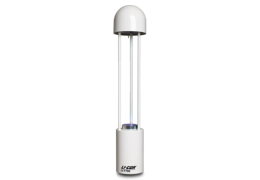
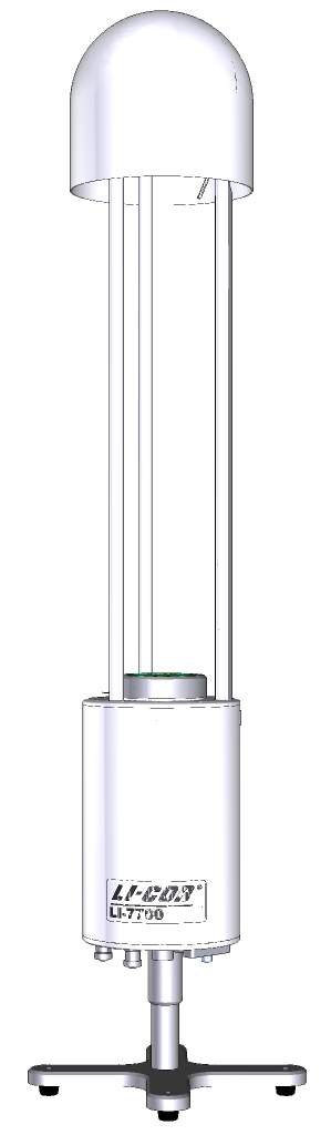
1. Mount the LI-7700 in its stand
Always use the stand (9977-067) while working indoors. It threads into the mounting post.
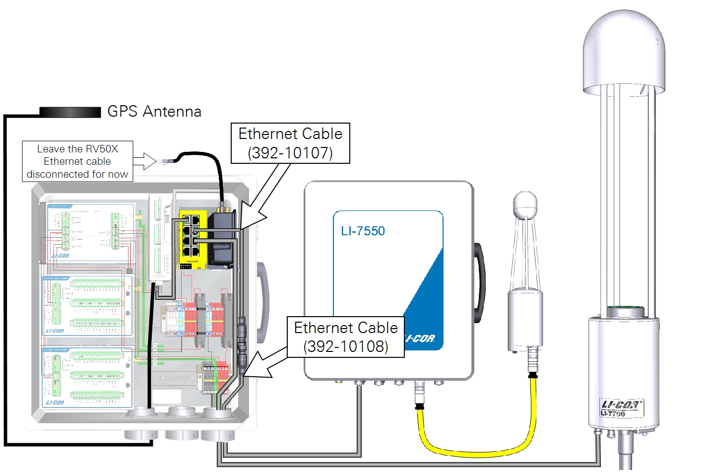
2. Connect the power and Ethernet cables to the LI-7700
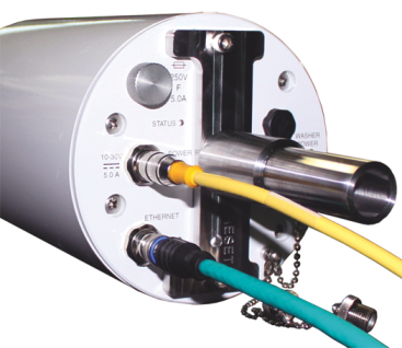
Attach the power cable (part number 9975-030) to the Power connection. Align the notch in the cable with the notch in the connector and push straight in. Connect the Ethernet cable to the Ethernet connector. Tighten the connectors securely.
3. Connect the power cable
Caution: Powering the LI-7700 with reversed polarity will blow the fuse.
If the power supply has a breaker, keep it OFF for now. Attach the red lead to the positive (+) terminal and the black lead to the negative (-) terminal of a power supply (10.5 to 30 VDC power supply capable of providing 4 to 5 amps).
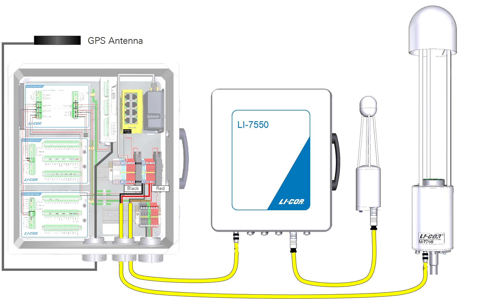
| From | Wire Color | To |
|---|---|---|
| Terminal 17 (bottom) | black | LI-7700 Power (-) |
| Terminal 20 (bottom) | red | LI-7700 Power (+) |
4. Connect the Ethernet cable to the network switch
Connect one terminal of the 5-meter Ethernet data cable (part number 392-10108) to the connection labeled Ethernet on the LI-7700. Attach the other terminal to the 0.3-meter Ethernet cable (part number 392-10107).
5. Power on the LI-7700
The LI-7700 powers on when power is supplied. Turn the breaker to the ON position. It will take 30 to 60 seconds to boot up. The Power LED and Status LED will be solid after instrument completes start-up.
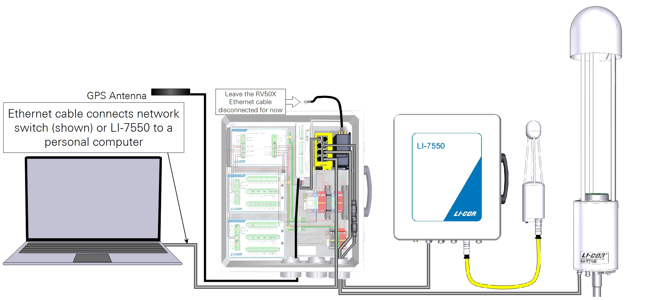
6. Connect the network cable to a computer
Attach the Ethernet cable to the network switch or directly to the network port on your computer.
7. Launch the software and connect to the LI-7700
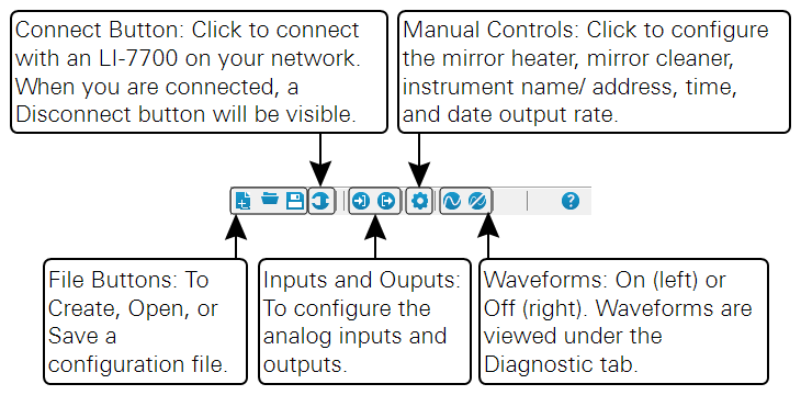
Start the LI-7700 application. Click Connect ( ), select Ethernet, select the LI-7700 under Select Instrument menu. Click Connect.

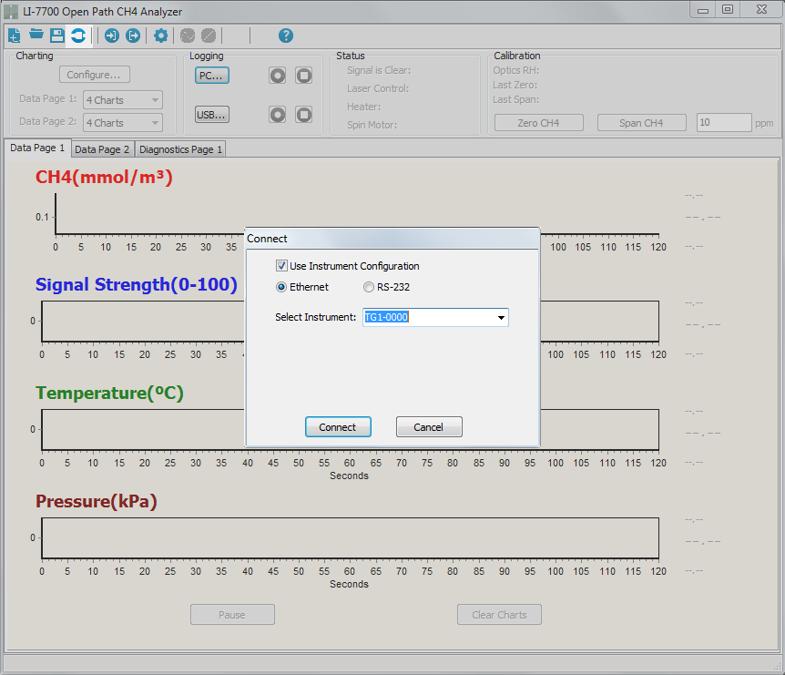
If the instrument is not on the list, wait about 30 seconds for the instrument to finish starting up, then re-launch the software and try to connect again.
- Check the firmware version. Click Help (
 ) > About. Check the PC Application Version and Embedded Version. If different from the Embedded and Interface versions at licor.com/support/LI-7700/software.html, download the new versions and update as described in Updating the software.
 - If you are connecting the instrument to an RV50X cellular gateway, set the IP address as described in the RV50X instruction manual from LI-COR.
The following section describes operating temperature range settings, mirror cleaner settings, mirror heater settings, and other options. When the LI-7700 settings are changed, they are implemented to whichever LI-7700 is connected to the interface. The LI-7700 starts up with the latest configuration.
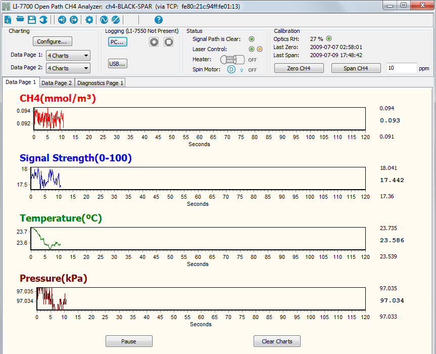
Software tour
After connecting to an LI-7700 data will begin streaming to the graphs. The graphs are set to auto-scale the y-axis by default, so do not be alarmed by the appearance of “noisy” signals.
Toolbar
The toolbar buttons activate the following options:
Control panel
Four groups of settings and operation parameters are displayed in this portion of the main window:
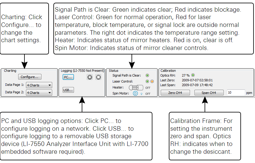
Chart tabs
Three pages (tabs) display the live data stream. Configure the data pages with the Configure button in the Charting frame described below. The Diagnostics page displays the instrument waveform, which is turned on or off with the Waveform button described above.
Charting
Two charting pages are visible, and each of these pages can display up to four charts. The charting pages are the two tabs called Data Page 1 and Data Page 2 in the main view. To configure the charts, select the tab with the charts you’d like to configure, then click the Configure button in the Charting frame of the main view.
Configure charts
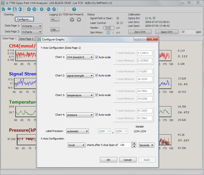
In the Configure Graphs window, you can turn automatic scaling “on” or “off” with the Auto-scale check box. When automatic scaling is on, the software retains a record of the maximum and minimum values encountered and scales the graph accordingly. If you click the Clear Charts button in the main window the chart scaling will reset.
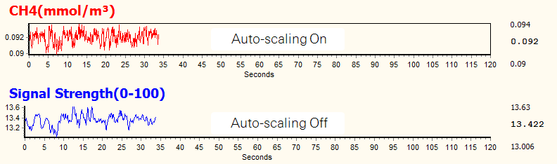
Automatic scaling can be turned on or off simply by double clicking on a graph in the main view. When automatic scaling is on, the graph will have a frame. When automatic scaling is off, the frame will be open, as shown below.
Operating temperature range
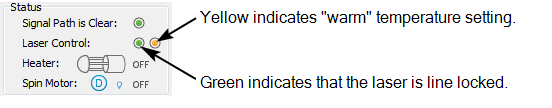
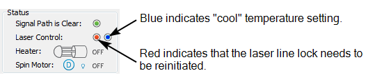
Two operating temperature ranges are available: -25 °C to 25 °C (cool) and 0 °C to 50 °C (warm). Select the temperature range setting that reflects the expected temperatures in the environment where you will deploy the LI-7700. If the wrong temperature setting is selected, the instrument may be unable to maintain the required temperature in the internal controls, and thus lose line lock (and it will not record methane data).
The current setting is indicated by either a blue (cool) or yellow (warm) indicator in the main window.
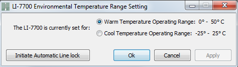
To change the setting, click on the yellow or blue indicator. This will open the window shown below, where you can change the setting.
After changing the temperature range setting, it may take up to 5 or 10 minutes for the block temperature to adjust before the instrument returns to normal operation. Look at the Diagnostics Page 1 tab and observe the Block Temperature setting. The Actual and Set temperatures should be within about 1.5 °C after the temperature adjusts.
Important: After changing the operating temperature range, be sure to re-zero and span the analyzer using high-quality (1% or better methane in air) calibration gases.
If the instrument is unable to achieve line lock once the new operating temperature range is established, click the Initiate Automatic Line Lock button in the temperature range setting window. This will instruct the instrument to re-try the automatic line lock routine.
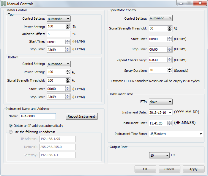
Manual controls
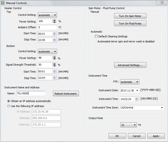
The Manual Controls window provides access to mirror temperature controls (see Mirror heater controls), mirror cleaner settings (see Mirror wash and spin settings), instrument time, date, and time zone (see Setting the time), IP address (see Instrument name and IP address), and output rate (see Output rate).
Changes will be implemented immediately to the connected LI-7700 when you click Apply or OK. These settings will be saved in the LI-7700 or they can be saved as a configuration file (see Configuration files).
Note on Embedded Software Versions: Embedded software (installed on the LI-7700) version 1.0.19 or newer displays the improved spin motor fluid pump controls (see Figure 2‑4).

Note on Embedded Software Versions: Embedded software version 1.0.14 and older displays the older spin motor - fluid pump controls shown in Figure 2‑5. We recommend that you install the newest embedded and desktop software to get the best performance from the instrument. See licor.com/support/LI-7700/software.html to get software updates.
Mirror heater controls
Mirror heaters serve to keep the mirrors free of condensation and frost. They are configured in the Manual Controls window in the heater control frame. See Table D‑1 to learn about power requirements for the heaters.
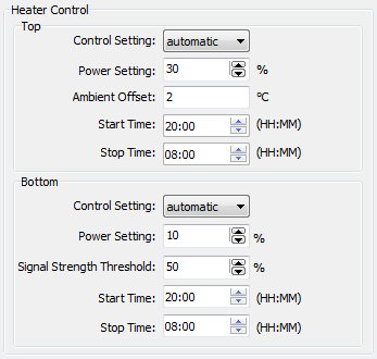
- Control Setting: Can be On, Off, or Automatic. Setting to On enables power and ambient offsets for the upper mirror and power settings for the lower mirror. The Automatic setting enables all possible controls.
- Power Setting: Specifies how much power is delivered to the mirrors. In environments with light condensation, power settings of 10% or less should be adequate. Settings near 100% should be reserved for circumstances in which severe ice buildup is expected.
- Ambient Offset: Specifies how far above the ambient temperature (as measured by the optical path thermocouple) the mirror is heated to. This setting applies only to the upper mirror.
- Signal Strength Threshold: (RSSI) for the lower mirror heater. It is enabled when the Control Setting is set to Automatic.
- Start Time and Stop Time: Specify when the mirror heaters are on. These are available only when the Control Settings are Automatic.
With the settings shown above, the LI-7700 will deliver 30% of the maximum possible heater power, as needed to keep the mirror 2 °C above ambient temperatures between 8:00 pm (20:00) and 8:00 am (08:00) to the upper mirror. The lower mirror will be heated with 10% of maximum possible power, only if the signal strength is below 50%, between 8:00 pm (20:00) and 8:00 am (08:00).
Note: It may take up to 60 minutes for the mirror to reach the set temperature. Account for this when setting the start and stop times.
To save power, set the mirror heaters to operate when condensation is likely. Set them to heat as little as is needed to keep the mirrors free of condensation. Mirror heater power consumption is linear with the setting. Thus, a setting of 100% requires about 8 W, whereas a setting of 10% requires about 0.8 W.
Determining appropriate mirror heater settings
The mirror heaters serve to remove or prevent the buildup of condensation on the mirrors. The best way to determine which settings are best for your environment is through experimentation. The following guidelines should serve as a starting point:
- Estimate when condensing conditions begin and end, and set the mirror heater start and stop times accordingly.
- Refer to a weather forecast or recent meteorological records. It is easier to prevent condensation than it is to remove condensation, so set the heaters to preempt the formation of dew.
- Estimate how far below the dew point temperature the actual temperature will fall.
- Use this to determine power settings and upper mirror ambient offset. If the predicted temperature is only a little below the dew point, a power settings of <10% with an ambient offset (upper mirror) of 1 °C may work fine. Power settings close to 100% should be reserved for extreme conditions where ice buildup is expected.
- Check your data.
- If you find data loss or reduced RSSI readings during condensing conditions, it will be worthwhile to boost the power settings or lengthen the time window during those periods.
Mirror wash and spin settings
Note: The Windows software described here is version 1.0.5. This desktop software is backwards compatible with LI-7700s running all versions of the embedded instrument software. If your embedded instrument software is up-to-date, see Embedded firmware 1.0.19 and newer. However, if your embedded instrument software is not updated, refer to Embedded firmware 1.0.14 and older for a description of the mirror cleaner settings. We recommend that you download the new instrument firmware from licor.com/support/LI-7700/software.html and install it on the LI-7700 to use the improved mirror cleaner algorithm.
Embedded firmware 1.0.19 and newer
The mirror cleaner provides the capability to automatically apply a cleaning solution (referred to as "washer" hereafter) to the lower mirror and to expel the cleaning solution and debris using centrifugal force (referred to as "spin" hereafter). You can configure the washer and spin motor timing separately or together to suit a wide range of conditions. The simplest way to configure the mirror cleaner is to use the automatic Default Cleaning Settings provided by the software. This combination of settings is suitable for a wide variety of settings.
Note: The pump is not designed to operate below freezing temperatures. Therefore, is set to disable when the temperature falls below -10 °C.
The cleaning settings are set in the Manual Controls window. The washer and spin motor can be controlled independently of each other.
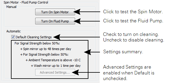
Manual Spin Motor - Fluid Pump Controls are simply to test the spin motor and pump. Note that the pump will run if you click Turn On Fluid Pump. If you have all the hardware put together and fluid in the reservoir, this could make a mess of your lab, spray cleaning fluid onto your laptop, lab technician, academic adviser, or anything else within range of the spray nozzle. Therefore, we recommend that you use discretion when you click this button.
To extend the life of the pump, refrain from running the pump dry for long periods.
If you find that the Default Cleaning Settings are suitable for your needs, you can activate them with the check box. If you find that they are not satisfactory, or if you wish to try out some other settings, clear the box and click Advanced Settings..., which provides you with more control over the settings.
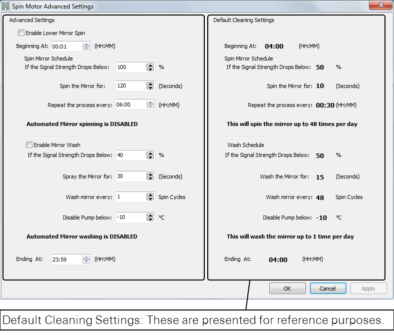
The Advanced Settings options are used to develop your own cleaning schedule. The Default Cleaning Settings are given to use as a reference.
- Enable Lower Mirror Settings: Check this box to configure the Spin settings. Clear it to use default settings (or disable it entirely).
- Beginning at HH:MM: Set the time to activate the mirror cleaner algorithm.
- Spin Mirror Schedule: Here you configure the conditions to activate the spin algorithm.
- If the Signal Strength Drops Below: Set the lower bound for the signal strength. If the signal strength drops below this (from a dirty mirror, for example), the spin motor will activate.
- Spin the Mirror for (seconds): The duration (number of seconds) of the spin.
- Repeat the process every: The amount of time that should pass between each spin. Note that the spin cycle will repeat until the signal strength gets above the lower threshold.
Summary: The bold note is to inform you of the maximum number of times per day that the mirror will spin, according to the settings.
- Enable Mirror Wash: Check this box to configure the fluid pump settings. Clear it to use the default settings or disable it entirely.
- If the Signal Drops Below: Set the lower bound for the signal strength. If the signal strength drops below this (from a dirty mirror, for example), the mirror cleaner algorithm will activate.
- Spray the Mirror for (seconds): The duration (number of seconds) of spray.
- Wash mirror every X Spin Cycles: The number of spin cycles that should include a wash. Typically, one wash per day should be sufficient, but you may need to change this setting for dusty sites.
Summary: The bold note is to inform you of the maximum number of times per day that the mirror will be washed.
Embedded firmware 1.0.14 and older
In the older instrument embedded software, the mirror - washer unit settings provided less intuitive controls, which lead to undesirable performance under some circumstances. If your instrument is running embedded firmware version 1.0.14 or older, however, the new desktop software will still display the old control interface. This is described below.
There are two components involved with the self-cleaning mirror – the mirror spin motor, which is in the lower housing, and the washer assembly. During the cleaning cycle, the pump and spin motor run simultaneously for the first part of the duration, and the spin motor alone runs for the last 10 seconds of the duration. This provides two benefits: Any drops that fall from the nozzle will be cleared by the spinning mirror, and it allows the mirror to spin without using washer fluid. Spin Motor Controls are in the Manual Controls window.
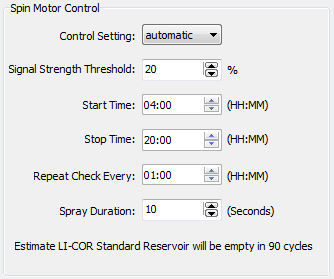
- The Control Setting can be On, Off, or Automatic. Change the setting to Automatic to enable the remaining controls.
- Signal Strength Threshold refers to a threshold (Received Signal Strength Indicator, or RSSI). If the laser signal strength falls below this threshold, the mirror spin motor and washer pump will activate according to the other settings.
- Start Time and Stop Time specify the period of the day in which the mirror cleaner can activate. Set both to 00:00 to allow mirror cleaning for 24 hours a day.
- Repeat Check Every sets the interval at which the instrument re-checks the RSSI value. If the RSSI value is below the Signal Strength Threshold (#2), then it will repeat the cleaning cycle according to the remaining parameters.
- Spray Duration: can be set from 0 to 110 seconds. A setting of 0 will result in no spray, but the mirror will still spin for 10 seconds if the RSSI is below the signal strength threshold.
With the settings shown above, if the signal strength is below 20%, the LI-7700 will initiate a 20 second cleaning cycle starting at 4:00 am (04:00). If the first cleaning cycle fails to raise the signal strength to above 20%, it will repeat every hour until 8:00 pm (20:00) or until the signal strength is above 20%.
Figure 2‑6 shows how the LI-7700 uses the Spin Motor Control settings:
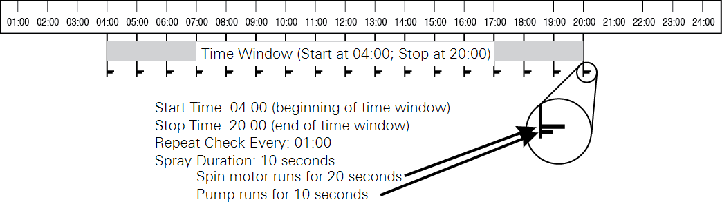
If the RSSI value is below the “Signal Strength Threshold”, a cleaning cycle will be initiated according to the “Repeat Check Every” setting. The pump always runs for 10 seconds less than the spin motor. Set the “Spray Duration” to 0 seconds to spin the mirror for 10 seconds without spraying any fluid.
Important: The use of a low signal strength threshold (e.g. ~10%) may result in “noisier” data as the signal strength gets lower. Check your data to observe this, and choose a setting that is within the noise tolerance that you prefer. Conversely, a high signal strength threshold (e.g., 80%) will cause the washer fluid to be used more quickly. Also, the spinning mirror will cause perturbations in the pressure measurement. Data collected while the spin motor is active should not be used.
Note: The 7700-101 is equipped with an inlet connection that can be used to attach a secondary washer reservoir. In environments where the washer fluid is used quickly, a secondary washer reservoir can be used to refill the 7700-101 reservoir. This will require a pump or siphon to transfer fluid from the secondary reservoir to the 7700-101 reservoir.
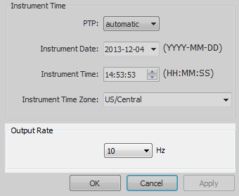
Setting the time
The LI-7700 is shipped with the time set at the factory. To set your local time, connect to the LI-7700 and open the Manual Controls window. Set the PTP: field to automatic. Select the desired time zone. Click Apply or OK.
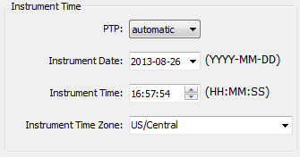
You may also adjust the time if desired, but these adjustments apply to the Unix time stamp as well. Therefore, be sure that the instrument time and date match your local time and date and that you have set the correct time zone.
The time stamp in each file header shows the instrument time and time zone. The time stamp associated with each data record will always include Unix time, but you can choose to output the instrument time and date as well. Unix time is in two fields: seconds and nanoseconds. Conventional time includes the date and time resolved to seconds. The nanoseconds field can be used to resolve sub-second time stamps.
About LI-7700 time keeping
Three aspects of time keeping in the LI-7700 are described here – the basis for the actual time (Unix, aka POSIX), the protocol for determining the actual time (Precision Time Protocol), and user-settable time zone and time.
The LI-7700 is a network-based instrument and it is possible for multiple users to log data from a single instrument over multiple TCP/IP connections. Consequently, the instrument uses Coordinated Universal Time (UTC) for its onboard timekeeping tasks. As such, the default time stamp is UTC based, but local time can be set as well.
The LI-7700 internal clock uses Unix time as a standard. Simply put, this is seconds elapsed since the Unix Epoch of 00:00 Coordinated Universal Time (UTC) Jan. 1, 1970 (or 1970-01-01T00:00:00Z ISO 8601). For example, the time stamp 1262884605 translates to 01/07/2010 at 05:16:45 UTC. The date and time are converted into a conventional display format (YYYY-MM-DD; HH:MM:SS), and adjusted based on the time zone settings that you select.
The LI-7700 uses the Precision Time Protocol (PTP) time keeping system. PTP is a high precision time synchronization protocol for networked measurement and control systems. Devices controlled with PTP can maintain accuracy in the sub-microsecond range with a sufficiently accurate master clock. PTP is defined in the IEEE 1588-2002 and 1588-2008 standards, officially entitled “Standards for Precision Clock Synchronization Protocol for Networked Measurement and Control Systems.” A detailed summary of IEEE-1588 is available at www.ieee1588.com. Full documentation is available for purchase from the Institute of Electrical and Electronics Engineers (IEEE) at www.ieee.org.
The basic principle behind the PTP is that the best time keeping can be accomplished with multiple networked devices by synchronizing all the device clocks to the most precise clock on the network. Each clock on the network has a rating that indicates its relative accuracy. The IEEE 1588 protocol specifies the use of a Best Master Clock algorithm to determine which clock on the network is the most accurate. On a network, the most accurate clock becomes the master clock and all other clocks sync to the master clock.
The software implementation of PTP in the LI-7700, which uses the instrument clock, provides accuracy in the 10 microsecond range. Implementation of PTP is most important when the LI-7700 is used in combination with the LI-7550 Analyzer Interface Unit or other network-based sensors.
Time keeping settings
Three time-keeping settings are available in the Manual Controls window. They are:
- Automatic: The LI-7700 searches the network and syncs to the most accurate clock using the Best Master Clock algorithm. The LI-7700 should use this setting in most circumstances.
- Preferred: The LI-7700 uses its own internal clock unless it finds a better clock on the network. The LI-7550 should use this setting in most circumstances.
- Slave: The LI-7700 syncs to another clock. It will search the network and synchronize to the best clock.
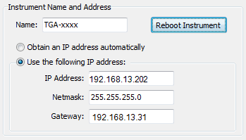
Instrument name and IP address
The instrument name and IP address are given in the Manual Controls window. To rename your LI-7700, simply type the new name of your LI-7700 into the name field and click OK or Apply. Then reboot the instrument.
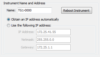
The communication interface to the analyzer head is by Ethernet. More specifically, it is by the IPv6 Ethernet Protocol. As such, it is generally not necessary to configure a static IP address for the instrument if the instrument name is known. The instrument broadcasts its name onto the network, and the LI-7700 PC software looks for that broadcast and then populates the Connect window accordingly.
Configuring for cellular communication
For the RV-50X, we recommend setting the LI-7700 IP Address and other instruments in the system as described below.
| Device | Public Start Port | Public End Port | Protocol | Host IP | Private Start Port |
|---|---|---|---|---|---|
| LI-7700 | 7700 | 0 | TCP | 192.168.13.202 | 7700 |
The output rate setting determines the signal averaging done by the digital filter. To avoid aliasing (only a concern for co-spectra, not for fluxes), the LI-7700 output rate should be set at a frequency greater than or equal to 2 times the desired bandwidth, also referred to as the Nyquist frequency (e.g., for a bandwidth of 20 Hz, set the output rate to 40 Hz). This is set in the Manual Controls window.
Bandwidth is the frequency at which the indicated amplitude is 0.707 of the real amplitude.
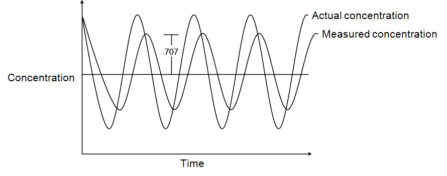
Bandwidth is useful for characterizing real-world behavior in which there are fluctuating gas concentrations. Given a sinusoidal oscillation of concentration, the instrument’s ability to measure the full oscillation amplitude diminishes as the oscillation frequency increases.
Logging data to a computer
This section describes how to configure logging to a Windows computer on the same network as the LI-7700. PC datalogging uses the LI-7700 Ethernet output.
- Establish communication with your LI-7700.
- Click on the PC… button in the Logging frame of the main view.
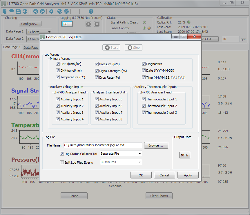
- Note: Auxiliary Inputs 5 through 8 can only be logged when an LI-7550 Analyzer Interface Unit is used.
- Select the variables that you’d like to log. Click Apply.
- Choose a directory that the files will be written to, choose whether to log the Status record, and whether it will be part of the data file or a separate log file. Choose how often to split the log files (from 15 minutes to 24 hours). Click Apply.
- Click the button under Output Rate to open the Manual Controls window), where you can change the output rate. Click Apply in the Manual Controls window.
- Click Apply or OK in the Configure PC Data Logging window.
The Start button will be available (no longer grayed out). You can click Start ( ) in this window to begin logging immediately or click OK to return to the main view where a second Start button (
 ) will be active.
When actively logging, the control settings will be grayed out, a green indicator will appear in the main view, and the Stop button will become active. If you are logging data to a PC, be sure to disable sleep mode or logging will stop.
Logging status columns
Status data (see Status columns) can be logged to the data file, logged to a separate file, or not logged. To log status data, check the Log Status Columns To: check box, then select Separate File or Log File. Status data are logged at 2 Hz. If you select Log File, the status data will be interspersed with the data record.
Splitting files
To help limit the size of individual files, log files can be split on a periodic basis. The method of splitting is based on the instrument clock, rather than on elapsed time. As such, the file will split when the instrument time crosses a user-specified interval. For example, if the application is set to split the log file every 15 minutes and the logging session starts at 11:25, the first split will occur at 11:30. The second split will occur at 11:45, and so on.
Configuration files
The configuration file is an XML text file that includes instructions that specify the operational parameters of the instrument. You can create a configuration file from the instrument, or upload a configuration file to the instrument.
Creating an instrument configuration file
The following procedure describes how to create a new instrument configuration file. See Configuration grammar for more information on configuration files.
- Launch the LI-7700 Windows® software.
- Be sure the LI-7700 software is not connected to an LI-7700.
- If needed, click the Disconnect button. Optional: click the New Instrument Configuration button to restore default settings.
- Click on the Manual Controls button.
- Set the controls as desired. Click OK or Apply then OK to set the new configuration. Repeat this for the Auxiliary Inputs and LI-7550 Outputs if desired.
- Click the Save button
 .
. - A Save As... window will open. You can select a directory anywhere on your computer or network. The file will have a “.l77” extension.
Loading a configuration file
The following procedure describes how to implement a configuration file.
- Be sure the LI-7700 is powered “on” and connected to your computer or network with the Ethernet connection.
- Launch the LI-7700 software and connect with the LI-7700.
- Click on the Open button
 . The Open dialog box will appear. Navigate to the directory that has the “.l77” configuration file.
 - Select the file and click Open.
Note: When you connect to an LI-7700, at the top of the Connect dialog box, there is a Use Instrument Configuration check box. Be sure it is checked in order to prevent overwriting the current LI-7700 configuration.