
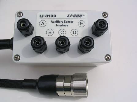
The auxiliary sensor interface attaches to the side of the analyzer control unit and allows for connection of your choice of sensors or an alternative power supply. Data from these sensors are logged in the data file under the headers V1 to V4 (voltage inputs) and the headers T1 to T4 (thermocouple inputs).
The auxiliary sensor interface is O-ring sealed, and has connections for up to 4 thermocouples (types E, J, or T, or raw), and 4 general purpose input voltage channels, any of which can be configured to measure a soil moisture probe, thermistor, or other voltage input.
Sensors can be powered externally or by the LI-8100A with a constant 5 VDC source. There is also a switched 5 VDC power supply used for moisture sensors. The auxiliary sensor interface also has a 10.5-28 VDC input (3 A minimum) for use with external power.
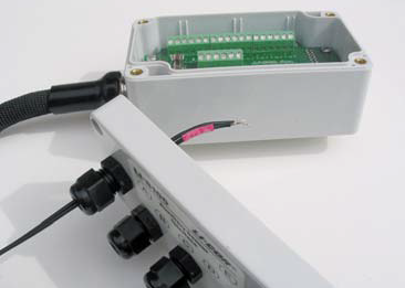
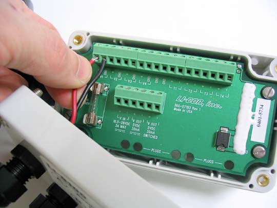
Open the box by loosening the 4 Phillips head screws in each corner of the auxiliary sensor interface module and remove the top cover.

There are 2 terminal strips, with connections given in Figure 3‑6.
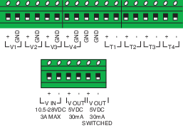
| Terminal | Label | Description |
|---|---|---|
| 1 | V1+ | Voltage input 1 positive |
| 2 | V1 GND | Voltage input 1 ground |
| 3 | V2 + | Voltage input 2 positive |
| 4 | V2 GND | Voltage input 2 ground |
| 5 | V3 + | Voltage input 3 positive |
| 6 | V3 GND | Voltage input 3 ground |
| 7 | V4 + | Voltage input 4 positive |
| 8 | V4 GND | Voltage input 4 ground |
| 9 | GND | Ground |
| 10 | GND | Ground |
| 11 | T1 + | Thermocouple input 1 positive |
| 12 | T1 - | Thermocouple input 1 negative |
| 13 | T2 + | Thermocouple input 2 positive |
| 14 | T2 - | Thermocouple input 2 negative |
| 15 | T3 + | Thermocouple input 3 positive |
| 16 | T3 - | Thermocouple input 3 negative |
| 17 | T4 + | Thermocouple input 4 positive |
| 18 | T4 - | Thermocouple input 4 negative |
Power in and out terminals are given in Table 3‑2
There are 5 compression style strain relief cable glands on the auxiliary sensor interface. To attach your sensor(s) or power supply to the auxiliary sensor interface:
- Loosen the four screws and remove the top cover of the box.
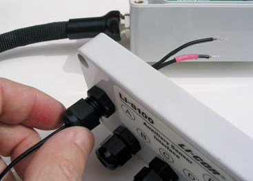
- Remove the cap from any of the 5 glands by turning counter-clockwise.
- Pass the wires through the top of the gland cap first, and then through the gland.
- Screw the cap on slightly, but don’t tighten yet. If the wire is too small, wrap it in santoprene tubing to increase its diameter and to help seal it in the gland plug.
Note: When inserting wires through the gland plugs on the auxiliary sensor interface, it is important that a water-tight seal is formed when the gland plug cap is tightened. If you are have poor data from sensors that are connected to the box, check to see if the wires are tightly sealed. If they are loose, you may need to encase bare wires in a short piece of sheathing material to improve the seal.
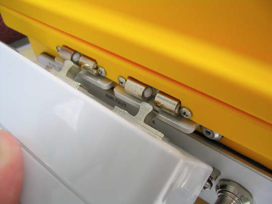
- Use a small slotted screwdriver to loosen the appropriate screw terminal, insert the wire lead into the terminal, and tighten the screw terminals.
- Make a note of which gland the wires are passing through (A, B, C, D, or E), and to which terminal the wires are connected (e.g. A/T1, B/V3, etc.). This information will be needed later when you enter the sensor calibration coefficients into software.
- Pull gently on the wires to remove excess slack from inside the box, re-attach the interface top cover, and tighten the gland cap.
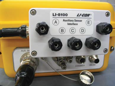
- When you have finished installing all of your sensors and/or a power supply, attach the auxiliary sensor interface cable connector to the connector on the side panel of the analyzer control unit labeled AUX SENSOR.
- Snap the auxiliary sensor interface onto the console.
NOTE: In order to achieve a weather-tight seal, the interface cable connector must be tightened until it completely covers the O-ring seal on the analyzer control unit connector. When the connector feels tight, push in and wiggle it while continuing to tighten until the O-ring is covered.
-
Always leave plugs in place in any unused gland plugs to prevent water and insects from getting inside the box.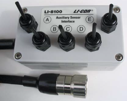
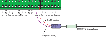
The 6000-09TC Omega soil temperature probe terminates with two bare wires for connection to the auxiliary sensor interface. Thermocouple channels 1-4 (T1-T4) can be used with the Omega soil temperature probe.
![]()
In the PC Software:
Click Chamber Measurement (Ctrl + M), then select Thermocouples.
Select type E for the Omega probe for the specified channel (Thermocouple 1 in Figure 3‑7).
![]()
In the App:
Tap LI-8100A > Auxiliary Inputs, the select the thermocouple to configure (Thermocouple 1 in Figure 3‑7).
Select E for the Omega Probe.
Connecting the GS1 soil moisture probe
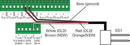
The GS1 soil moisture probe is compatible with voltage channels 1-4 (V1-V4). The 8100-205 model has red, bare, and white wires that connect to V4 (+), V4(GND), and V OUT 5VDC Switched(+), respectively, as shown in Figure 3‑8.
![]()
In the PC Software:
Click Chamber Measurement (Ctrl + M) > Port Setup, then select the V4 tab (V4 in Figure 3‑8).
Select Soil Moisture Probe and enter m: 0.494 and b: -0.554.
![]()
In the App:
Tap LI-8100A > Auxiliary Inputs, then select the voltage input to configure (V4 in Figure 3‑8).
Select SM (soil moisture) and enterSlope: 0.494 and Offset: -0.554.
Connecting the EC-5 soil moisture probe
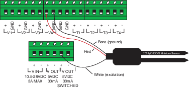
The ECH2O soil moisture probe is compatible with voltage channels 1-4 (V1-V4). The 8100-202 model has red, bare, and white wires that connect to V4(+), V4(-), and V OUT 5VDC SWITCHED(+), respectively, as shown in Figure 3‑9.
![]()
In the PC Software:
Click Chamber Measurement (Ctrl + M) > Port Setup, then select the V4 tab (V4 in Figure 3‑9).
Select Soil Moisture Probe and enter1m: 0.488 and b: -0.272.
![]()
In the App:
Tap LI-8100A > Auxiliary Inputs, then select the voltage input to configure (V4 in Figure 3‑9).
Select SM (soil moisture) and enter1Slope: 0.488 and Offset: -0.272.
Connecting the 8100-203 soil temperature probe
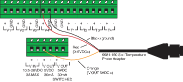
The 8100-203 soil temperature probe kit consists of a soil temperature probe (part number 8150-203) and a cable adapter (part number 9981-150) that connects to the probe. The cable adapter contains a resistor that allows the 8150-203 soil temperature probe to be used with the auxiliary sensor interface on the LI-8100A.
![]()
In the PC Software:
Click Chamber Measurement (Ctrl + M) > Port Setup, then select the V4 tab (V4 in Figure 3‑10).
Select Thermistor Input and click Set to Default or enter the coefficients:
![]()
In the App:
Tap LI-8100A > Auxiliary Inputs, then select the voltage input to configure (V4 in Figure 3‑10).
Select Therm (thermistor) and tap Set to Default or enter the coefficients:
a=1.1259e-3
b=2.3459e-4
c=8.6329e-8
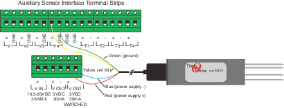
Connecting the Delta-T ThetaProbe
The 8100-204 Delta-T ThetaProbe has four bare wire leads for connection to the auxiliary sensor interface voltage channels 1-4 (V1-V4). The cable has red, blue, yellow and green wires that are connected to V OUT 5VDC SWITCHED(+),V OUT 5VDC SWITCHED(-), V4(+), and V4(-) respectively, as shown in Figure 3‑11.
![]()
In the PC Software:
Click Chamber Measurement (Ctrl + M) > Port Setup, then select the V4 tab (V4 in Figure 3‑11).
Select Soil Moisture Probe and enter m (Slope) and b (Offset) from Table 3‑3.
![]()
In the App:
Tap LI-8100A > Auxiliary Inputs, then select the voltage input to configure (V4 in Figure 3‑11).
Select SM (Soil Moisture) and enter Slope and Offset from Table 3‑3.
The 8100-204 uses different linearization coefficients, based on the organic content of the soil into which the probe is inserted. In general, if the soil is classified as a mineral soil, with < 7% organic content, the probe uses one set of coefficients, and if the soil is classified as an organic soil, with > 7% organic content, the probe uses a second set of coefficients.
It is possible to perform soil-specific calibration of the soil moisture probe to obtain linearization coefficients; refer to the ThetaProbe ML2x instruction manual for more information.
In general, temperature and moisture measurements should be made in close proximity to the CO2 flux measurement. Researchers have reported a strong correlation between soil CO2 flux and soil temperature (e.g., Hanson et al., 1993, Norman et al., 1992). Furthermore, soil temperature and moisture may vary significantly with depth (Hillel, 1982), and both are dependent on a number of site characteristics, such as exposure to light, shade, and wind.