
There is a Balston air filter in-line on the flow path leading to the IRGA optical bench. It is very important that incoming air be filtered. This is because any dirt in the optical cell will cause an immediate zero shift.
The optical bench can be removed and cleaned if necessary. If the optical path becomes dirty it may become difficult to span the analyzer. Excessive zero drift may also be observed if the optical path becomes dirty. If significant dirt accumulates in the optical bench, linearity errors that exceed the stated specifications can also result.
Follow these steps to clean the optical bench:
NOTE: Make sure that you are properly grounded to avoid any electro-static discharge events that can damage the internal components.
- Remove the air filters as described in Replacing the air filters.
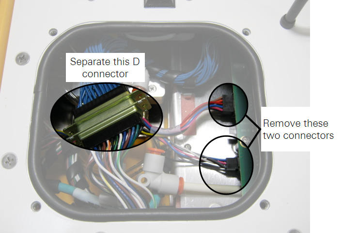
- There are three electrical connectors that must be removed.
- Two of them are just to the right of filters. Pull straight out on the connectors to remove them. The third is a large "D" connector.
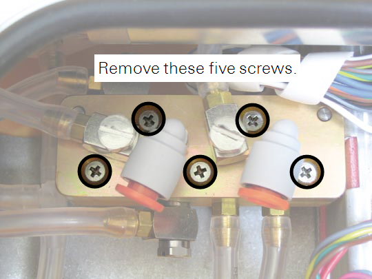
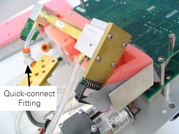
- Remove the two screws that hold the tube connectors to the top of the manifold.
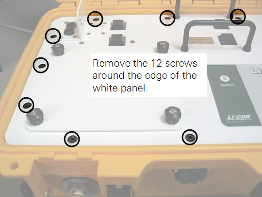
- Remove the twelve screws around the outer edge of the white panel, as shown below.
- Lift the analyzer control unit from out of the yellow case.
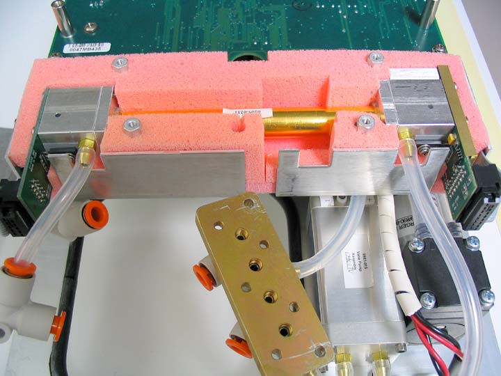
- Turn the control unit upside down. It will appear as shown below.
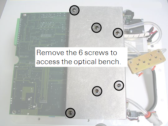
- Remove the six screws from the optical bench cover, as shown above.
- The optical bench will appear as shown below.
- Leave the tubes connected to the optical bench, and lift the bench out of the foam casing.

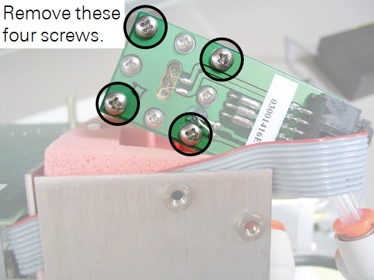
- There are four screws on the source and detector circuit boards that must be removed.
- Remove the four screws in the corners of the source housing circuit board, as shown below. Do not remove the remaining four screws.
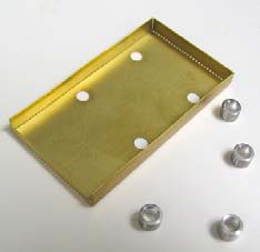
- Remove the four screws from the detector housing cover, as shown below. Note that there are some small standoffs inserted over the screws behind the cover; tilt the housing down when removing the cover so these standoffs don't get lost.
- The optical bench can now be removed.
- Note that there are O-rings on both ends of the optical bench. It is a good practice to replace the O-rings when cleaning or replacing the optical path.
- Swab the optical path.
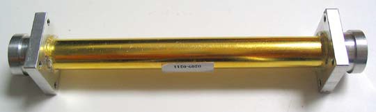
- There are a number of swabs in the spare parts kit. Dip one end of a swab into a 50:50 ethanol/water solution and carefully swab both ends of the optical bench, until there is no more visible residue. A mild solution of dish washing soap and water will also work. Do not use abrasive cleansers, as they can irreparably damage the gold plating on the optical bench.
- Use a reflector swab and carefully swab the gold-plated concave surface of the source housing, if necessary.
- If you need to clean out the hose barbs and/or replace the tubing connected to the source and detector housings, use a small pair of diagonal cutters to remove the tubing from the hose barbs. Use the cutters to pinch the tubing parallel to the hose barb axis, and then pivot the cutters over the hose barb tip; the tubing will pull off of the hose barb. Be very careful not to cut the tubing or scratch the hose barb with the cutters, as subsequent tubing connections may leak.
- Let the optical bench dry.
- Re-assemble the bench, making sure the O-rings are in place on both ends of the bench.
- Note that the orientation of the cylinder is not important; either end can be inserted into the source or detector housing.
- Re-assemble the LI-8100A case.
- Make sure that the foam insulation on the inside top cover is positioned over the optical bench; it is required for thermal stability.
- Perform zero and span calibrations as described in Calibrating the LI-8100A.