
This section describes basic maintenance and repair procedures for the analyzer control unit.
The LI-8100A instrument software is programmed into the instrument internal memory. It can be updated using an updater application available from the LI-COR technical support website at licor.com/support/home.html
We recommend running the most current software, if possible, unless there is a function that you need that is not supported by the current software (such as compatibility with Palm or Windows Mobile devices). Refer to the Software compatibility table for more details.
NOTE: The update may require 20-30 minutes to complete. If you are using the battery to power the LI-8100A, be sure that you have sufficient charge to operate the LI-8100A for 30 minutes or more.
- Power the LI-8100A off.
- Be sure the computer and the LI-8100A are connected via the RS-232 serial cable with serial-to-USB adapter, as described in First Things First.
- Locate the LI8100_update program, and double-click on the icon to start the program.
- Choose the serial port on your computer to which the LI-8100A is connected using the arrow keys.
- Click the Connect button.
- Turn the LI-8100A ON.
- The update will begin.
- A series of messages will appear in the window, as shown in Figure 9‑1.
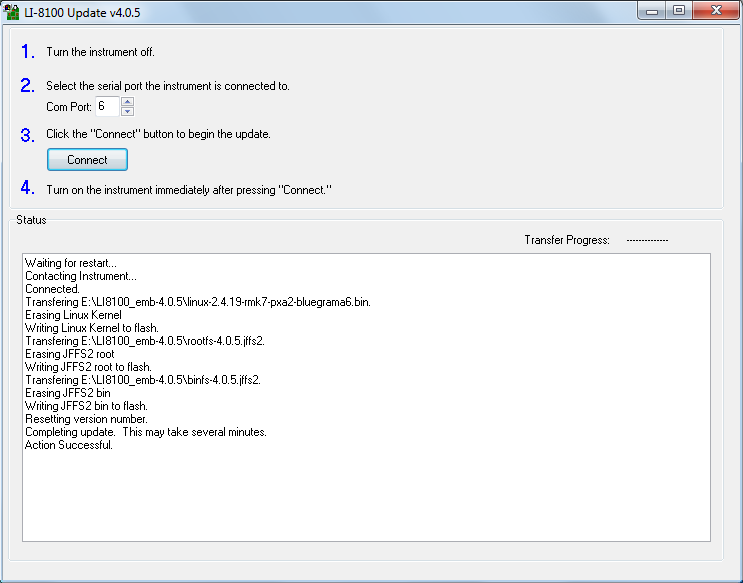
- Figure 9‑1. Progress messages appear in the Update window.
- Wait for the message ‘Action Successful’ to appear.
- In some cases, the ‘Action Successful’ message will not appear even though the update was successful; follow the steps below, and then start the LI-8100A Windows or mobile software application. Go to the View > Instrument Status to view the Embedded software version number to see if the version that you were updating was installed. If it was not, you may need to run the LI‑8100_update program again.
- Close the LI-8100A Update window.
- Turn the LI-8100A OFF, and then back ON.
- Wait 2 minutes or so, until the green Ready light on the LI-8100A keypad turns on.
- The LI-8100A instrument software is now ready to use.
NOTE: You should always run computer software that is compatible with the instrument software. Check the Software compatibility table for more information.
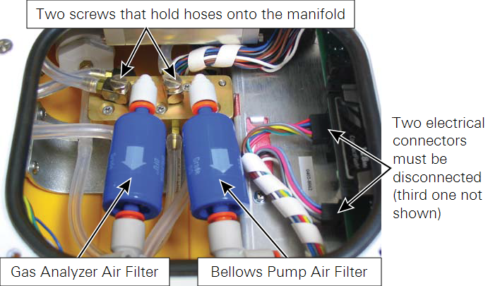
There are two Balston air filters located inside the analyzer control unit. One of the filters is on the flow path to the attached chamber, and the other is on the bellows air path, and is used only when the survey chamber is attached. The bellows air path draws air from outside of the analyzer control unit through a port on the front panel. This port also has a built-in filter, so the air filter on this line should not need to be changed with any regularity, if at all.
The air filter on the flow path will need to be replaced after about every three months of continuous use, depending upon the conditions under which the instrument is used. You can look at the clear Bev-a-line tubing to get a visual indication of how much dirt is present in the line, or alternatively, if the instrument zero and span settings are fluctuating widely (see Calibrating the LI-8100A), it may be time to change the filter. Follow these steps to replace the Balston air filters (there are two in the spares kit under part number 300-01961):
CAUTION: Never swap the bellows filter and the gas analyzer filter. Airflow through the bellows air circuit is bi-directional, meaning dirt can be introduced into the filter in both directions. If this filter is inserted into the gas analyzer air path, dirt can be blown into the gas analyzer, which will affect the calibration.
- Power the instrument off and disconnect the battery or external power source.
- Open the analyzer control unit case and remove the access panel by loosening the four thumbscrews.
- Remove the air filters by pressing the orange part of the quick-connect fittings toward the white part of the connector and pulling the filter out.
- Insert the new filters as shown in Figure 9‑2.