
If your LI-8100A fails to turn on when you press the power button, there is a possibility that a fuse has blown. There is one fuse inside each 6400-03 battery, one insed the auxiliary sensor interface, two fuses in the analyzer control unit, and two fuses in the Multiplexer. See Replacing the battery fuse if the battery will not charge or power the LI-8100A. See Multiplexer fuses if the instrument powers up from the battery, but will not power up from the Multiplexer. Continue in this section if the problem stems from the Auxiliary Sensor Interface or the Analyzer Control Unit.
Auxiliary sensor interface fuse
A fuse is located inside the auxiliary sensor interface. It protects the instrument from overcharges due to improper connection of an external power supply. To check this fuse, simply loosen the four screws on the auxiliary sensor interface cover and remove the cover.

The screws on the 8100-663 Auxiliary Sensor Interface cover are "captive" screws, meaning they are retained in the cover so they can't fall out. Loosen them until you can lift the cover off. If the fuse is blown, replace it with a spare 250V, 3A fast-blow fuse in the spare parts kit (part number 439-04215).
Analyzer control unit fuses
There are two fuses inside the analyzer control unit. One fuse protects the circuitry when powered from a battery attached to the LI-8100A battery connectors. The other protects the circuitry when powered from the auxiliary sensor interface or the multiplexer. In most cases these fuses will not blow; we recommend that you test the battery to make sure it is fully charged before attempting to check the fuses. If you have eliminated all other possibilities, follow these steps to check the analyzer control unit fuses:
- Troubleshoot the power issue:
- If the LI-8100A cannot be powered by the battery (and the battery is working properly), but can be powered through the auxiliary sensor interface or multiplexer, then the battery power fuse may have blown. In this case, follow this procedure and check the fuse for battery power.
- If the LI-8100A can be powered by the battery, but cannot be powered through the auxiliary sensor interface, then the auxiliary fuse may have blown. In this case, follow this procedure and check the fuse for auxiliary power.
- Power the instrument off and remove the battery or other external power source.
- Open the analyzer control unit case and remove the access panel by loosening the four thumbscrews.
- Mark one of the Balston air filters with a marker or piece of tape so you are able to return them to their original locations when reassembling the system.
CAUTION: Never swap the bellows filter and the gas analyzer filter. Airflow through the bellows air circuit is bi-directional, meaning dirt can be introduced into the filter in both directions. If this filter is inserted into the gas analyzer air path, dirt can be blown into the gas analyzer, which will affect the calibration.
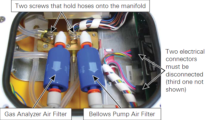
- Remove both air filters by pressing the orange part of the quick-connect fittings toward the white part of the connector and pulling the filter out.
- There are three electrical connectors that must be removed.
- Two of them are on a single wiring harness, just to the right of filters in the photo above; the third is about two inches further back from them, just beyond the edge of the access panel, as shown below. Pull straight out on the connectors to remove them. The large connector under the access panel can be difficult to reach; you can gently pull on the wire harness and slowly rock the connector back and forth to remove it, if necessary. When reinserting the connector, make sure that you check the pin alignment before pushing the connector into place, as the upper right hand side pins can easily become bent if misaligned.
- Remove the two screws that hold hoses onto the air manifold.
- Remove the twelve screws around the outer edge of the white panel.
- Lift the analyzer control unit from out of the yellow case.
- The battery power fuse (part number 439-04215) is located on the back of the control unit as you face the instrument. The circuit board is labeled 3A 250V at the location of the fuse.
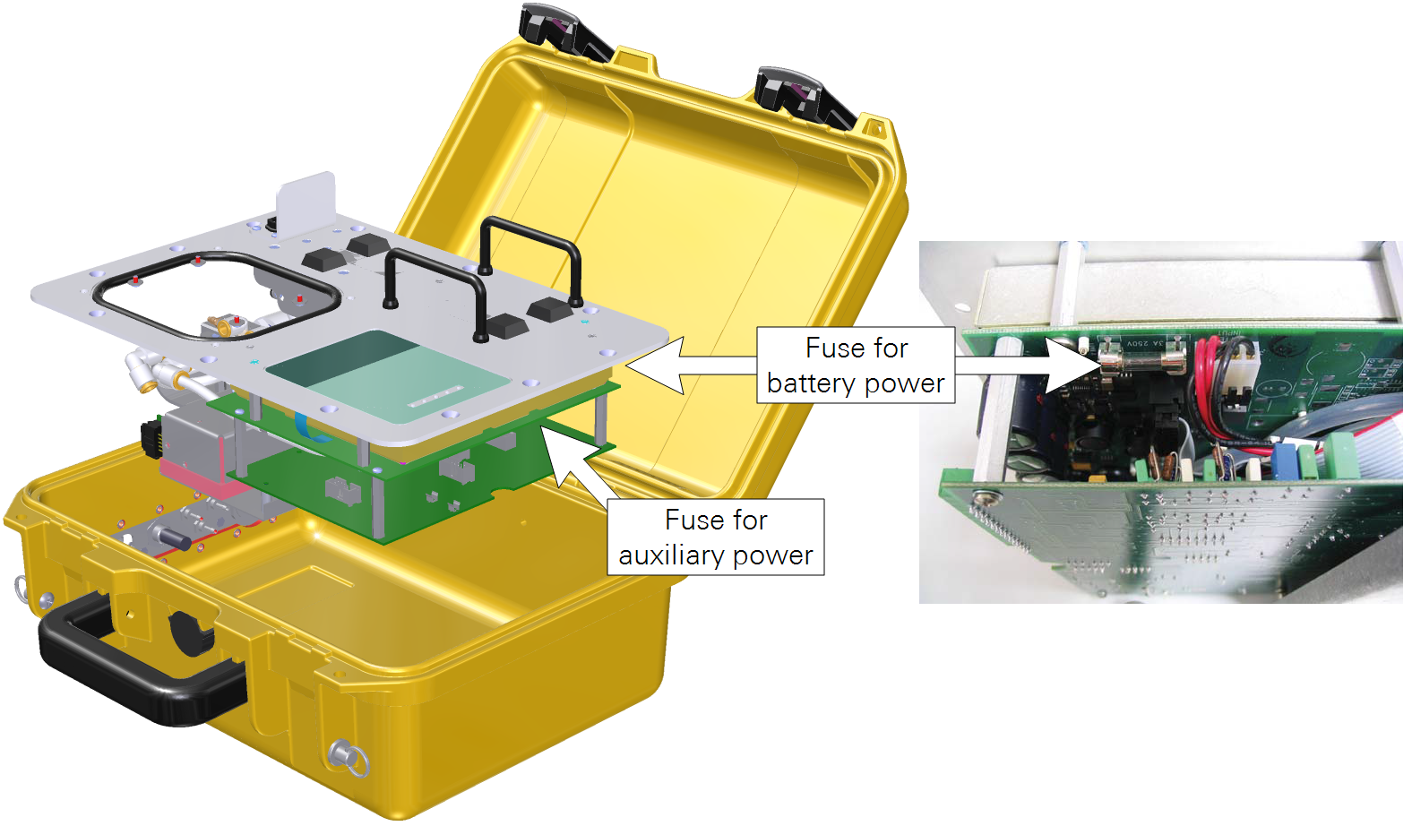
- The auxiliary power fuse is located on the right hand side of the control unit as you face the instrument. It is a 4A 250V fuse (part number 439-04482).
- Inspect the fuse and check it using an ohm meter. If a fuse has blown, replace it with an identical fuse from the spare parts kit.
- Test the system by powering it up. Then re-assemble the analyzer control unit.