The LI-8250 Multiplexer and 8250-01 Extension Manifold are designed to require little routine maintenance. Most of the components are modular and are intended to be easily replaced if needed.
Note: Before doing any maintenance or repairs to the components, first disconnect the instrument from the power source.
Replacing port air filters
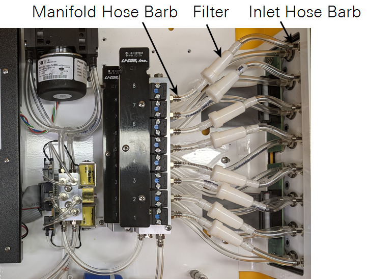
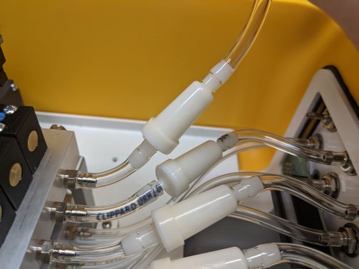
Air filters are located inline with the tubing between each of the eight port and the valve manifold. Eight spare filters (part number 9981-123) are in the spares kit. Filters may need to be replaced if you observe flow below 1.9 LPM or no flow rate.
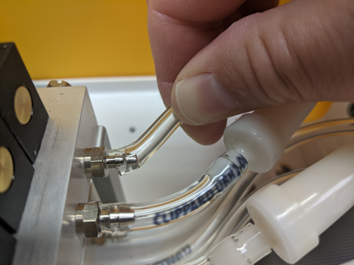
The tubing is attached with barbed fittings found at the air inlet and the valve manifold. This provides a secure, long-term connection. A good way to remove the filter is to cut a small, wedge-shaped section out of the tubing behind the hose barb. Small, general-purpose diagonal, flush, or shear cutters work well. Position the cutters so that you will not scratch or damage the hose barb as you cut.
Caution: Do not use a knife to cut along the hose because it may damage the sealing surface of the hose barb. Instead, use a clippers and be careful to avoid damaging the hose barb.
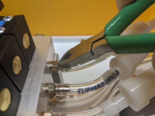
After cutting the wedge out of the tubing, pull the tubing firmly to the side (perpendicular to the fitting). The tubing will slide off with ease. Still, be careful to avoid injuring your knuckles when removing the tubing. Discard the old tubing and filter.
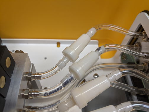
Attach the tubing to the hose barb on the valve manifold. Pay careful attention to the orientation of the new filter. There is a raised arrow on the outside of the filter. This arrow should point toward the valve manifold so that the wider end is toward the valve manifold.
The tubing on the other end of the filter is longer than required. Route the tubing to the hose barb at the air inlet. Leave a little slack and trim the hose to length before sliding it over the hose barb.
Replacing the system air filter
Filters may need to be replaced if you observe flow below 1.9 LPM or no flow rate. A blue Balston filter is between the valve manifold and the system manifold or pump. A replacement air filter (part number 300-01961) is in the spares kit.
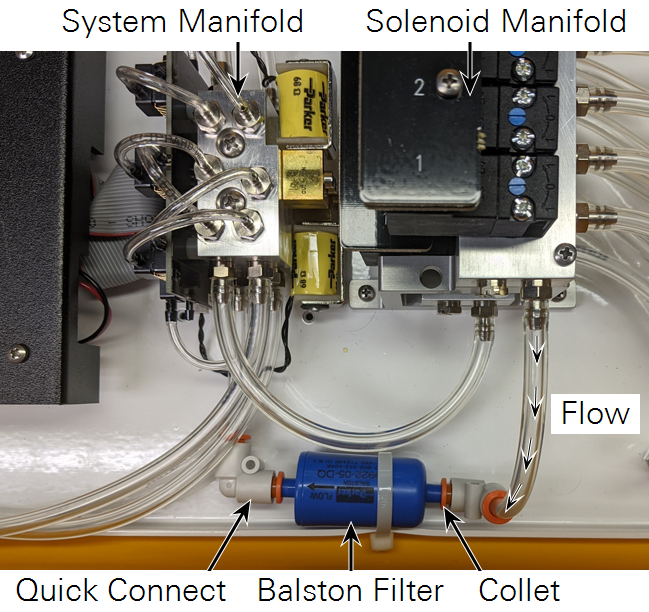
To remove the air filter, press in on the orange collets of the quick-connect fittings on both sides of the filter. Pull the quick-connect fittings off and slide the filter out of the strap.
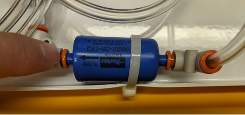
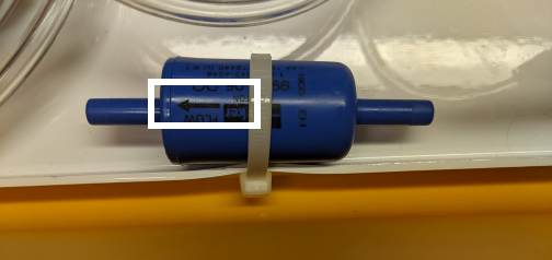
Slide the new filter into the strap. Note the direction of the flow from Figure 9‑6, and ensure the arrow on the filter is pointed with the direction of the flow. Then reconnect the quick-connect fittings to each side of the new air filter.
Replacing the fuse
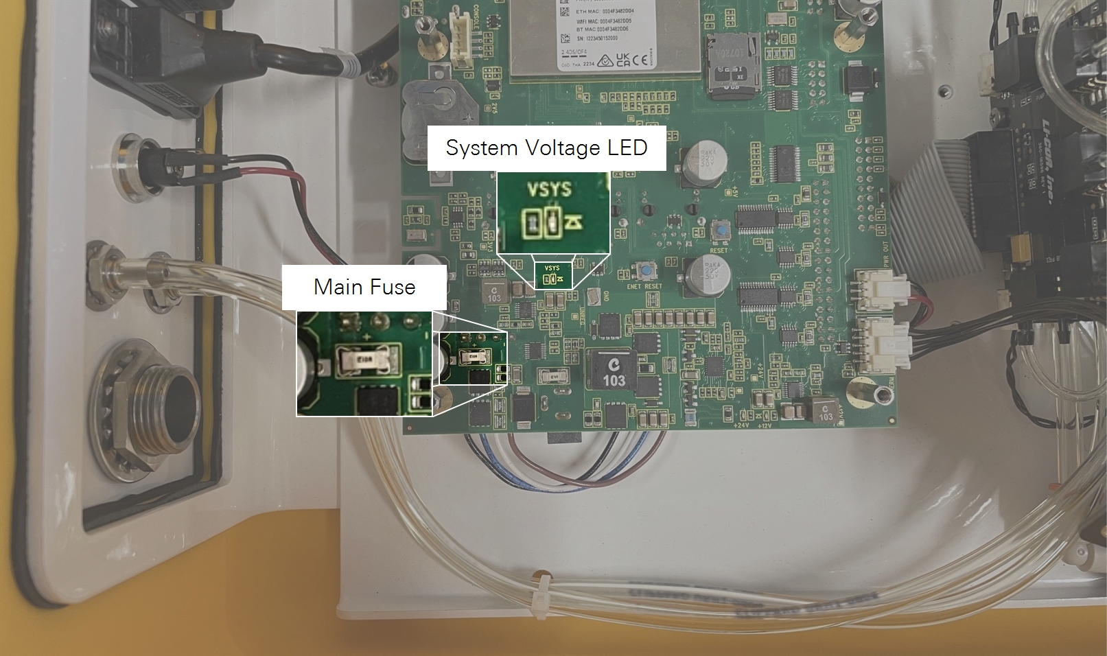
If you are providing power to the LI-8250 but the main power LED is OFF, remove the black cover inside the LI-8250 and inspect circuit board around the fuse. If the circuit board shows evidence of excessive heat (discolored, burned appearance, bubbled coatings, etc.) the board may be damaged. Contact LI-COR. If only the fuse is discolored, test it with a multimeter. If it is open, the meter will show infinite resistance. An open fuse means that there is a problem to solve - and you should solve it before replacing the fuse. See System will not power on or powers on incompletely for more information.
To replace the fuse:
-
Remove the black cover inside the LI-8250 and inspect the fuse.
If the fuse is discolored, it is probably open. Test it with a multimeter. If it is good, you'll see little or no resistance (0). If it is open, you'll see infinite resistance (1). If the fuse is good but you still have the power supply problem, it is likely that another cable or component has a short.
-
Use a pliers to pull the fuse out of the clasps.
Do not strain the board-mounted components.
-
Install a new fuse (Littelfuse SMT 10A Fast Blow, 125VAC/DC).
Replacement fuses can be purchased from online suppliers. Do not use any other fuse other than the specified fuse.