Measuring gas fluxes in a flask system
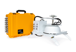
The LI-8250 Multiplexer can be used to measure gas fluxes from discrete samples in flasks, such as soil samples, fruits, or small animals with the Flask Sampling Kit (8250-660). See Flask sampling kit for a list of components included with the kit.
The Flask Sampling Kit includes a thermistor input module (9982-079) and a purge pump (9982-077). The thermistor input module allows thermistors to be attached directly to the LI-8250 Multiplexer or an 8250-01 Extension Manifold to measure air temperature inside the flasks. The purge pump serves to continuously flush the flasks with ambient (or user-conditioned) air between observations, providing a pneumatic analog to an actuated chamber.
The purge pump connects directly to the manifold inside the LI-8250 or 8250-01 Extension Manifold, providing flow. It uses the normally open side of the valve manifold as a vent (see Figure 5‑1). The unpowered valves connect the normally open channel of each manifold to the pneumatic connections on the side of the instrument, such that the flow from the purge pump is divided over all inactive ports and isolated from the active port.
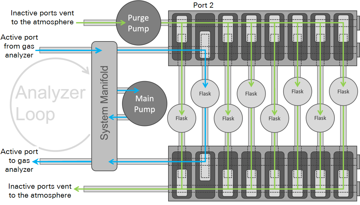
Figure 5‑2 shows what happens to flow and gas concentrations for a single flask over the course of multiple sampling sequences. When the sequence is inactive and no observations are being made on any port (e.g., between the dashed and solid black vertical lines), the total purge flow is divided over all eight ports.
Once the sequence starts (solid black vertical line) and an observation is being made on one port, the purge flow increases slightly as it is now only being divided over seven of the eight ports. In both cases, the flask is in an open loop and the concentration inside the flask is relatively constant and relatively close to the concentration of the purge air.
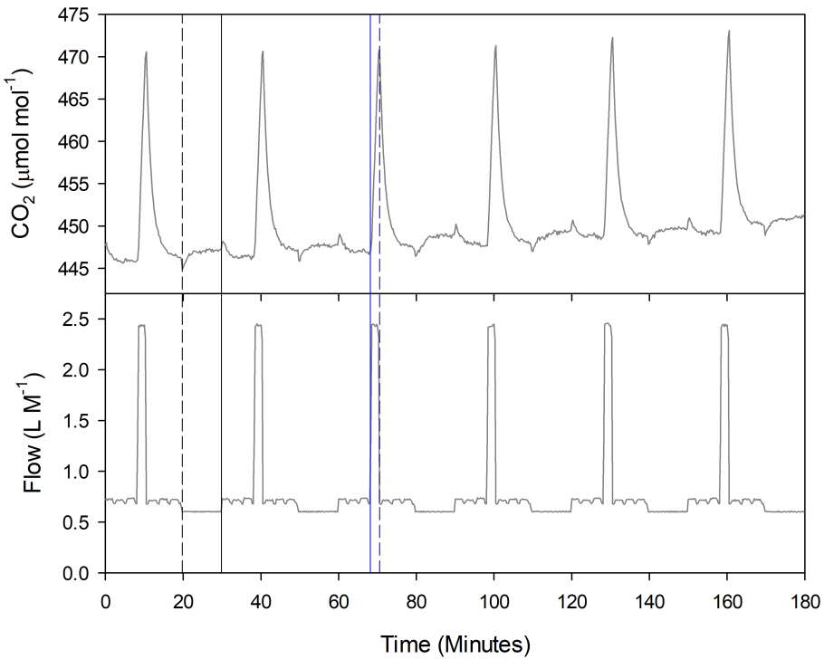
When the flask is being sampled (e.g., between the solid and dashed blue vertical lines), flow increases significantly as the flask is now the active port. At this point, the flask is in a closed loop with the measurement system. The concentration over time will change proportional to the flux. In the example shown in Figure 5‑2, the sample is evolving CO2 and CO2 concentration increases during the observation.
When the observation ends (dashed blue vertical line), the flask is purged and the concentration returns to the pre-observation levels. Note that the concentration does not instantly return to the pre-observation level. There is some wash out period primarily governed by the flask headspace volume and the purge flow rate. If perfect mixing in the flask is assumed, this washout time can be described by a time constant, τ:
5‑1

Where Vh is the headspace volume and Uv is the volumetric flow rate while purging, both with matching volume units. One τ is the time it takes to achieve ~ 63% of the concentration change. For a well-mixed headspace volume, at least three times τ is required to return to the pre-observation state. For the example data in Figure 5‑2, the headspace volume was approximately 1.6 L and the purge flow after the observation was approximately 0.7 L M-1, suggesting that it should take at least 6.8 minutes for the headspace to return to the pre-observation concentration, which fits the observed data well.
Because a flask needs to return to pre-observation conditions before another observation can be made, this time determines the minimum time between repeat observations on a flask. Depending on the nature of the sample material in the flask, some additional time may be required to allow the sample material to re-equilibrate with the headspace.
Flask design considerations
The LI-8250 uses a closed transient method for flux measurements. A fixed volume of air is circulated between the flask and gas analyzer(s). As the sample interacts with the air in this volume, gas concentrations change proportionally to the flux into or out of the sample and the volume. In a closed system, the flux velocity for a particular gas species is given by:

Where f is the flux velocity in mol s-1, P is pressure in Pa, Vs is system volume in m3, R is the ideal gas constant (~8.314 Pa m3 k-1 mol-1), and T is temperature in K. dc'/dt is the rate of change in the dry mixing ratio of the gas species of interest in mol mol-1 s-1.
Flux velocity is standardized by the sample surface area (s in m2) or the sample mass (g in kg), to yield an area-based flux (Fs) in mol m-2 s-1 or a mass-based flux (Fg) in mol kg-1 s-1:
5‑3

5‑4

Flask volume
Volume, or particularly the volume-to-unit standardization ratio (V:US), should be considered carefully in the context of expected flux rates when constructing a flask. As the volume increases for a given unit standardization and a given flux, the observed dc'/dt will decrease. With a very large flask relative to a very small flux, it is quite possible to drive dc'/dt well below the peak-to-peak noise for the analyzer used to make concentration measurements. In this case, long observation times will be required to make a measurement and uncertainty in the final computed flux will be high.
A simple sensitivity analysis using equation 5‑2 should be done to optimize the V:US, based on expected minimum and maximum fluxes and the precision of the gas analyzer. The goal is to ensure that for the selected flask volume and expected sample area or mass, dc'/dt for the minimum expected flux is sufficiently large relative to the analyzer’s peak-to-peak noise and that the headspace concentration at the end of the observation for the largest expected flux is below the analyzer’s maximum detection limit.
Air mixing
Volume (and flask shape to some degree) is also important for turbulent mixing within the headspace. A measurement inherently assumes that the gas sample pulled from the headspace and routed through the LI-8250 Multiplexer to the gas analyzer, is representative of the conditions in the flask at the moment the sample is pulled. If the headspace volume is well mixed, this assumption is valid. The observed gas concentration will change predictably as a function of the sample flux rate.
If mixing is poor, the observed gas concentration will change independently of the sample flux. These may appear as oscillations or sudden steps in the observed gas concentration during the observation. Or they may simply cause erroneous measurements that represent the combined effects of the sample flux and diffusion into or out of pockets of air trapped in the headspace that are at a different concentration than the bulk air.
In general, conditions are favorable for mixing when the headspace is turbulent and few flow obstructions are present in the flask. When flow from the LI-8250 Multiplexer drives turbulence in the headspace, smaller headspace volumes are more favorable for mixing. For larger or more irregularly shaped flasks, it may be necessary to include fans inside the headspace to aid in mixing.
Analyzer loop carryover
Due to the flow scheme of the LI-8250 (see Figure 5‑1), a small volume of gas in the analyzer loop is carried between measurements. In both datasets in Figure 5‑3, the carryover is evident by the small concentration step change at Elapsed Time zero. The measured concentration before this point is dominated by the gas already in the analyzer loop. After Elapsed Time zero, the measured concentration reflects what is happening in the flask. This carryover has two practical implications for measurements in the system:
- Observed gas concentrations at the very start of an observation do not necessarily represent initial headspace concentrations in the flask.
- Gas from a previous observation is carried into the current observation.
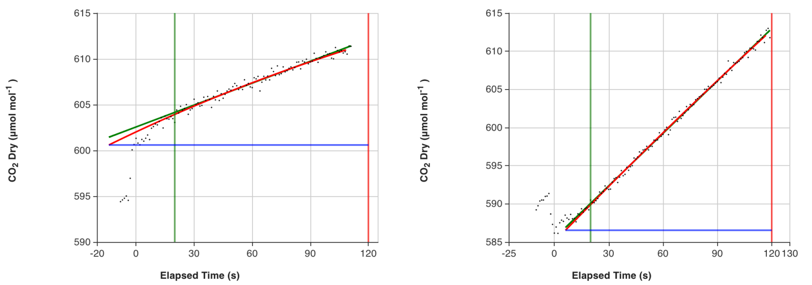
The LI-8250 Multiplexer fits an exponential model to derive the flux. For fluxes where there is strong feedback with changes along the diffusion gradient, this model better estimates the real flux before chamber closure disturbed the diffusion gradient. The exponential model relies on measurement of ambient concentration prior to chamber closure. This is the concentration the flux is regressed to.
In a flask system, the inherent carryover means the starting concentration does not necessarily represent the initial headspace concentration in the flask. Consequently, a sudden change is often observed some time into the observation, as shown in Figure 5‑3. If this sudden change is not accounted for, it will impact the initial gas concentration estimate and, subsequently, the derived exponential flux. Analyzer loop carryover can be accounted for by configuring a pre-purge time (see Configuring flask measurements).
For flasks, the pre-purge time is not a purging or flushing period as it is for traditional chambers. Instead, it delays the point the system considers time zero and when the initial concentration is taken (blue lines in Figure 5‑3). In Figure 5‑3, data was collected using a 10-second pre-purge. In both cases, the result is an initial concentration estimate that fits well with the subsequent data. To determine the pre-purge time, we suggest making some preliminary measurements using your specific setup before collecting any meaningful data.
Note: The pre-purge is not adjustable in SoilFluxPro™ Software like the other fit parameters are, making it difficult to recover the correct exponential flux from data collected using an inappropriate pre-purge. SoilFluxPro fits both an exponential and linear model (red and green fit lines respectively of Figure 5‑3) and provides a flux estimate from both fits. The linear model is mostly unaffected by where time zero is set (pre-purge time). Meaning that the linear flux can often be used to get a reasonable flux estimate for data collected with an inappropriate pre-purge.
For studies where mixing of gas between flasks is undesirable, a port can be dedicated as an analyzer loop purge. This will flush the analyzer loop with ambient (or user-conditioned) air between observations and will greatly reduce or eliminate flask-to-flask gas mixing. However, the air in the analyzer loop from the purge will still be carried over to the next flask observation.
Hardware requirements
Both the purge pump and thermistor input module are required for flask measurements, and both must be installed in any instrument (LI-8250 Multiplexer or 8250-01 Extension Manifold) that connects to a flask. For example, if you have a system with a multiplexer and two extension manifolds and you would like to connect flasks to each, three flask kits are needed (one for each instrument). If, for example, you will not be connecting any flasks to the multiplexer, only two flask kits are needed (one per extension manifold).
Because the current draw for a purge pump in an extension manifold exceeds what the multiplexer can supply, each extension manifold used for flask measurements must be powered via the alternate power input. You will need one indoor AC to DC power supply (part number 8250-772) for each extension manifold with a flask kit. You can power the multiplexer using the indoor AC to DC power supply or the outdoor AC to DC power supply (part number 8250-770).
Flask measurements require at least one temperature measurement. The temperature measurement must be made using a thermistor connected to the same instrument as the flask. Up to eight thermistors can be connected to each thermistor input module, and a thermistor can be mapped to one or more flasks.
In our example system above, if flasks are connected to the multiplexer and both extension manifolds, a minimum of three thermistors are required (one per instrument). If each flask had a thermistor, there could be up to 22 thermistors (eight on each extension manifold and six on the multiplexer). Where temperatures are relatively uniform across the system, such as in a temperature-controlled growth cabinet, one thermistor per instrument may be sufficient. Where temperatures differ across the system, multiple thermistors will be required.
Preassembled, weatherized thermistors are available from LI-COR (part number 9982-081). These thermistors are potted into a stainless-steel housing, fit to a sealed cable gland, and include a 15 m shielded cable. The cable gland mounts through a 12.5 mm diameter hole in materials up to 3 mm thick and is held in place by a nylon hex nut. Alternatively, the gland may be threaded directly into a PG 7 (steel conduit threading per DIN 40430) threaded hole.
Note: For a proper seal, the gland shoulder must compress against the mounting surface, where the gasket is located.
User-provided thermistors can also be used in the system. The thermistor input module is optimized for 10 kOhms at 25 °C nominal NTC thermistors. Steinhart-Hart coefficients for the user-provided thermistor must be known and set in the instrument configuration. No provision is included in the flask kit to seal a user-provided thermistor into a flask.
Connecting tubes and thermistors to flasks
Each Flask Sampling kit includes fittings and 30 m of Bev-A-Line® tubing to connect the user flask to the instrument (see Figure 5‑4). You may cut the tubing to your desired length, and additional tubing can be ordered in 15 m rolls using part number 8150-250.
The tubing connects to fittings installed on the flask and to the instrument using barbed quick-connect fittings (part numbers: 300-07124 [male] and 300-07125 [female]). These fittings have a barb on one side that you press into the end of the tubing. Ensure you have cut the tubing end square and cleanly before inserting the barb. Install one male and one female barbed quick-connect fitting per tube.
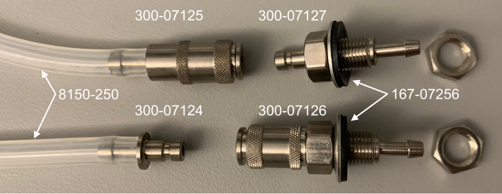
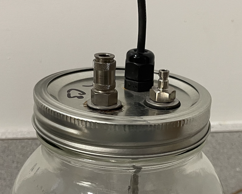
Bulkhead quick-connect fittings (part numbers: 300-07126 [female] and 300-07127 [male]) provide a connection at the flask. These fittings mount through materials up to 4.5 mm thick (accounting for seal thickness) via an 8.5 mm diameter through-hole. Seal washers (part number 167-07256) provide a gas-tight seal. Slide the washer over the threads of the fitting with the rubber side away from the quick-connect end. Install one male and one female bulkhead quick-connect fitting per flask using an 11 mm wrench for the fittings and accompanying nuts.
Note: To properly seal, the rubber side of the washer must compress against the mounting surface.
Installing the flask sampling kit
The following instructions will guide you through installing the Flask Sampling Kit into an LI-8250 Multiplexer or 8250-01 Extension Manifold.
Caution: Before installing the Flask Sampling Kit, power down your system and disconnect all power inputs. Keep the system powered off until you have installed all flask hardware.
Powering the LI-8250 and 8250-01 Extension Manifolds
Use one indoor AC-to-DC power supply (part number 8250-772) to power the LI-8250 and each 8250-01 Extension Manifold that is used for flask measurements.
- Use a pair of 24-mm wrenches to remove the metal seal from the analyzer connection panel (multiplexer) or multiplexer connection panel (extension manifold).
- With this plug removed, tubing and cables can pass through the panel and the case can be closed.
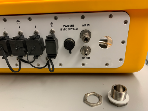
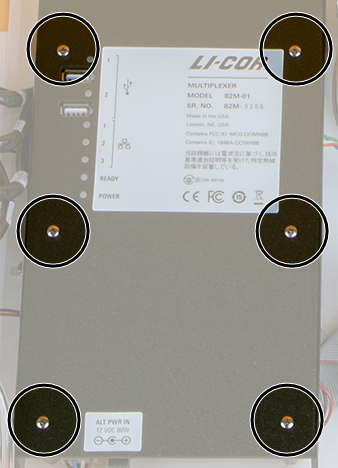
- If you are using the indoor AC-to-DC power supply (part number 8250-772), pass its connector through the cable port and connect it to the ALT PWR IN barrel jack on the interior panel (see Figure 2‑5).
- Be sure the power supply and multiplexer are powered off (not connected to power) when making this connection.
-
Repeat this for each Extension Manifold that hosts flasks in the system.
Each Extension Manifold must be powered individually in this configuration.
Install the purge pump
One purge pump must be installed in each LI-8250 Multiplexer and 8250-01 Extension Manifold that hosts flasks.
Caution: Do not touch an exposed circuit board, as electrostatic discharge can damage it.
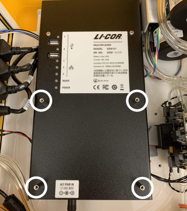
- Remove the six PH1 Phillips screws from the interior panel cover and lift it off.
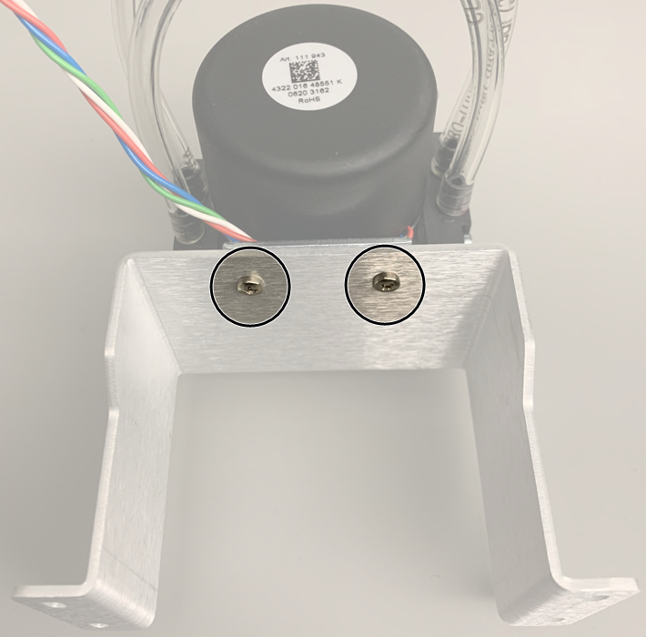
- Attach the mounting bracket (part number 9882-042) to the purge pump using two Phillips screws from the kit (part number 150-14477).
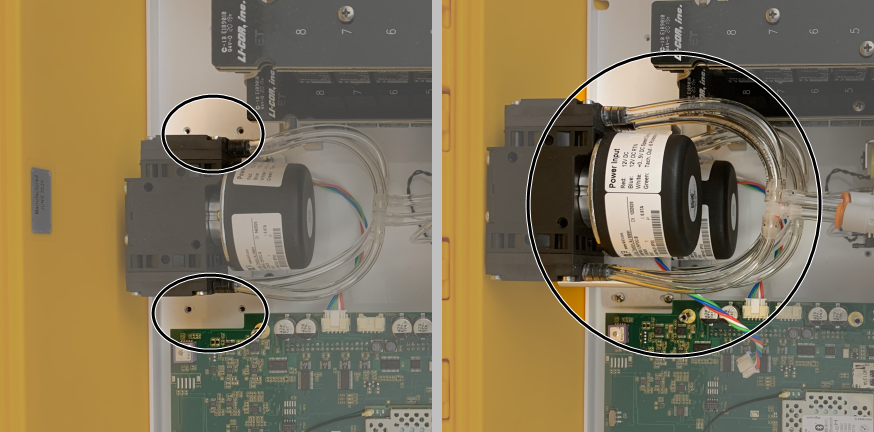
- Position the pump and bracket assembly over the main pump as shown and mount it to the base plate using four Phillips screws from the kit (part number 150-14477).
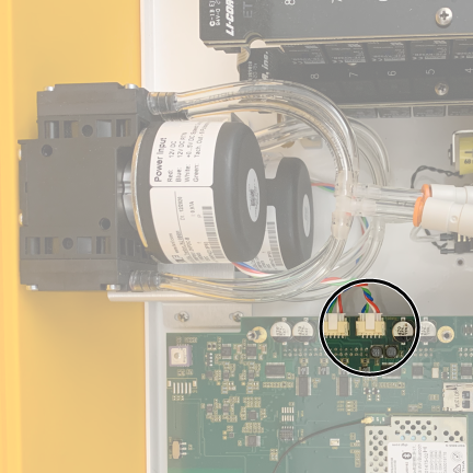
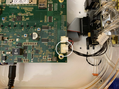
- Connect the power cable from the purge pump to the main board as shown.
- The purge pump connects to the connector closest to the main pump connector.
- Remove the plugs from the upper and lower valve manifold using an 8 mm wrench or a flat-head screwdriver.
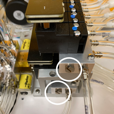
-
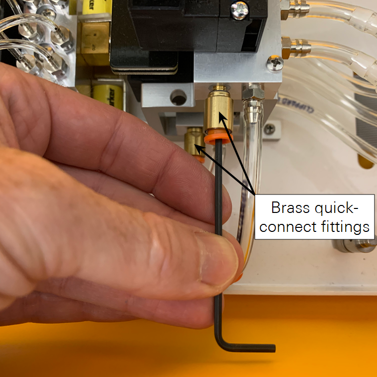
Install two brass quick-connect fittings (part number 300-08251) the openings of the upper and lower valve manifolds.
To install the fittings, use the hex key to start and then finish tightening the fitting by hand to compress the gasket against the manifold.
- Connect the tubing with the T-fitting from the purge pump to the brass quick-connect fitting on the lower valve manifold.
- Push the tubing into the fitting and pull back slightly to seat it in place.
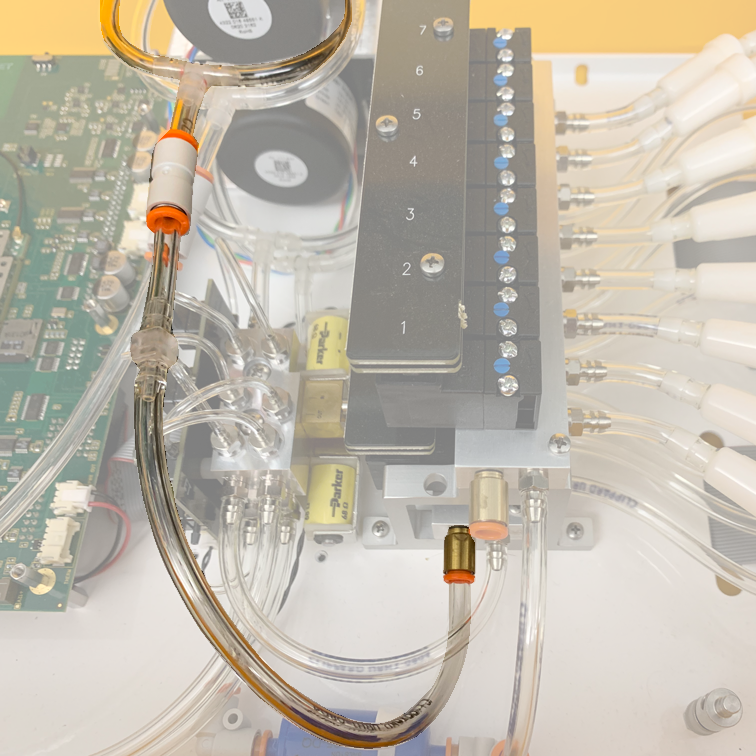
- Route the tubing with the filter from the purge pump through the cable port of the analyzer connection panel (multiplexer) or multiplexer connection panel (extension manifold).
- If desired, route a length of tubing from the upper valve manifold through the cable port of the analyzer connection panel (multiplexer) or multiplexer connection panel (extension manifold). This is recommended if moist air will be returned from the flasks.
Install the thermistor input module
Caution: When not installed, the module is sensitive to electrostatic discharge (ESD). Handle it only by the edges and after touching a ground connection to prevent damage.
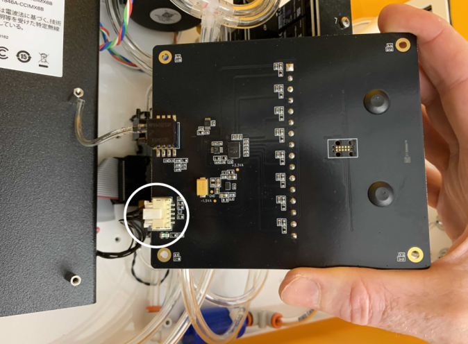
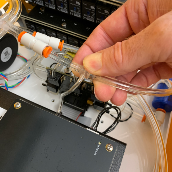
- Connect the cable for the thermistor input module to the main board.
- Align the keys on the white connectors and press in until they are seated. It does not matter which end you connect.
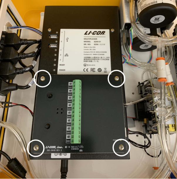
- Replace the cover using two Phillips-head screws in the holes furthest from the ALT PWR IN jack (top of the cover).
- Install standoffs (part number 161-18848) in the four remaining holes. Be careful not to overtighten the screws or standoffs.
- Connect the other end of the cable for the thermistor input module to the thermistor input module.
- Install the thermistor input module onto the standoffs using the four remaining cover screws you removed previously.
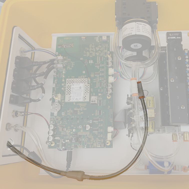
- Connect the pressure sensor tubing from the thermistor input module to the T-fitting on the purge pump tubing.
- The T-fitting is on the tubing that connects to the brass quick-connect fitting on the lower valve manifold.
- Connect the air tubing quick-connect fittings to the flasks and the chamber connection panel.
- There are two connections per port and flask.
Connecting thermistors
Thermistor channels and flask port numbers do not have to match. However, the thermistor and flask must be connected to the same instrument (i.e., LI-8250 Multiplexer or 8250-01 Extension Manifold).
- Pass the thermistor cable through the cable port.
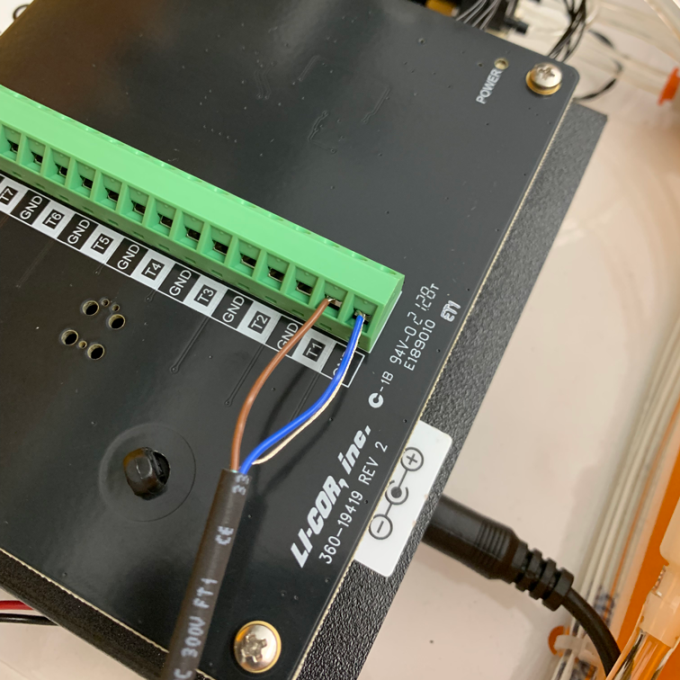
- If you are using a LI-COR thermistor (part number 9982-081), connect the brown wire to a numbered input terminal (T1 through T8) on the green terminal strip at the center of the thermistor input module.
- Twist the ends of the blue wire and the uninsulated shield wire together. Connect these to the ground (GND) terminal adjoining the numbered input terminal you selected.
- Secure the thermistor cable to one of the strain relief posts on the thermistor input module using a zip tie if desired.
- Repeat steps 1-3 for all thermistors.
Finish the flow configuration
- If you will be using a port to purge the analyzer loop, choose which port you will use now.
- Connect a length of tubing to the OUT port of that port. The length should be equivalent to the total tubing length (to and from) for one flask. This ensures that the back pressure on this port is comparable to the others and prevents excess purge flow when not being sampled.
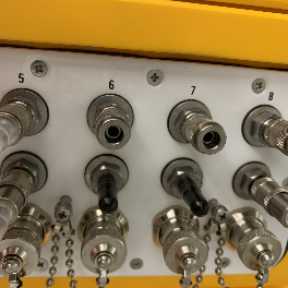
- Cap the OUT port of any ports not used for a flask or purging.
- Place a black vinyl cap (part number 620-08298) over the quick-connect fitting of the OUT ports.
Power on the system
-
Connect all power supplies to mains power - the system will turn on.
Use one indoor AC-to-DC power supply (part number 8250-772) to power the LI-8250 and each 8250-01 Extension Manifold that is used for flask measurements.
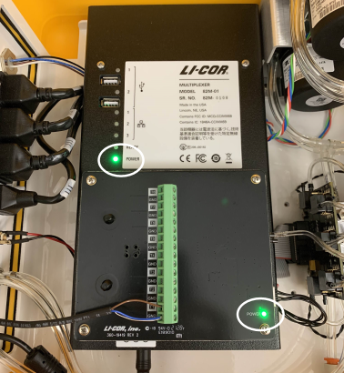
- Verify all POWER lights illuminate for all instruments, including the thermistor input module.
Configuring flask measurements
For the most part, configuring a flask system is identical to configuring a LI-COR long-term chamber. Where flasks differ is that they use the Flask block and require different inputs to this block.
When you first open the Configuration page, you will see two empty root blocks: the LI-8250 Multiplexer block and the Sampling Sequence block. This section will cover the details relevant to configuring a flask system for measurements.
Note: When configuring a system with multiple chambers and extension manifolds, you can copy and paste or duplicate blocks to speed things up.
-
Add a purge pump block.
Under Soil Chambers > Custom Chambers add the Purge Pump block. Add one to the root block of each LI-8250 Multiplexer and 8250-01 Extension Manifold that hosts a flask.
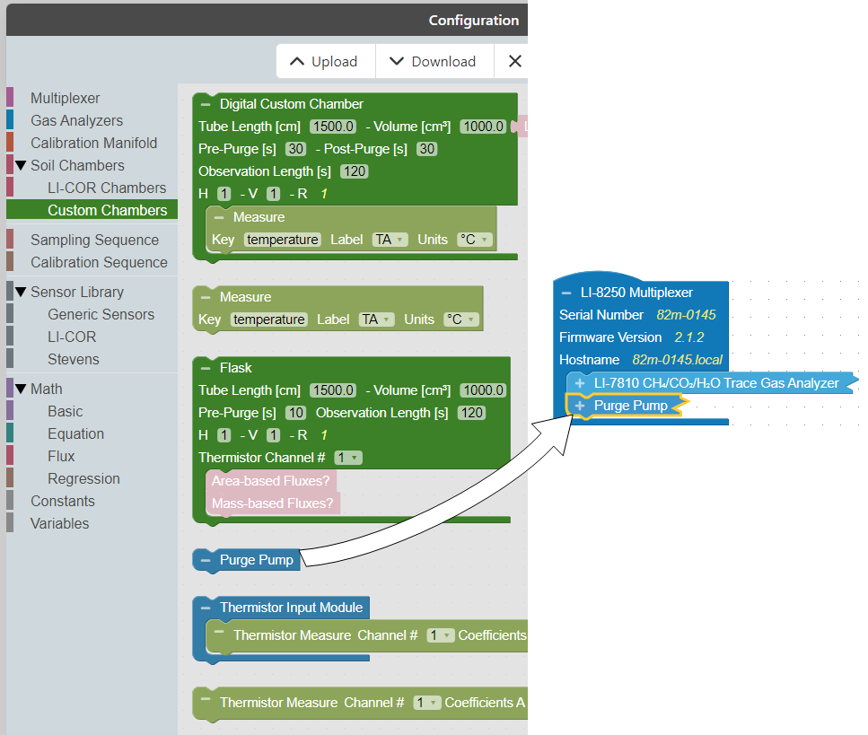
This block specifies that the instrument should enable the purge pump. When this block is present, the purge pump runs by default.
-
Add a block for the thermistor input module.
A Thermistor Input Module block is accepted by the root block of the LI-8250 Multiplexer and 8250-01 Extension Manifold) that hosts a flask. Under Soil Chambers > Custom Chambers, select the Thermistor Input Module block and add it to the multiplexer or extension manifold block.
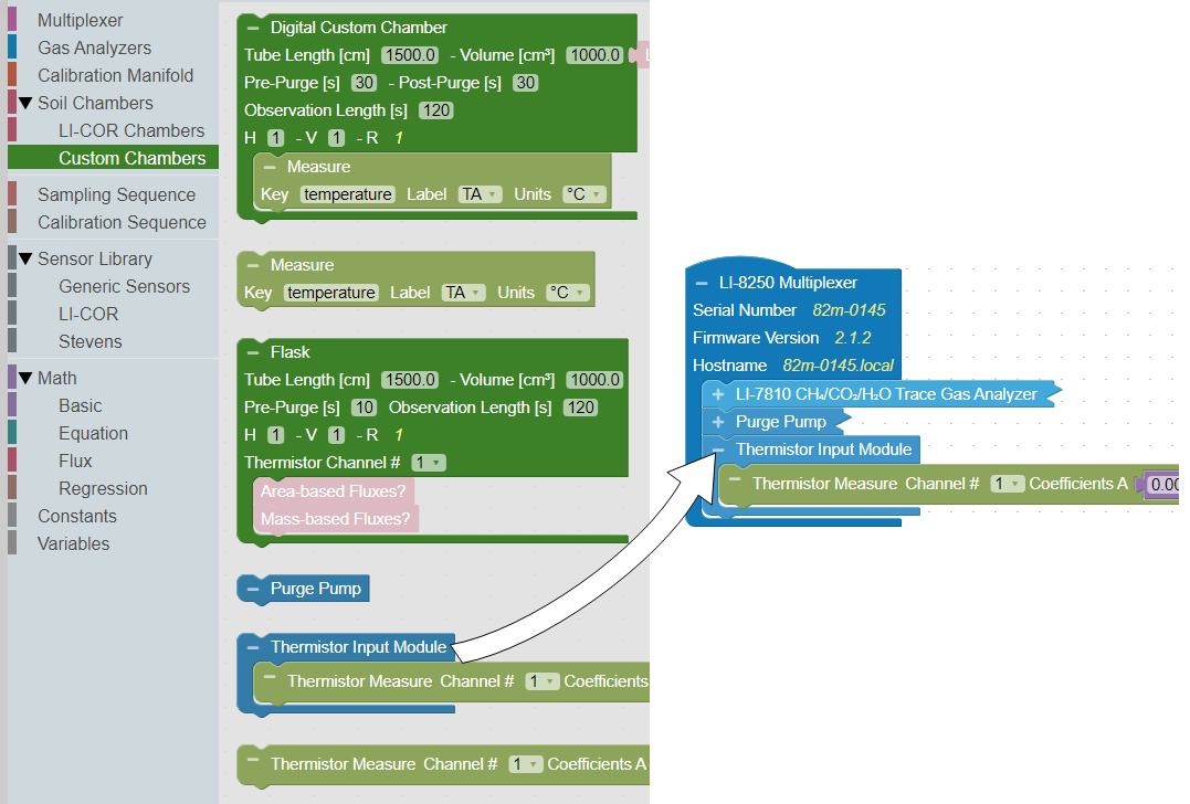
This block allows you to add up to eight thermistors to each instrument.
-
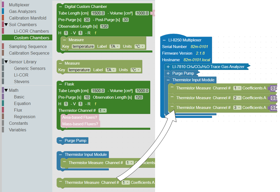
Add another thermistor measurement block (optional).
By default, each Thermistor Input Module block includes a Thermistor Measure block. If you have more than one thermistor on an instrument, you will need to add a Thermistor Measure block for each additional thermistor.
Expand the Soil Chambers menu in the Toolbox and select Custom Chambers. Then click and drag the Thermistor Measure block under the Thermistor Input Module block where it is to be added. Then set the Channel to the numbered input on the module where the thermistor is connected.
-
Optionally, customize coefficients for custom sensors.
If you are using the LI-COR thermistor assembly, the A, B, and C parameters can be left at the default Steinhart-Hart coefficients for these sensors. If you are using a user-provided thermistor, set the values to match the coefficients of that sensor. You can do this for each block individually, or you can create a set of Constants blocks, as shown.

-
Add a port.
Each extension manifold and flask requires a port block that specifies the port that the device is connected to. Select Multiplexer from, then click and drag a Port # block under the LI-8250 Multiplexer or 8250-01 Extension Manifold block.
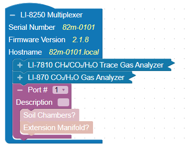
You can assign a port number or the user interface will automatically assign a port number as these blocks are added. You can also provide a description of the devices on that port that will appear in the data file.
-
Add a flask.
After you have added a port to the LI-8250 Multiplexer or 8250-01 Extension Manifold block, you can add a flask to that port. To add a flask block, expand the Soil Chambers menu in the Toolbox and select Custom Chambers. Then click and drag the Flask block under the Port # block. Repeat this for each flask.
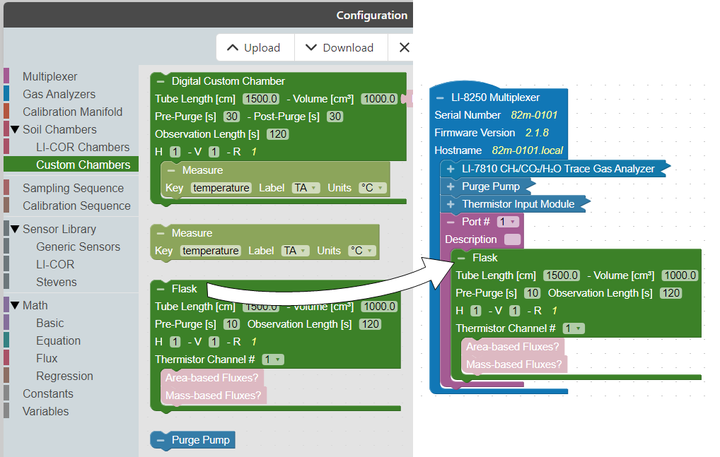
-
Set the Tube Length and flask Volume. The Tube Length is the one-way length of the tubing from the instrument to the flask. For example, if your flask is connected by 1.5 meters of tubing to the flask and another 1.5 meters of tubing returning from the flask, enter the tube length of 150 cm.
Set the Thermistor Channel # to the thermistor this flask will use for flux calculations. This could be a thermistor installed in the flask or outside of it, and multiple flasks may reference the same thermistor.
Then, set the Observation Length and Pre-Purge according to your needs. Ten seconds is a good place to start for a pre-purge. Additional details about the pre-purge and how it can influence fluxes can be found in Analyzer loop carryover.
-
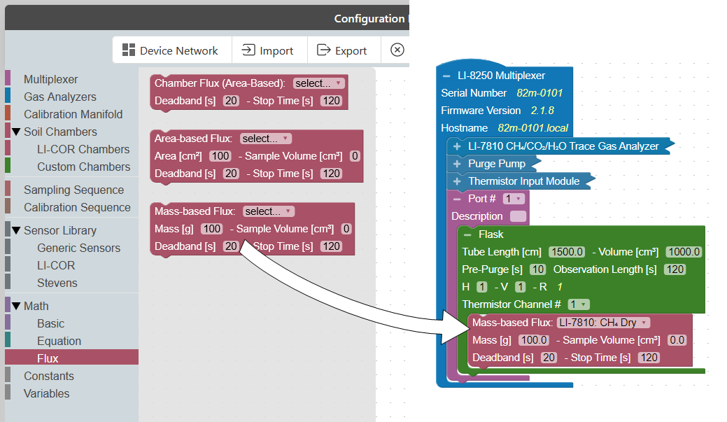
Add a flux.
Choose either Area-based Flux or Mass-based Flux. The Area-based Flux is used to specify a flux calculated on a per area basis and the Mass-based Flux is used to specify a flux calculation on a per mass basis.
To add a flux block to your custom chamber block, expand the Math menu and select Flux from the Toolbox. From the Flux drawer click and drag either the Area-based Flux block or the Mass-based Flux block under the flask you would like to add the flux to. You can have multiple Flux blocks under each flask depending on the analyzer(s) you are using and the gases you would like recorded.
Note: Only one type of flux block (area or mass) may be placed inside a Flask block. Multiple flux blocks may be placed under the Flask block to accommodate different gas species, but they must be of the same type.
Each flux block allows you to customize additional parameters required for the flux calculation. If a sample occupies some volume inside the flask, enter a Sample Volume. This value is subtracted from the system volume to provide a more accurate total volume estimate for the flux calculation.
Note: If multiple flux blocks for different gases are included under a Flask block, the sample volume and area/mass values for all flasks must be consistent or your configuration will not Verify.
- Area-based flux: Select the gas and the source for flux calculations. Under Area, enter the sample surface area in cm2. You can also adjust the Deadband and Stop Time as needed. The Deadband and Stop Time are parts of the total Observation Length. Stop Time can be any time desired so long as it is beyond the Deadband and does not exceed the Observation Length. A good Deadband to start with is 15 to 20 seconds, but this can be adjusted in post-processing using SoilFluxPro Software.
- Mass-based flux: Select the gas and the source for flux calculations. Under Mass, enter the sample mass in grams. Under Sample Volume, enter the calculated volume of the sample in cm3. This is used to correct the total volume for sample displacement. You can also adjust the Deadband and Stop Time as needed; both contribute to the total Observation Length. Stop Time can be any time desired so long as it is beyond the Deadband and does not exceed the Observation Length. A good Deadband to start with is 15 to 20 seconds, but this can be adjusted later in SoilFluxPro Software.
Note: One Flux block is required for each gas flux computed. Without a Flux block, no flux will be calculated for that gas. If a Flux block was not added for a gas, a flux can still be calculated later using SoilFluxPro Software.
-
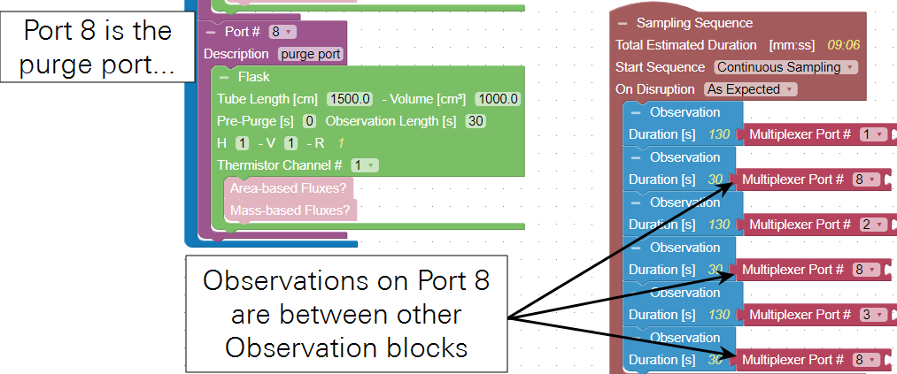
Add a purge port (optional).
As mentioned in Analyzer loop carryover, a dedicated purge port can be added to avoid air mixing between flasks. A Flask block still needs to be added to that port (even though there is no flask physically connected), but a flux block is not necessary. The Observation Length should be the duration of the purging event, and pre-purge can be set to zero. Tube length, volume, and thermistor channel do not matter. In the Sampling Sequence, the purge port can be interspersed between each flask.
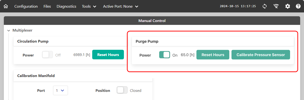
Calibrating the purge pump
Before using the system for the first time, you will need to calibrate the pressure sensor in the purge pump. To open the manual controls, first connect to the LI-8250 Multiplexer interface. Then expand the Tools drop-down and click Manual Control.
Each instrument with a purge pump installed will have a Purge Pump panel. Click Calibrate Pressure Sensor for each purge pump.
Note: For each 8250-01 Extension Manifold with a purge pump, you will need to expand the tool panel to access its Purge Pump panel.
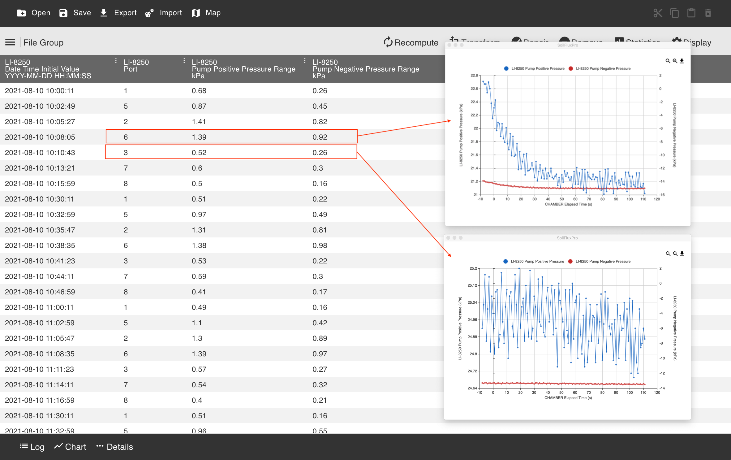
Finding leaks
Flask measurements require that the system be leak-free. This means that there are no volumetric gains or losses independent of the gas flux. You can use the built-in leak test to identify leaks between the multiplexer, extension manifold(s), and all tubing, but this test will not determine if a flask leaks. Large flask leaks may be evident in the time series of gas concentrations. Small leaks may be less obvious in the concentrations but may still be detectable in the positive and negative pressures reported for the main LI-8250 Multiplexer pump.
If these pressures consistently vary by a significant amount (greater than 1 kPa) over each observation, there may be a leak in the flask. When used with an 8250-01 Extension Manifold, these pressures may show sudden changes during an observation as the main pump adjusts flow.