Using the Power Distribution Box
LI-COR Power Distribution Boxes (PDB) are power supply junctions for sensors and analyzers in eddy covariance systems.
What's what
If you have just taken delivery of the Power Distribution Box, check the packing list to be sure you received everything that you ordered. It is shipped partially assembled and many of the components are installed in the box. Depending upon your specifications, it may include:
Unregulated power supply
Part Number 7900‑230
Provides 11 connections for powered sensors, with the power output equal to the power supplied, 10 amps maximum. Includes weather-resistant enclosure and a circuit breaker.
Regulated power supply
Part Number 7900‑231
Provides six unregulated outputs with power out equal to the power supplied (8 amps maximum) and two 12 volt outputs (2 amps maximum). Voltage is regulated by a charge controller and voltage regulator (part number 7900-127).
Note: You may wonder, why use a 12 volt regulator when most components of the system list 28 or 30 volts as the upper limit? It turns out that a 24 volt solar power supply can actually supply >31 volts under sunny very cold conditions. This could damage sensors or cause them to power off unexpectedly. The 12 volt regulator ensures that the voltage will not exceed the limits of the sensors. You may still wonder: Why not use a 12 volt solar power supply? A 12 volt supply is great unless you have a long cable run, in which case the voltage can drop beyond the lower limits of the sensors, causing them to power off. The configurations we provide should supply reliable and safe power to your system without exceeding the upper or lower limits of the system.
20 m power wire
Part Number 7900‑232
A 65 ft (20 m) 10 AWG cable in conduit. The power cable with conduit protection should be used for cable in contact with the ground.
40 m power wire
Part Number 7900‑233
A 130 ft (40 m) 12 AWG cable without conduit that connects a power distribution box at the top of a tower to a power distribution box at the bottom. Not for ground contact.
Mounting kit
Part Number 9979‑026
The enclosure mounting kit with 15 cm mounts is to attach the power distribution box to a tripod mast or tower.
In addition to those described previously, the following replacement parts may be ordered.
Inquire with LI-COR if you need a replacement part that is not on this list. Spare and replacement parts can be ordered directly from LI-COR or your local distributor.
Safety warnings
Mind the safety notes in this manual to ensure safe operation of the power distribution box and to avoid damage to equipment.

 Warning: Wear gloves and safety goggles when installing and servicing the power distribution box.
 Caution: Read the instructions of the equipment you are connecting to the power distribution box before installing the system. Save any instructions, including these, for future reference.
Caution: Use insulated tools to avoid unwanted metal-to-metal contact that may result in a shorted circuit.
Warning: Turn off the 10A breaker and disable the power supply before installing or modifying the connections. Be sure that the installation is in compliance with local ordinances and the National Electrical Code. Consult a professional electrician if needed.
Caution: Do not reverse the polarity or short circuit the poles or your equipment may be damaged. Be sure to connect the positive wires to the red terminals and negative wires to the black terminals.
To prevent damage to equipment, check your work before turning the breaker switch ON.
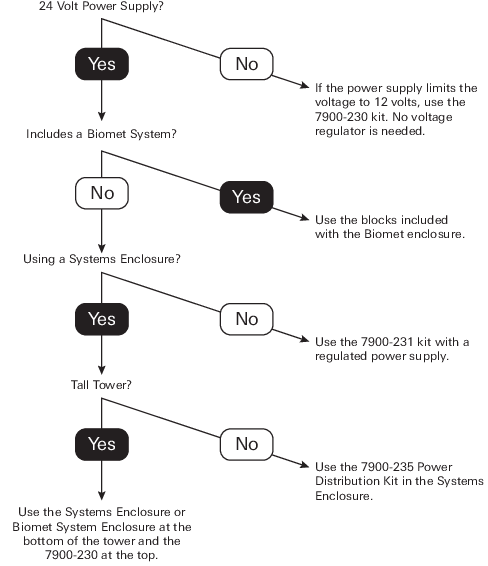
Use cases
Each configuration of the power distribution box is suited for a specific case. This section provides an overview of these scenarios.
Caution: For systems that have a 24 VDC power supply, be sure to use a voltage regulator to power all devices that have an upper voltage limit <28 VDC. See the note under Using the Power Distribution Box.
Initial setup
The following section describes how to set up the PDB. The following tools are required:
- Phillips screwdriver
- Bolt drivers or wrenches: 13 mm and 8 mm (1/2" and 5/16" SAE equivalents)
- Standard slotted screwdriver (optional, instead of 8 mm driver for mounting band clamps)
- Small standard slotted screwdriver (to install wires in terminal blocks)
- Wire trimmer/stripper (optional)
Allow about 30 minutes to install the hardware.
1. Attach the Power Cable and Strain Relief Fitting
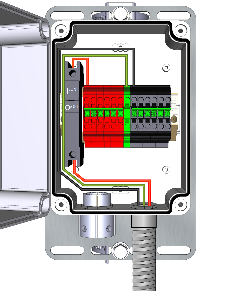
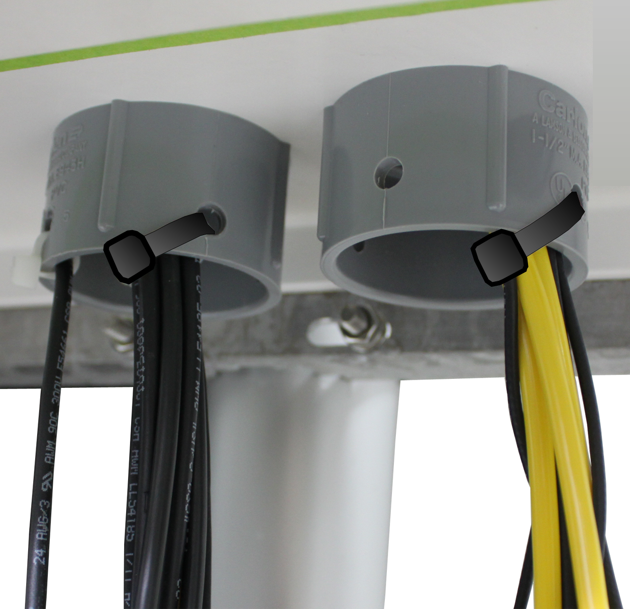
Loosen the two captive screws and open the lid. Install power cable conduit as shown below.

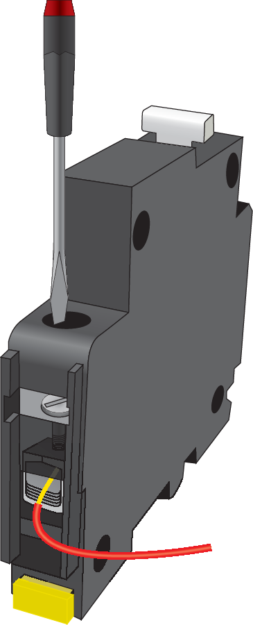
2. Connect the Power Cable Leads
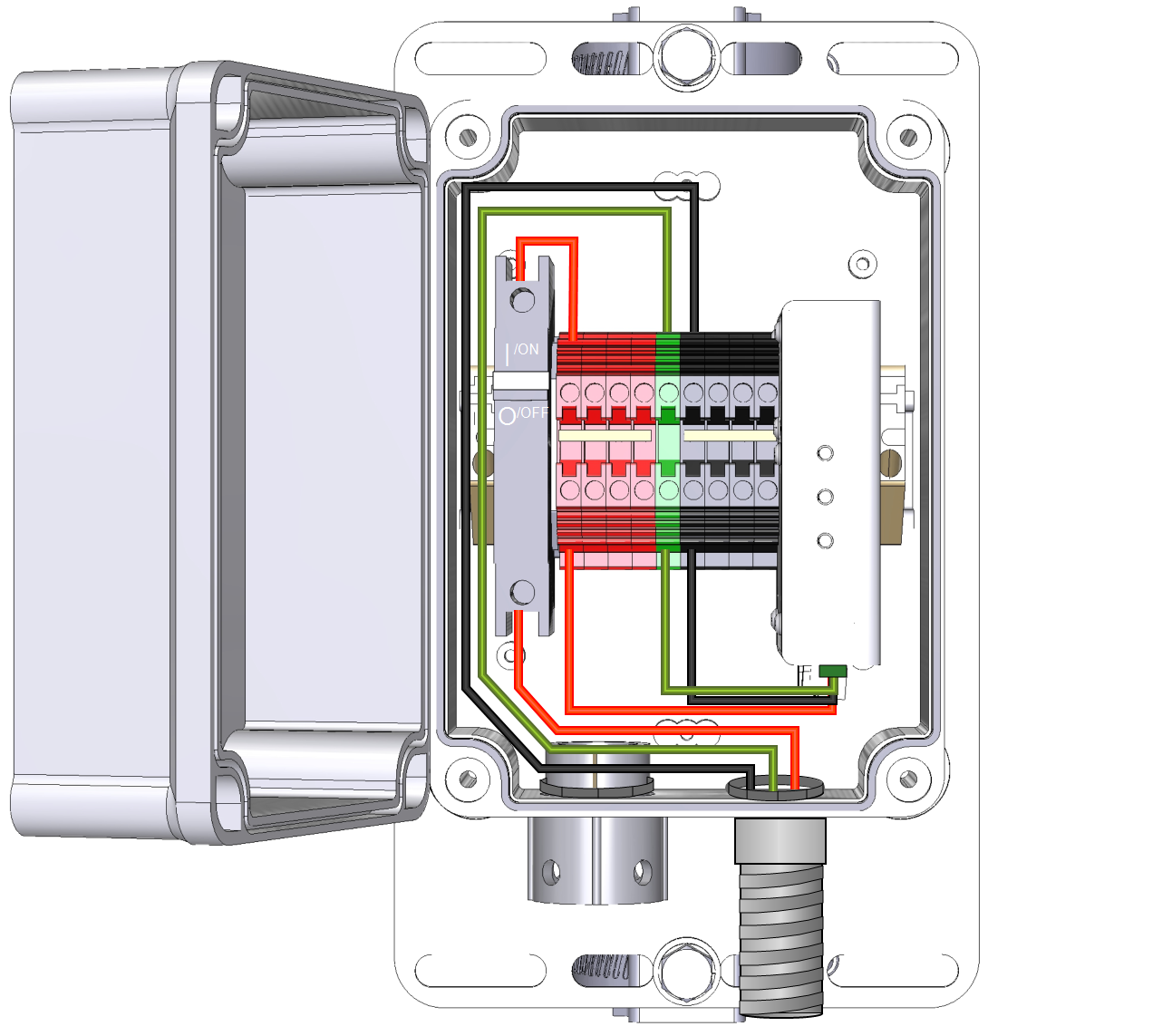
In the power supply box, connect the ground (bare) wire to the green terminal, the red wire to the bottom contact on the breaker, and the black wire to a black negative terminal.
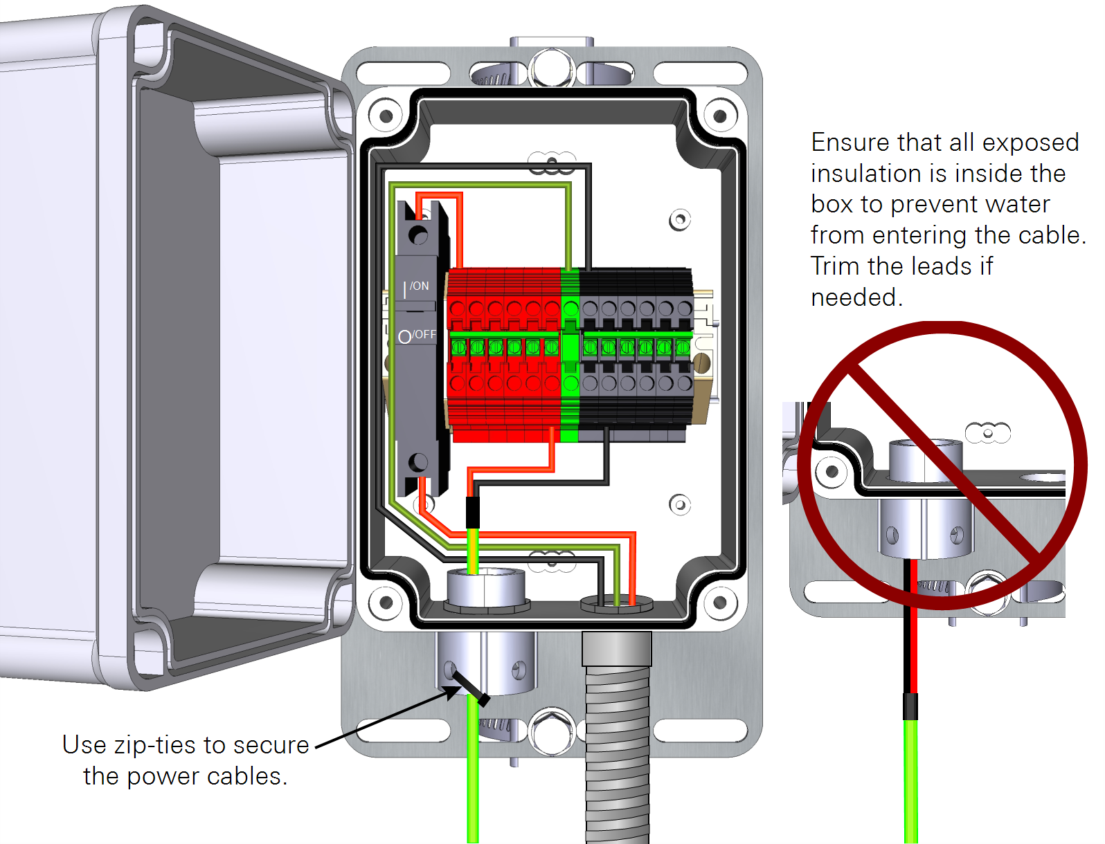
Important: Be sure that the clasp closes onto bare wire, rather than the non-conductive insulation.
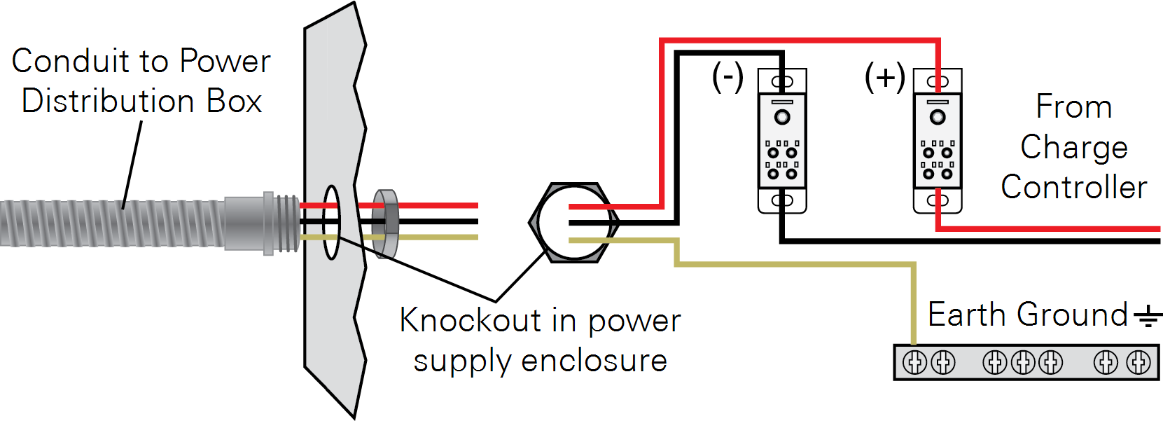
3. Connect the Power Cable to the Supply
Route the wires through a knock-out at the power supply and attach the conduit to a knock-out. At the power supply, connect the bare wire to an earth ground, the red wire to the positive load terminal, and the black wire to the negative load terminal.
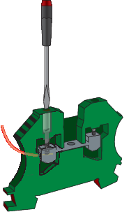
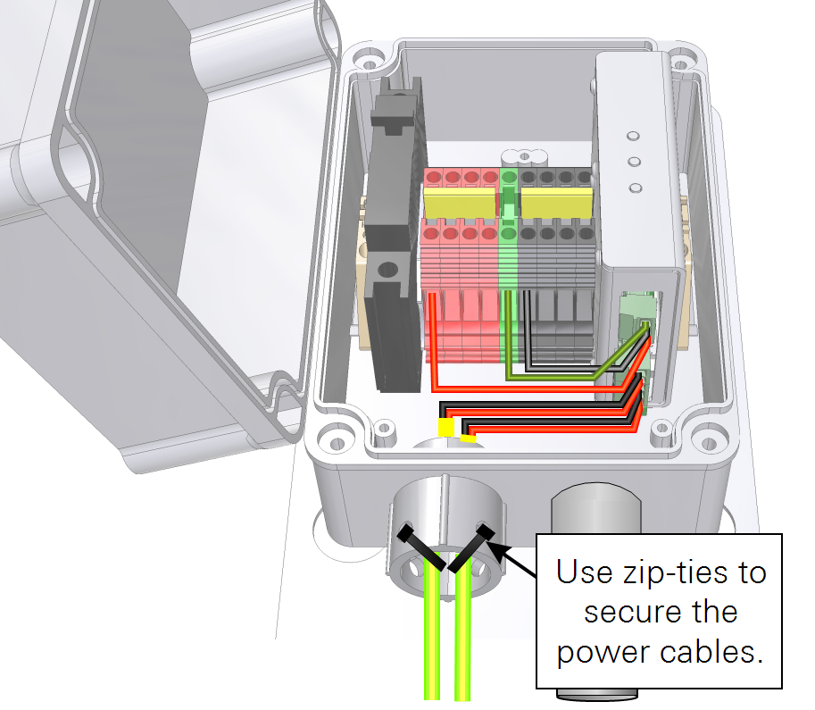
4. Install the Sensor Power Wires
Switch the breaker OFF before installing power wires or servicing the box. Route the sensor power wires through the strain relief fitting. Trim the leads to the desired length. Insert the wire into the terminal and tighten it onto the conducting part of wire, as shown in Connect the Power Cable Leads.
5. Mount the Power Distribution Box
Mount the power distribution box with the conduit and strain relief fitting on the bottom. See Mounting the box for more details.
6. Verify the Power Supply
After connecting all the power supply and distribution wires, switch the breaker to ON and verify that each sensor is powered. Secure the lid with the two captive screws. Trim a piece of metallic wool and insert it into the top of the strain relief fitting.
Using the voltage regulator
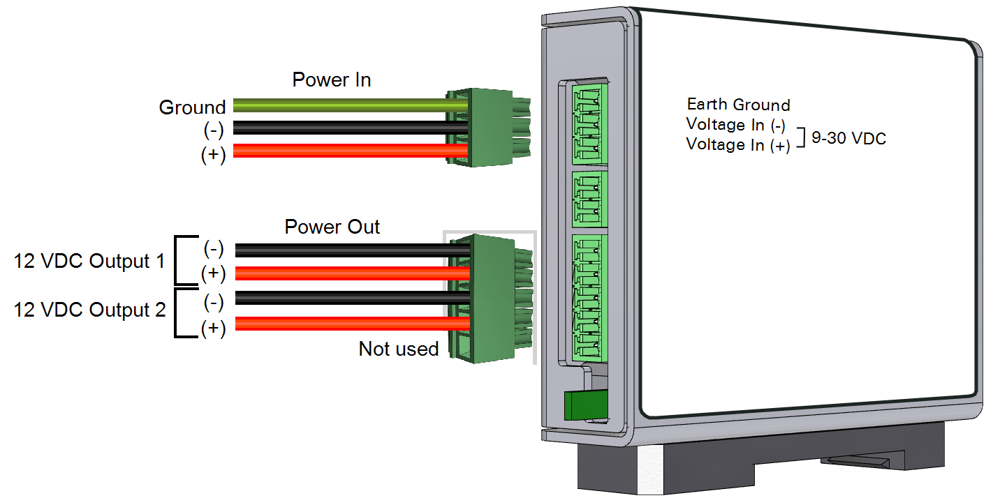
The voltage regulator (part number 7900-127) conditions the input voltage and provides two 12 VDC output power connections.
Indicator LEDs and terminals
The charge controller/ voltage regulator has 3 LEDs. The main power LED indicates that the device is powered. The ON and battery LEDs are not used in this application.

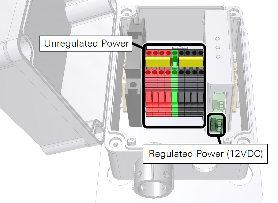
When installed in the 7900-231, the unregulated power output is from the red and black DIN terminals and the regulated output is from the charge controller (see Figure 1‑1).
Connecting sensor power wires
- Power-in ground connects to the green terminal.
- Power-in positive (+) connects to a red terminal.
- Power-in negative (-) connects to a black terminal.
The device has three terminal strip connections. The power-in and power-out connections are used in this application.
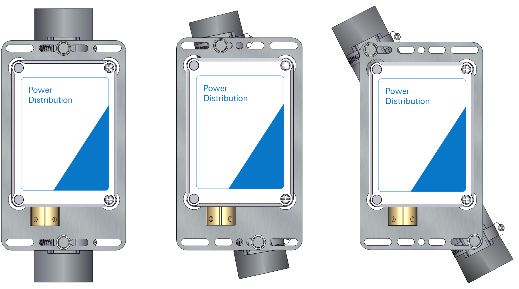
Mounting the box
The mounting kit consists of a mounting plate and two band clamps. The band clamps can be attached to a tripod mast, leg, or tower.
Important: The power distribution box should be oriented vertically with the openings facing the ground. The breaker uses a hydraulic-magnetic mechanism that require a vertical orientation. The vertical orientation also will help prevent water from entering the enclosure through the bottom opening.
| Item | Part No. | Description | |
|---|---|---|---|
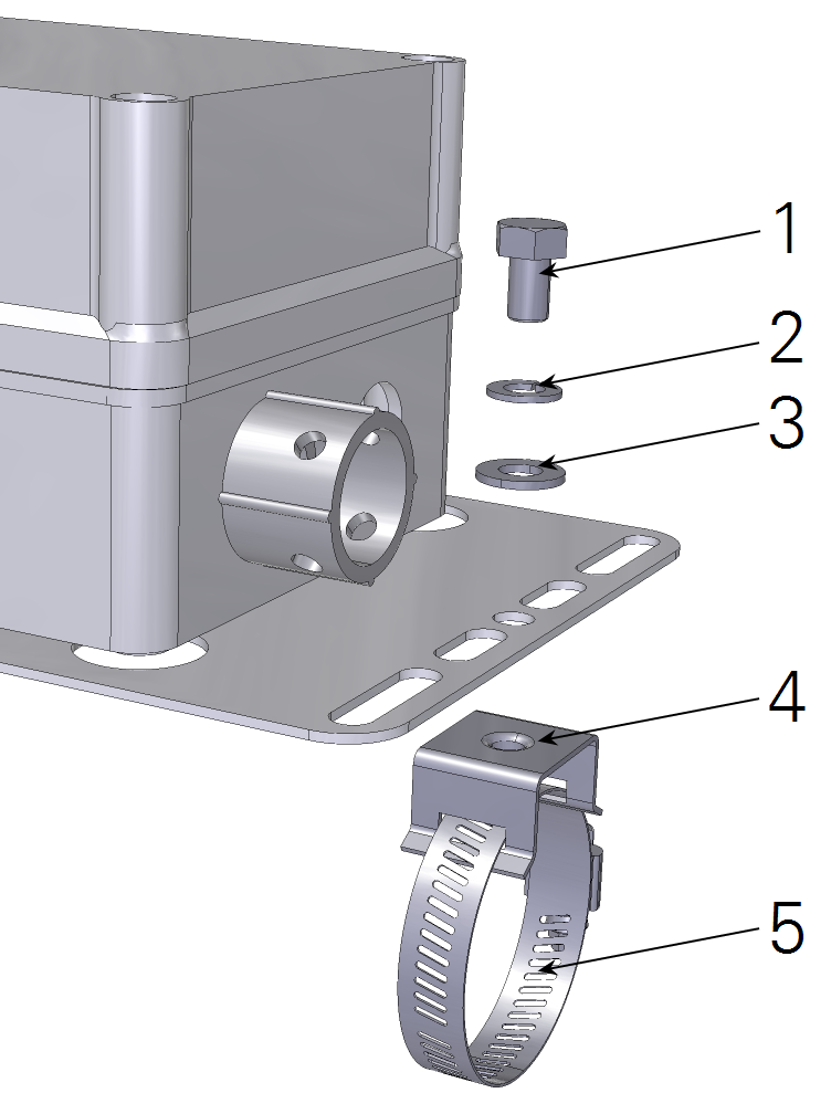 |
1 | 5/16-24 × 1/2” Hex Head Bolt (2; included with bracket) | |
| 2 | 167‑05635 | Lock Washer 5/16” (2) | |
| 3 | 5/16” Flat Washer (2; included with bracket) | ||
| 4 | 235-13234 | Flared-leg Mounting Bracket (2) | |
| 5 | 300-13293 | Band Clamp, 9/16” (2) |
Securing cables
The power supply cable (part number 7900-232 or a user-supplied cable) should be attached securely to the tripod mast or tower leg so that the power distribution box does not bear the weight of the cable.
- Secure the conduit with a cable tie every 1 m (3 feet) so the PDB is not supporting the weight of the conduit and wire.
- Use UV-resistant cable ties.
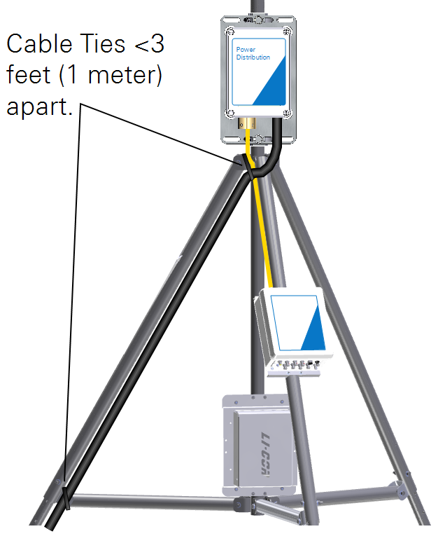
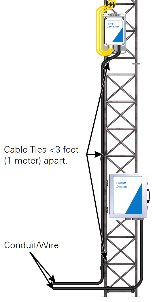
- On the tripod mast or tower, cable ties should be less than three feet (one meter) apart.
- Tighten cable ties snugly around the cable and mast.
- If possible, attach cable ties to a horizontal cross member so that they will not slip with the force of gravity.
- Coil extra cable and attach it to the mast so that it is not resting on the ground.
Instrument power supply cables, which exit the box and connect to the sensors, should be secured to the strain relief fitting as shown in Figure 1‑3. Also secure the cables to the tripod or tower with UV-stabilized cable ties.
Installation
When you install the PDB, it is wise to keep the cables organized and orderly. The effort you put into creating a tidy setup will pay off when you have to troubleshoot a problem with the setup.
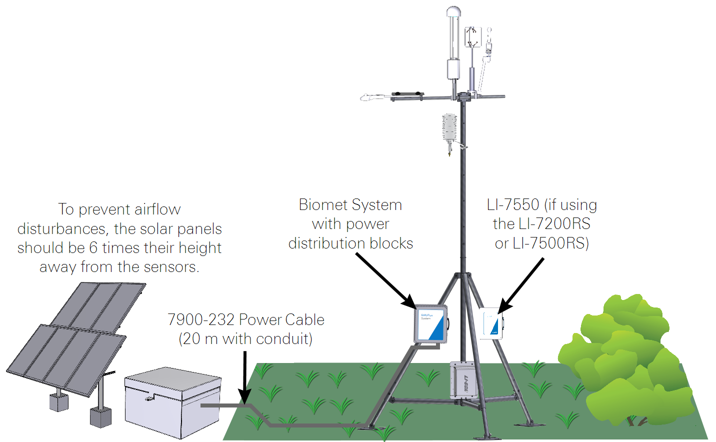
Important: To prevent airflow disturbances that may adversely affect flux results, position the solar power supply downwind (according to the prevailing wind direction) and at a distance of 6x the height of the panels from the anemometer.
Tripod installation
Figure 1‑5 shows power wire routing for a tripod installation.
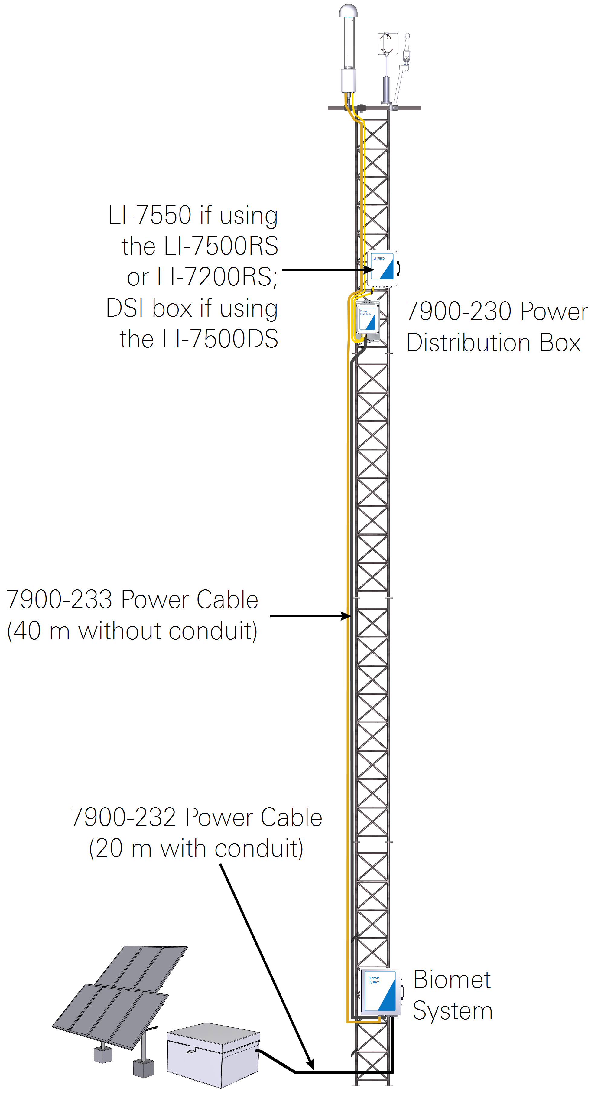
Tower installation
Figure 1‑6 shows configurations for tower installations.