In this section, we describe the batteries, basic hardware connections to gas analyzers, soil temperature probes, and soil collars.
Batteries
The Smart Chamber is designed to use one battery at a time. One fully charged battery provides approximately 17 hours of use with a 2 minute measurement time per collar for 20 collars per hour, or 10 hours use with a 2 minute measurement time per collar for 20 collars per hour when powering the LI-870 CO2/H2O analyzer.
The battery icon at the top-left of the user interface will appear red when the battery runs below 10% of a full charge. To prevent you from starting a measurement and losing data, the Smart Chamber will prevent new measurements from being taken once the battery reaches 3%.
Charging the batteries
Batteries should be fully charged before the first use. First, remove the batteries and battery charger from the packaging, and connect the charger to an AC power source. Insert a battery in the charger dock to begin charging. A full charge is indicated by five black boxes on the charge indicator.
Caution: Charge batteries only with a SMBUS-compliant level 2 or 3 charger. Do not heat above 80 °C. Do not disassemble battery, dispose of in a fire, or short-circuit - may ignite, explode, leak, or get hot, causing personal injury. Replace battery with the same part number only. Use of another battery may present a risk of fire or explosion. Keep away from children.
Installing the battery
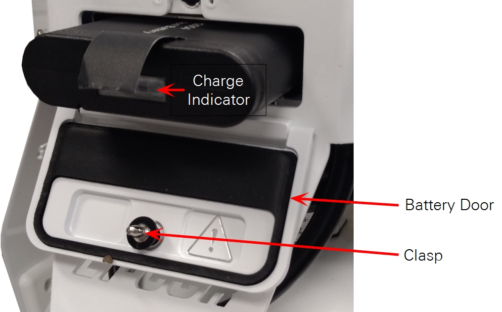
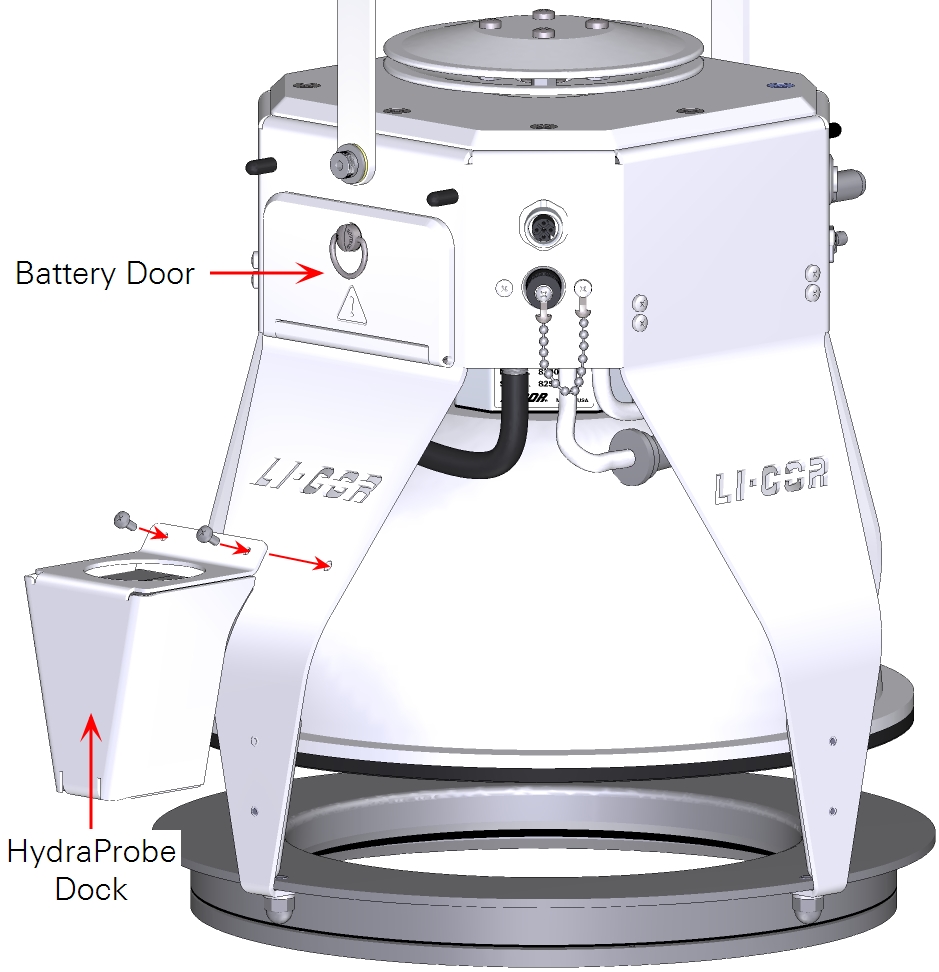
Once the battery is fully charged, open the battery door on the Smart Chamber and insert the battery. The pull-tab on the battery should be on top of the battery. Close the battery door, ensuring that the clasp is seated inside the Smart Chamber. Turn the clasp ¼ of a full turn, and the battery door will close snugly.
Note: Ensure that the battery door is completely closed during normal operation. This will prevent the battery from coming dislodged and causing potential injury or damage to your instrument.
Powering on and off
Press and release the power button to turn on the Smart Chamber. The power button will blink for 10-15 seconds while the instrument boots up. It will appear solid green when the instrument is ready.
To turn off the chamber, press and hold the power button for a few seconds until the button begins blinking green. The button will continue to blink while the instrument goes through a controlled shut-down.
Because the Smart Chamber only uses a single battery, hot-swapping is not possible. Power off the chamber before removing the battery. Be sure you have saved all your settings in the software.
Important: Always power off the Smart Chamber before removing the battery. Removing a battery while the instrument is powered on will cause it to power off immediately. Open data files may be lost and it may cause damage to your instrument or battery.
Connecting gas analyzer tubing and cables
Here we describe three common use cases for the Smart Chamber: Connecting to a LI-COR Trace Gas Analyzer, connecting to an LI-870, and connecting to both a Trace Gas Analyzer and LI-870.
Connecting an LI-7810 or LI-7820 Trace Gas Analyzer
Here we describe how to connect the Smart Chamber to LI-7810 or LI-7820 Trace Gas Analyzer. This section assumes you are familiar with the basic operation of the Trace Gas Analyzer.
Caution: LI-COR Trace Gas Analyzers are water resistant but are not waterproof. They should not be allowed to sit in standing water, be exposed to driving rain, or be deployed outdoors without weather protection. If there is any chance that water will be drawn into the inlet, use a water trap to collect the water before it is drawn into the analyzer. If water is drawn into the analyzer it will require factory repair.
LI-COR Trace Gas Analyzers provide data to the Smart Chamber that is used to compute fully-processed fluxes in the field for gases beyond CO2, like CH4 with the LI-7810 CH4/CO2/H2O Analyzer.
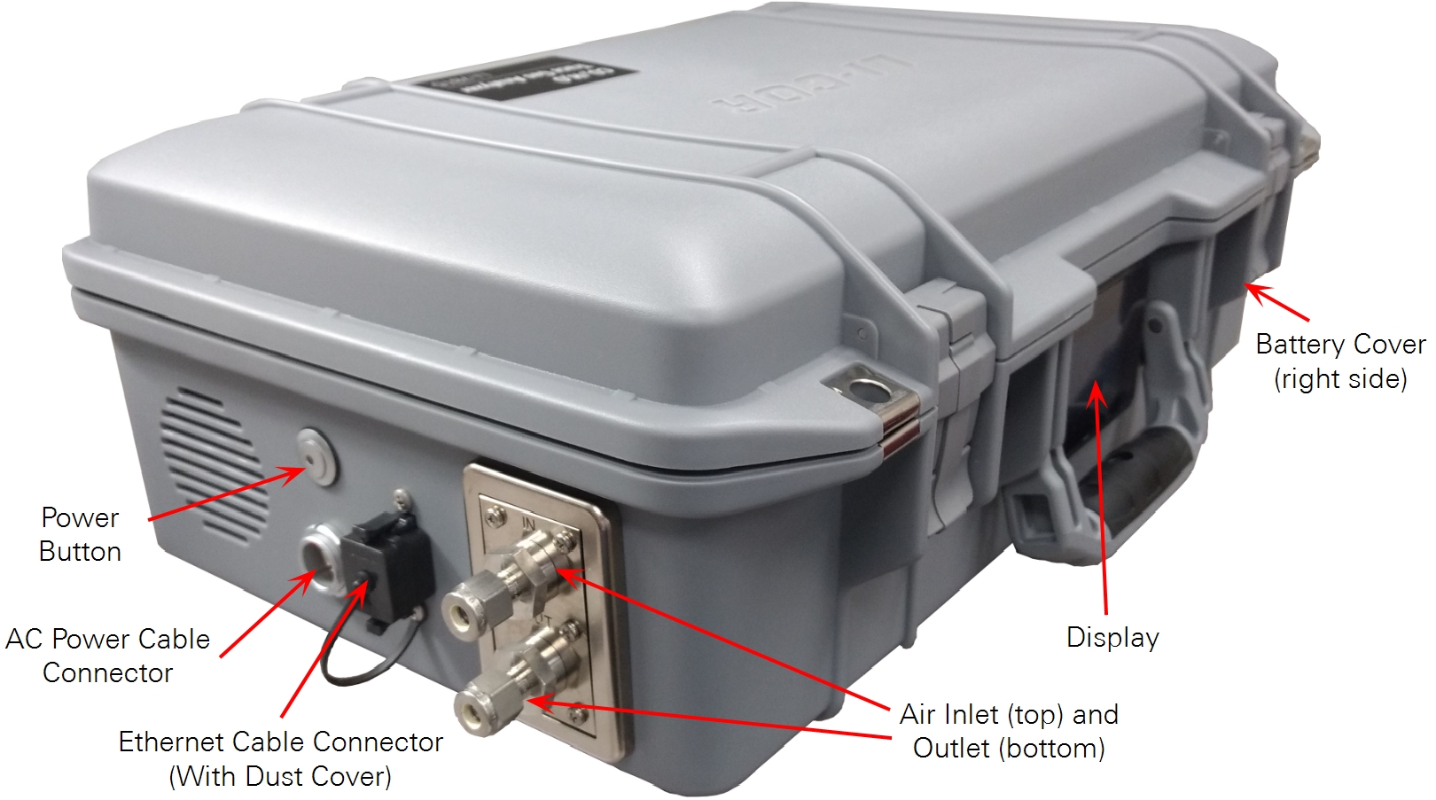
The Smart Chamber connects with LI-COR Trace Gas Analyzers with a RJ-45 Ethernet cable, which is part of the Trace Gas Analyzer Cable Assembly (part number 9982-009). The cable assembly must be ordered separately.
Note: Only use the supplied Cat. 5e RJ45 Ethernet cable from the LI-78xx Trace Gas Analyzer to Smart Chamber Cable Assembly (part number 9982-009 (1.2 m) or 9982-011 (2 m)).
The air inlet draws a gas sample into the gas analyzer through a ¼" compression fitting connector (part number 300-15025), which is included with your Trace Gas Analyzer. Bev-a-Line® tubing (¼" outside diameter) is included in the cable assembly, and an additional nuts and ferrule set (part number 300-15024) is included in the Trace Gas Analyzer Accessory Kit (part number 9978-195). Do not restrict or apply a vacuum to the air outlet.
Connecting the components
Connecting the Smart Chamber to a LI-COR Trace Gas Analyzer only requires a few steps.
1. Install batteries in the Trace Gas Analyzer and power it on.
Allow 25 to 30 minutes for it to warm up before making measurements. You can see the instrument status on the display panel.
2. Connect the tubing and cable assembly to the Trace Gas Analyzer
For soil gas flux measurements, use a length of cable that allows you to comfortably maneuver the Smart Chamber. Too short a length may cause tugging problems and leaks, while a connection that is too long is prone to snags and damage. The 1.2-meter cable assembly (part number 9982-009) is recommended for hand-carrying, while the 2-meter assembly (part number 9982-011) is recommenced for use with the backpack kit accessory (see Using the backpack accessory).
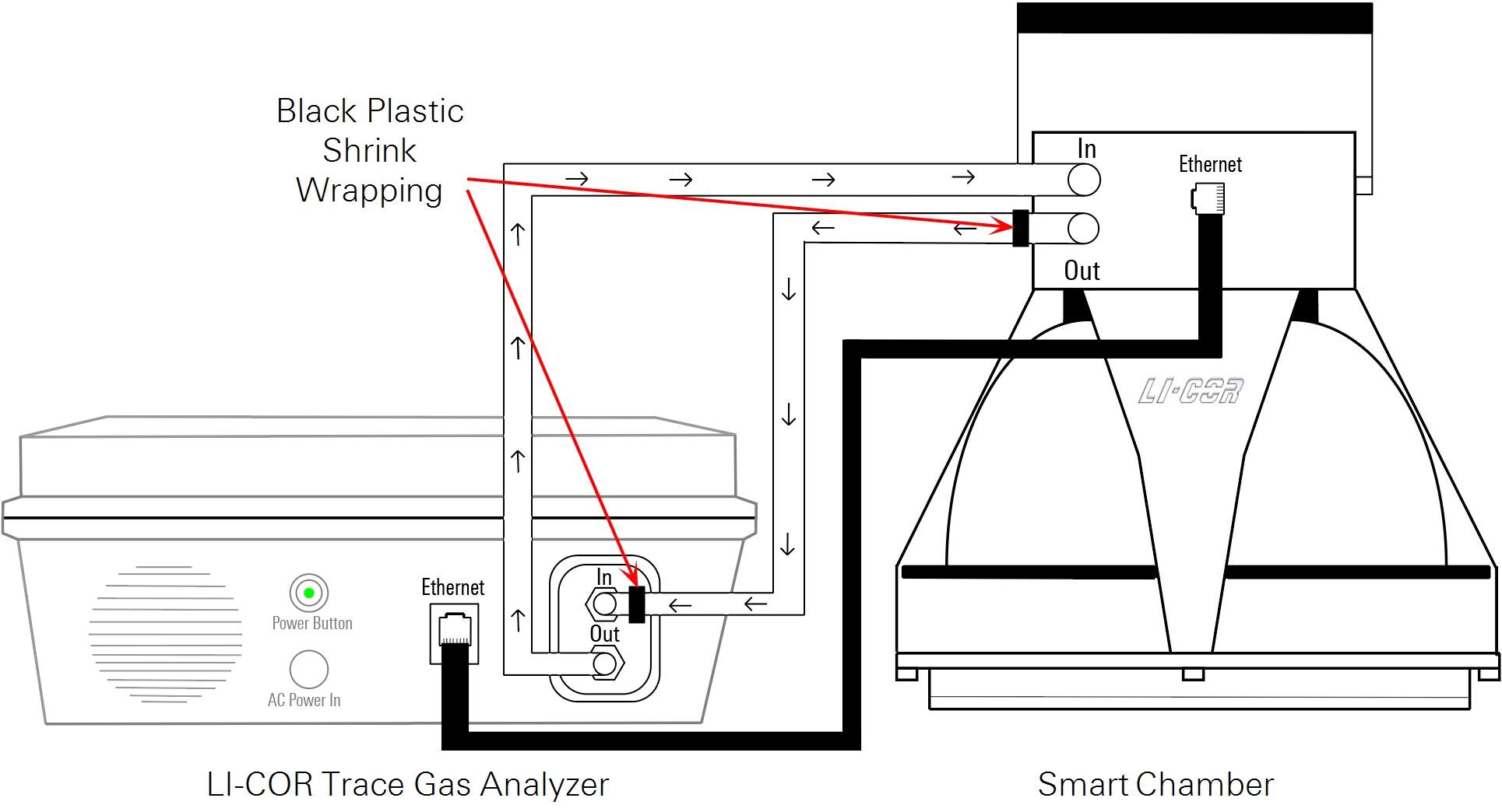
Important: The tubing that connects the Smart Chamber air outlet to the Trace Gas Analyzer air inlet is labeled on each end with black plastic shrink wrap. Ensure this tube is attached to the air-in port on the Trace Gas Analyzer. Connecting the tubing improperly may damage your instruments or cause them to not work properly.
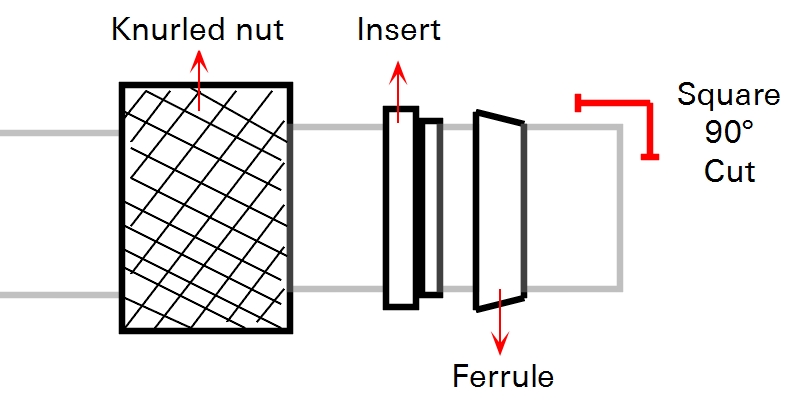
The tubing in the cable assembly comes pre-assembled with a knurled nut (part number 300-05896), stainless steel inserts (part number 300-18126), and stainless steel ferrules (part number 300-15024) for connecting to the analyzer.
Thread the nuts on to the compression fittings on your analyzer and connect the quick-connect fittings to your Smart Chamber. To ensure that the fitting forms a seal, tighten the nut over the ferrule set until it is snug, and then tighten it an additional ¼ turn.
3. Attach the cable assembly to the Smart Chamber
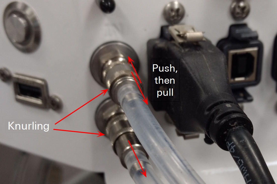
Insert the Ethernet cable and simply press the steel quick-connect fittings in towards the chamber head to attach the tubing. To disconnect the tubing, slide the knurled piece of the Smart Chamber air inlet connector inward and pull the tube out. For the outlet tubing, pull the knurled piece of the Smart Chamber connector outwards from the chamber head and pull on the tubing to release.
Note: A USB-B to USB-A connector is included in the event that you are not using Wi-Fi and need to connect your Smart Chamber to a computer while the Ethernet port is being used by the Smart Chamber to LI-COR Trace Gas Analyzer cable assembly.
Using the backpack accessory
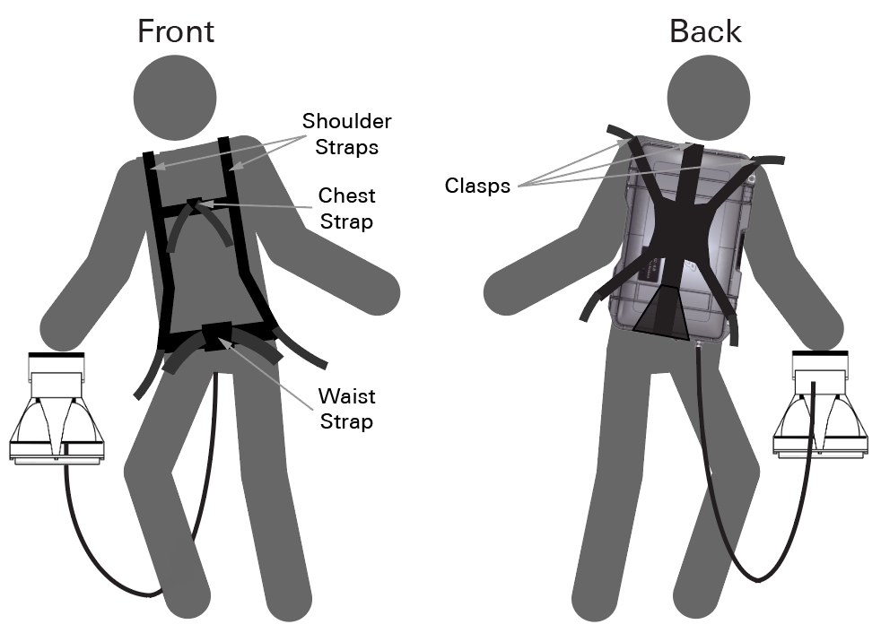
The backpack kit (part number 610-17341) is used to carry a Trace Gas Analyzer on your back. To use the backpack kit, secure the analyzer with straps. The connector panel should be facing toward the bottom. Close the clasps and tighten the straps tightly around the instrument. Do not set the instrument down in such a manner that the vents become blocked or immersed in standing water. Tighten the shoulder straps snugly, then clip and tighten the chest and waist straps.
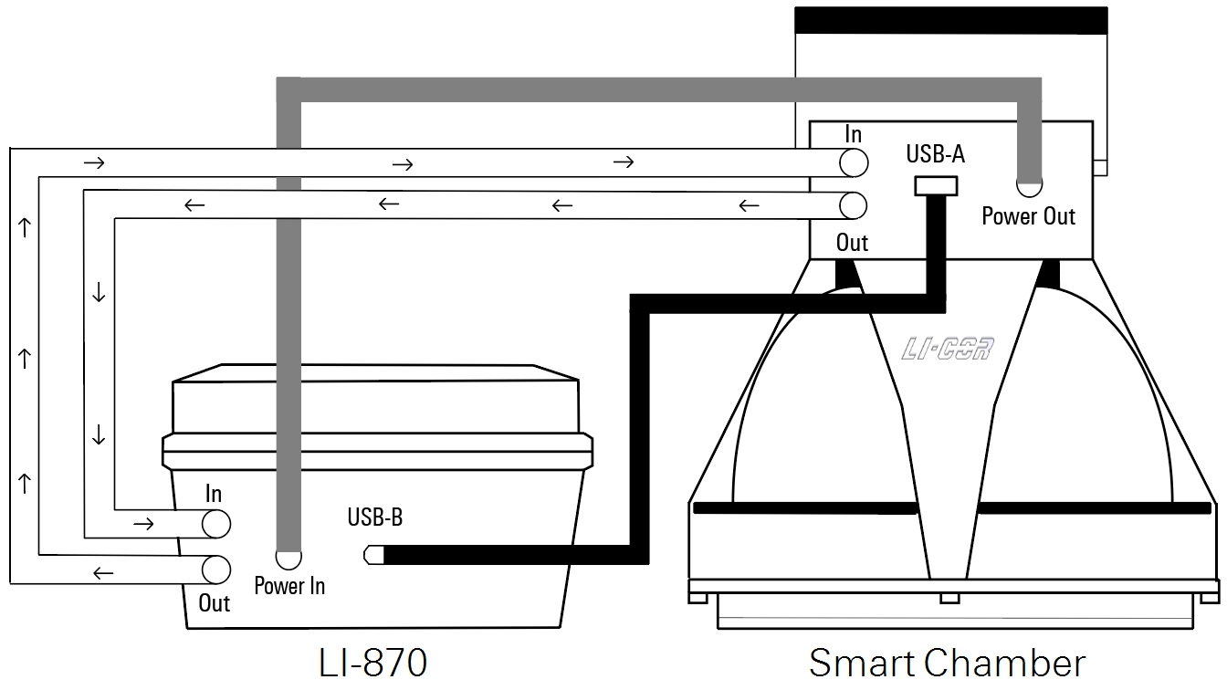
Connecting an LI-870
The LI-870 offers portable, precise measurements of CO2 concentration for flux measurements with the Smart Chamber. Power is supplied to the LI-870 directly from the Smart Chamber.
A complete user manual is included with the LI-870. The material can also be found at the LI-COR support site at licor.com/support. This section describes how to connect the LI-870 to the Smart Chamber.
The Smart Chamber and LI-870 each use metal quick-connects for air tubing, and a male and female connector come factory-installed on each end of the LI-870 cable assembly, so no additional preparations are necessary unless you are replacing the quick-connects.
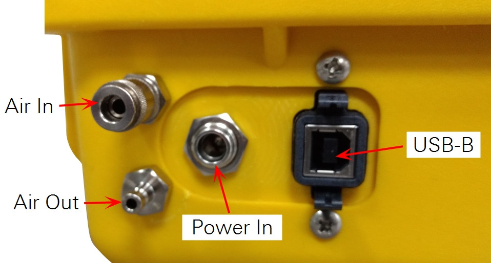
Attach the air tubing quick-connects, male USB-B connector, and power cable connector to the LI-870.
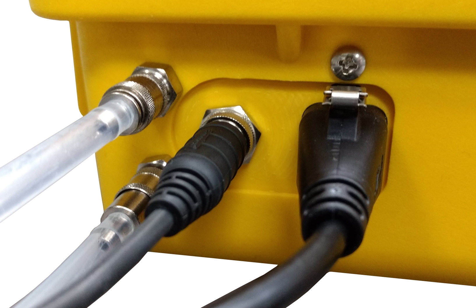
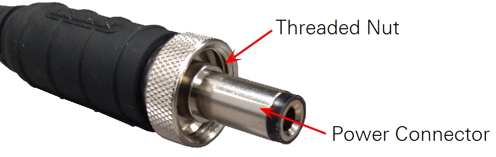
For both ends of the power connector, note that the cable ending consists of the power connector itself and an outer nut that must be screwed onto a nut on the LI-870 or Smart Chamber.
Complete the connection by attaching the air tubing quick-connects, male USB-A connector, and power cable connector to the Smart Chamber.
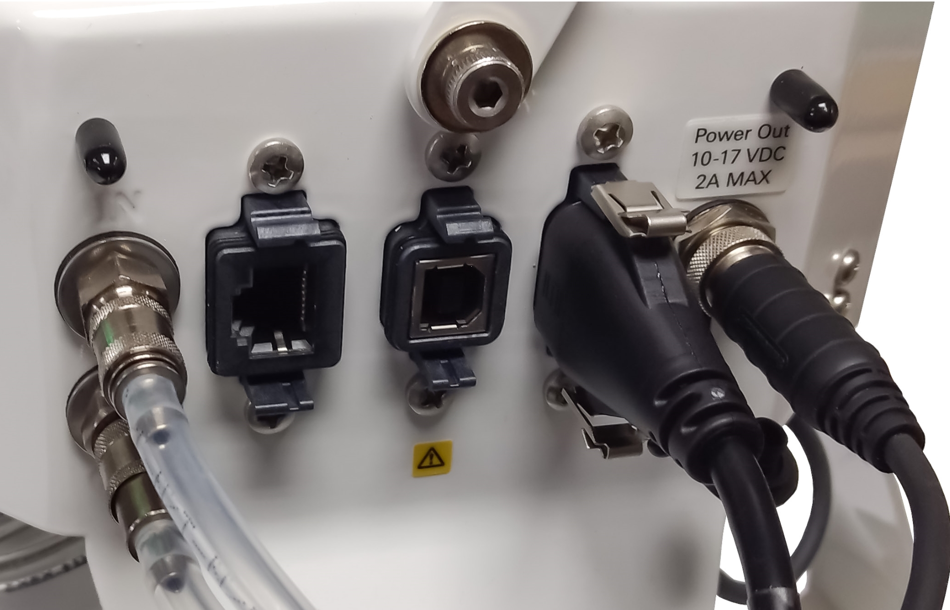
Note: Only use the supplied USB-A to USB-B cable from the LI-870 to Smart Chamber cable assembly (part number 9982-010).
Warning: Only use the power cable supplied with the LI-870 cable assembly (part number 9982-010), and do not attempt to power any other devices with the Smart Chamber. Drawing a current in excess of 2 amps will trip the self-resetting breaker. If you trip the self-resetting breaker, you will need to wait for a few minutes before attempting to re-power the LI-870.
Powering on the Smart Chamber will also power up the LI-870 (assuming you are properly connected). The optical bench of the LI-870 must be allowed to warm up before making measurements, which may take up to 10 or 15 minutes, depending on ambient temperature.
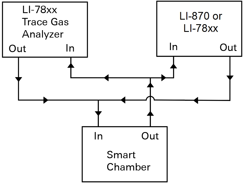
Using the LI-870 and a LI-COR Trace Gas Analyzer or multiple TGAs concurrently
The Smart Chamber can be simultaneously configured with the LI-COR Trace Gas Analyzer and LI-870 or two TGAs. The Smart Chamber can simultaneously connect multiple gas analyzers using the T-split tubing (part number: 9982-073) to complete the connection. Shown below is a configuration using two gas analyzers.
Connect the long leg (15 cm) to the respective IN or OUT port on the Smart Chamber. Then connect the short legs (8 cm) to the respective ends of the analyzer air in and air out tubing.
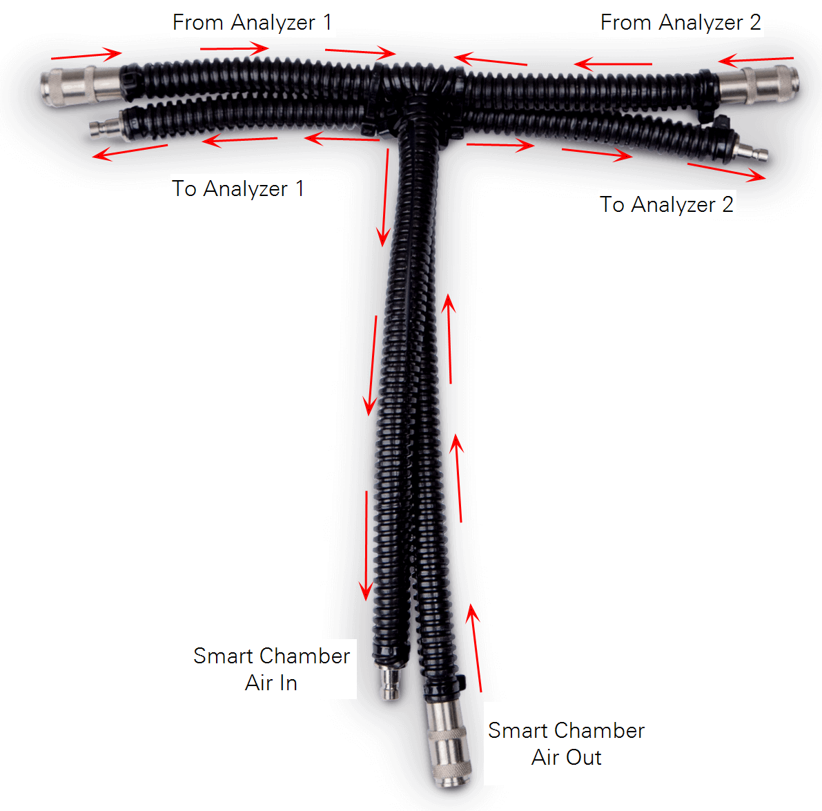
The T-split tubing will add 30 cm to the analyzer tubing that must be evenly split between the tubing lengths of both analyzers (add 15 cm to each).
Be sure the volume is represented correctly in the software. 100 cm (1 meter) of ¼" outer-diameter Bev-A-Line® tubing adds 7.9 cm3, or approximately 0.079 cm3 of added volume per cm of tubing.
You'll enter this volume in the Smart Chamber software when configuring your measurements. See Measurement tutorial.
Connecting soil probes
Soil moisture and temperature are not essential for the flux calculation but can provide useful ancillary data. The Smart Chamber supports several options for soil temperature measurements: the Stevens HydraProbe (part number 900-19016), the LI-COR Soil Temperature Thermocouple (part number 9982-080), or the discontinued Omega Soil Temperature Thermocouple (part number 6000-09TC).
The HydraProbe measures soil moisture content, salinity, and temperature, but the location and the slow response time of the temperature reported by the HydraProbe is not ideal for survey measurements. Therefore, we recommend using the Soil Temperature Thermocouple or Omega thermocouple for soil temperature measurements.
Note: When using both the Stevens HydraProbe and a soil temperature thermocouple, the radio frequency generated by the HydraProbe may interfere slightly with the thermocouple temperature reading. For best results, we recommend placing the probes at least 30 cm apart.
Stevens HydraProbe
A dock for the HydraProbe must be installed on the smart chamber.
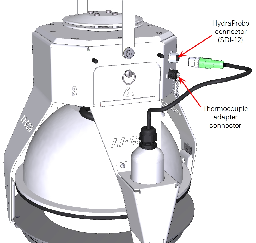
The HydraProbe uses the SDI-12 communication protocol. The cable connector has a marking that faces up and a key that must be aligned before the connector can be tightened. To connect the HydraProbe, align the key and twist the textured metal piece ¼ turn clockwise. To disconnect the probe, turn the same piece ¼ turn counter-clockwise and pull the connector out away from the chamber head.
HydraProbes with serial numbers 268000 and higher feature a generic calibration that is suitable for a range of soil types. Earlier models require you to enter the soil type in order to compute accurate measurements. The Smart Chamber records measurements from the HydraProbe while a measurement is underway. It stops recording as soon as the repetition is complete.
Soil temperature thermocouple adapter
A Type-E soil temperature thermocouple adapter is included in the Smart Chamber spares kit (part number 9968-162), which allows for configuration with any Type-E thermocouple, or a soil temperature thermocouple (discontinued Omega Probe; part number 6000-09TC or current LI-COR probe; part number 9982-080).

Warning: The tip of the Omega Soil Temperature Thermocouple is EXTREMELY sharp. Handle with caution, keep the protective rubber tip in place when not in use, and use the provided foam sheath when transporting the probe. Do not force the probe into hard soils, or it may break.
Connect the male end of the Omega thermocouple connector into the female end of the thermocouple adapter, taking care to align the positive and negative signs on each end. Follow the same alignment precautions if using a different Type-E thermocouple. Remove the cap covering the thermocouple connector on the Smart Chamber and insert the thermocouple adapter plug.
Installing soil collars
Although the ideal measurement system would not alter the soil in any way, soil collars present an acceptable and necessary tradeoff between affecting the soil environment and measuring actual soil gas flux. Soil collars have several advantages over direct insertion of the chamber into the soil. First, because soil collars are installed several hours or days ahead of measurements, the insertion does not affect measurements. Second, collars make it possible to make repeated measurements at the exact same location over time.
Note: For the best results, install your soil collars at least 6 hours prior to measurements. The earlier you install collars, the better. Installing 24 hours or more prior to measurements is ideal.
Tips for soil collars
- Pay attention to the soil type. If you are using the HydraProbe, you should enter the soil type to improve measurements from the HydraProbe.
- You can test to see if the flux has stabilized by making a measurement immediately after installing the soil collar, and then by making subsequent measurements at regular intervals after installation. Note, however, that soil surface gas flux depends on the time of day, and variation over the diurnal cycle can be quite large.
- In hard or compacted soils, you may need to create a channel around the collar with a knife or trowel before insertion.
- In soft soils, you can lay a piece of wood across the collar, and hit the wood with a hammer or mallet to drive the collar into the soil.
- Although some collars are included with your Smart Chamber, you can also create your own collars. See Making your own soil collars for instructions.
Insertion depth
The optimal collar height will depend upon site conditions and the length of time the collars will be used at a given site. At a minimum, the collar should be inserted into the soil to a depth that gives a solid foundation so the collar does not move when placing the chamber on the collar. As insertion depth is increased, lateral diffusion of trace gases in the soil column below the chamber will be reduced. The advantage of this is that lateral diffusion can be a source of error in the measurement, but the disadvantage is that as insertion depth increases, the possibility of root shearing increases. Collars may become loose over time and should be moved if this occurs.
Collars should extend a minimum of 2 cm above the soil surface. Collars can extend above the soil more than 3 cm, but with greater extension there is increased shading and perturbation of air movement. Over the long term, these perturbations could result in changes of evaporation rate, soil temperature, and soil moisture.
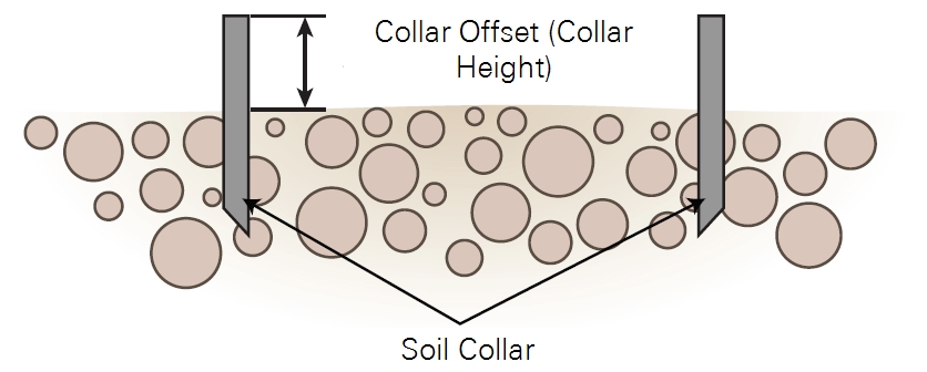
Measuring the collar offset
The collar offset is used to the determine the volume of air inside the soil collar, which is in turn used to calculate the total system volume. Total system volume is an important parameter of the flux calculation, so it should be determined as accurately as possible. The collar offset is measured by the distance between the soil surface and the top of the soil collar.
For the most accurate measurements, it is recommended that you measure collar height in 3-4 places and average these numbers. This is especially important when collars are installed in uneven or sloping soil.
Make sure the soil collar is not disturbed when placing the chamber on it. The chamber edge should be as close to the soil surface as practical (within 1-2 cm) so that air flow within the chamber causes mixing near the soil surface.
Making your own soil collars
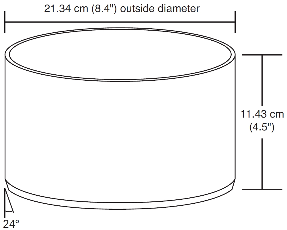
You can make your own collars if you can acquire suitable pipe. Large soil collars from LI-COR are constructed from thick-walled, 8-inch SDR 35 PVC pipe. This material is widely available in the United States. In other countries, you may need to special order the PVC pipe or find a similar alternative.
To construct a collar, cut a length of pipe to approximately 11.43 cm. Then, use a grinder or coarse file to bevel the bottom edge to a 24° angle. The bevel is optional but does allow for easier insertion of the collar into the soil.
- Inside Diameter: 20.1 cm ± 0.03 cm
- Outside Diameter: 21.34 cm
- Height: 11.43 cm