Replacing the Source and Detector in the LI-8x0 Analyzers and LI-8100/A
Printable PDF: Replacing the Source and Detector in the LI-8x0 Analyzers and LI-8100/A
(8x0-and-8100-Source-and-Detector-InstallGuide_17308)
Download this content as a pdf.
This document describes how to replace the optical source and detector on the LI-830, LI-850, and LI-870 gas analyzers, legacy LI-800, LI-820, LI-840, and LI-840A gas analyzers, and the LI-8100/A Automated Soil CO2 Flux System.
| Part Numbers | ||||
|---|---|---|---|---|
| Source | Detector | 14 cm Bench | 5 cm Bench | |
| LI-850 / LI-870 | 800-902 | 800-918 | 800-904 | n/a |
| LI-830 | 800-902 | 800-916 | 800-904 | n/a |
| LI-840/A | 800-902 | 800-906 | 800-904 | n/a |
| LI-820 | 800-902 | 800-903 | 800-904 | 800-905 |
| LI-800 | 800-902 | 800-903 | 800-904 | 800-905 |
| LI-8100A | 8100-902 | 800-906 | 800-904 | n/a |
Instructions for the LI-800, LI-820, LI-830, LI-840/A, LI-850, and LI-870 are below. For details on the LI-8100/A, see LI-8100/A Source and Detector Replacement.
LI-800, LI-820, LI-830, LI-840/A, LI-850, and LI-870
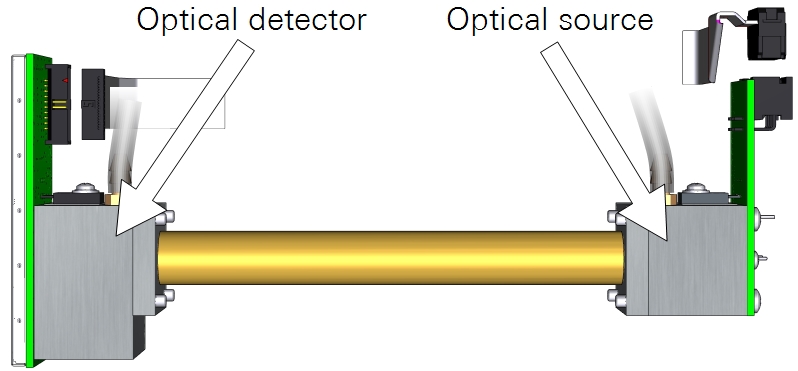
The optical source and detector may need to be replaced if one fails. The life expectancy of the source is typically >20,000 hours, or >2 years of continuous operation, but this will vary depending upon the number or warm-up cycles, vibration, and other factors. Typically, detectors need to be replaced rarely, if ever.
Disassembly
You'll need #1 or #2 Phillips screwdriver and a clippers or utility knife. The installation, including calibration, may take an experienced technician 30 minutes to 1 hour. If the instrument has been running recently, the bench may be hot to the touch. Let it cool for 5 or 10 minutes after powering off if needed.
Note: Be sure that you are properly grounded to avoid electrostatic discharge that can damage the electronics. Use an anti-static wrist strap, electrostatic discharge grounding mat, or occasionally touch bare metal that has a clear path to ground, such as an unpainted computer case.
- Power off the gas analyzer and remove the top cover (LI-800, LI-820, LI-830, LI-840/A and LI-850) or open the case (LI-870 only).
- The LI-800, LI-820, LI-830, LI-840/A and LI-850 top cover is held in place by 6 screws. Loosen the screws and lift off the cover. If there is a ribbon cable connecting the top panel, be careful not to strain it. The LI-870 is opened by removing two screws that hold the case closed; then remove four screws that secure the optical bench cover.
- Unplug the source and detector ribbon cables from the source and detector.
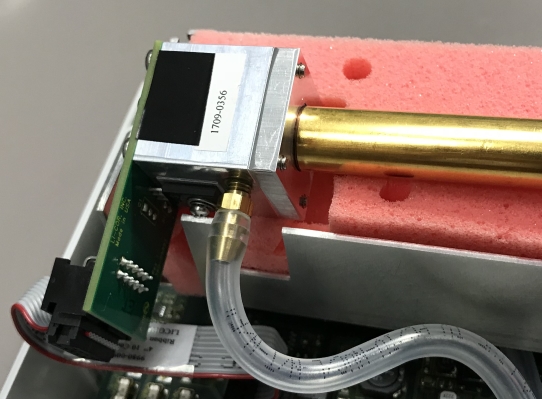
- Lift the optical bench out of the foam insulation.
Replacing the Optical Source
With the optical bench free of the case (except the tubing), you can remove the source from the optical bench.
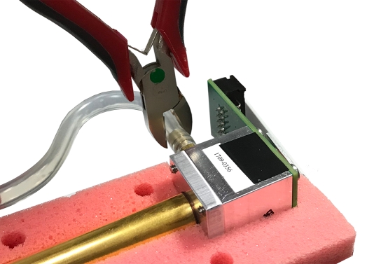
- Remove the tube from the source.
- The simplest way is to cut the tubing as close to the hose barb as possible.
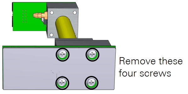
- Remove the four larger screws from the optical source.
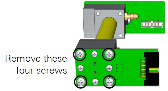
- Separate the source from the optical path.
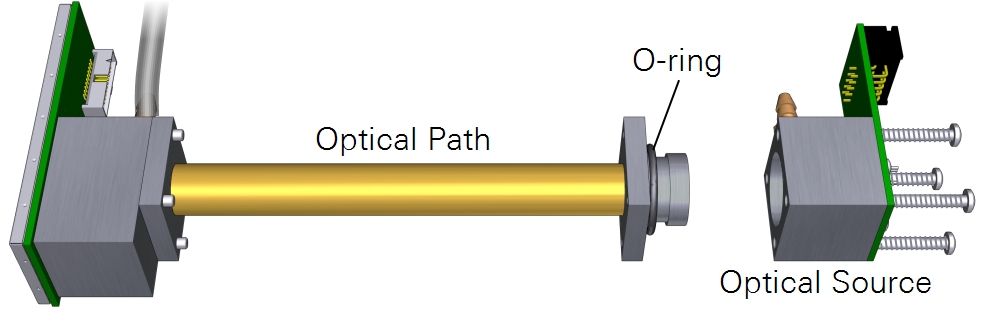
- Be sure that the inside of the optical path is clean—free of dust and other contaminants. Clean it if needed, as described in the instruction manual.
- Install the new O-ring that is included with the source.
- Install the replacement optical source.
- Tighten the screws firmly.
- Press the air-in tube over the hosebarb—be sure it covers both barbs on the hosebarb.
- Removing a section of tubing will reduce the total volume of the analyzer, and this may affect some characteristics of the analyzer, such as the T90 specification, but the reduction in volume is generally negligible. There is enough slack in the original tubing for a single replacement of the source, but if you replace it more than once, you may need to replace the entire segment of tubing. Should you choose to recalculate system volume after removing a segment of tubing (which is not required), the Bev-A-Line® has an inside diameter of 1/8" (0.3175 cm). If you removed 1 cm (0.39 inches) of tube, the volume removed is about 0.079 cm3 (π × r2 × length; 3.14 × (0.3175 cm / 2)2 × 1 cm = 0.079 cm3).
- Work the optical bench into the foam.
- Be sure that the bench is secured tightly in the foam insulation and that no parts are in direct contact with the surrounding metal cradle.
- Connect the ribbon cables that were removed previously.
- Reassemble the instrument.
- Make sure that the foam insulation on the inside top cover is positioned over the optical bench; it is required for thermal stability. Reconnect the top cover ribbon cable and then install the top cover.
- In the LI-830, LI-850, and LI-870, reset the source hours to "0".
- The LI-830, LI-850, and LI-870 record the number or operating hours for the optical source. You should reset this count after replacing the source. Connect using the software and then click Settings > Diagnostics and click the gear button near Source, and then reset the hours.
- Zero and span the analyzer as described in the instruction manual.
- A simple zero and span will be adequate if the span gas is close to the concentrations you will measure. A dual span, however, will bring the instrument performance within specifications across the full measurement range. If you do not have zero and span gases, send the instrument back to LI-COR for a factory recalibration.
Replacing the Optical Detector
You can also replace the optical detector.
- Remove the tube from the detector.
- When replacing the detector on the LI-830, LI-850, or LI-870, you will probably need to replace the entire segment of urethane tubing, because cutting a portion to remove it from the hose barb will not leave enough tubing to re-connect using the original segment. A replacement segment of urethane tubing is included in the detector replacement kit for this purpose. On the LI-800, LI-820, or LI-840/A, the tubing is long enough to reconnect.
-
- Remove the four screws that secure the optical detector and shield.
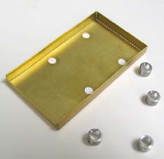
- On the LI-840/A, there are four spacers between the shield and detector. Collect the four spacers.
- Separate the detector from the optical path.
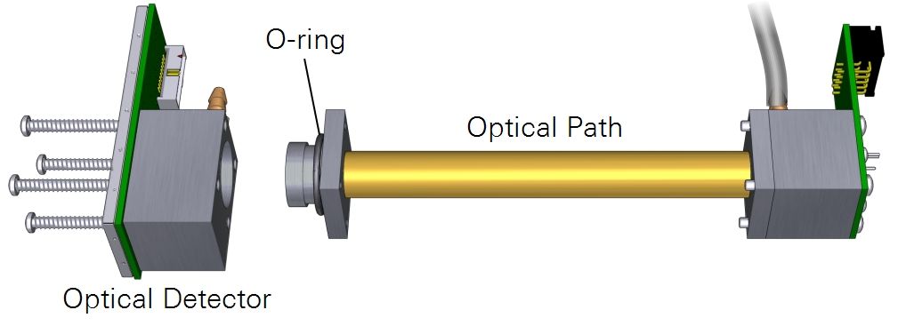
- Be sure that the inside of the optical path is clean. It should be free of dust and other contaminants. Clean it if needed, as described in the instruction manual.
- Install the new O-ring that is included with the detector.
- Install the replacement optical detector.
- On the LI-840/A, place the four spacers on the screws so they fit between the shield and detector circuit board. Tighten the screws firmly.
- Press the tube over the hosebarb—be sure it covers both barbs on the hosebarb.
- Work the optical bench into the foam.
- Connect the wiring harnesses to the detector and source.
- Reassemble the instrument.
- Make sure that the foam insulation on the inside top cover is positioned over the optical bench; it is required for thermal stability. Reconnect the top cover ribbon cable and then install the top cover.
- Important: LI-840's that are running older software must be updated to the latest LI-840A embedded software, which is available for free from licor.com/support/LI-840A/software.html.
- Zero and span the analyzer as described in the instruction manual.
- A simple zero and span will be adequate if the span gas is close to the concentrations you will measure. A dual span, however, will bring the instrument performance within specifications across the full measurement range. If you do not have zero and span gases, send the instrument back to LI-COR for a factory recalibration.