Legs and Base
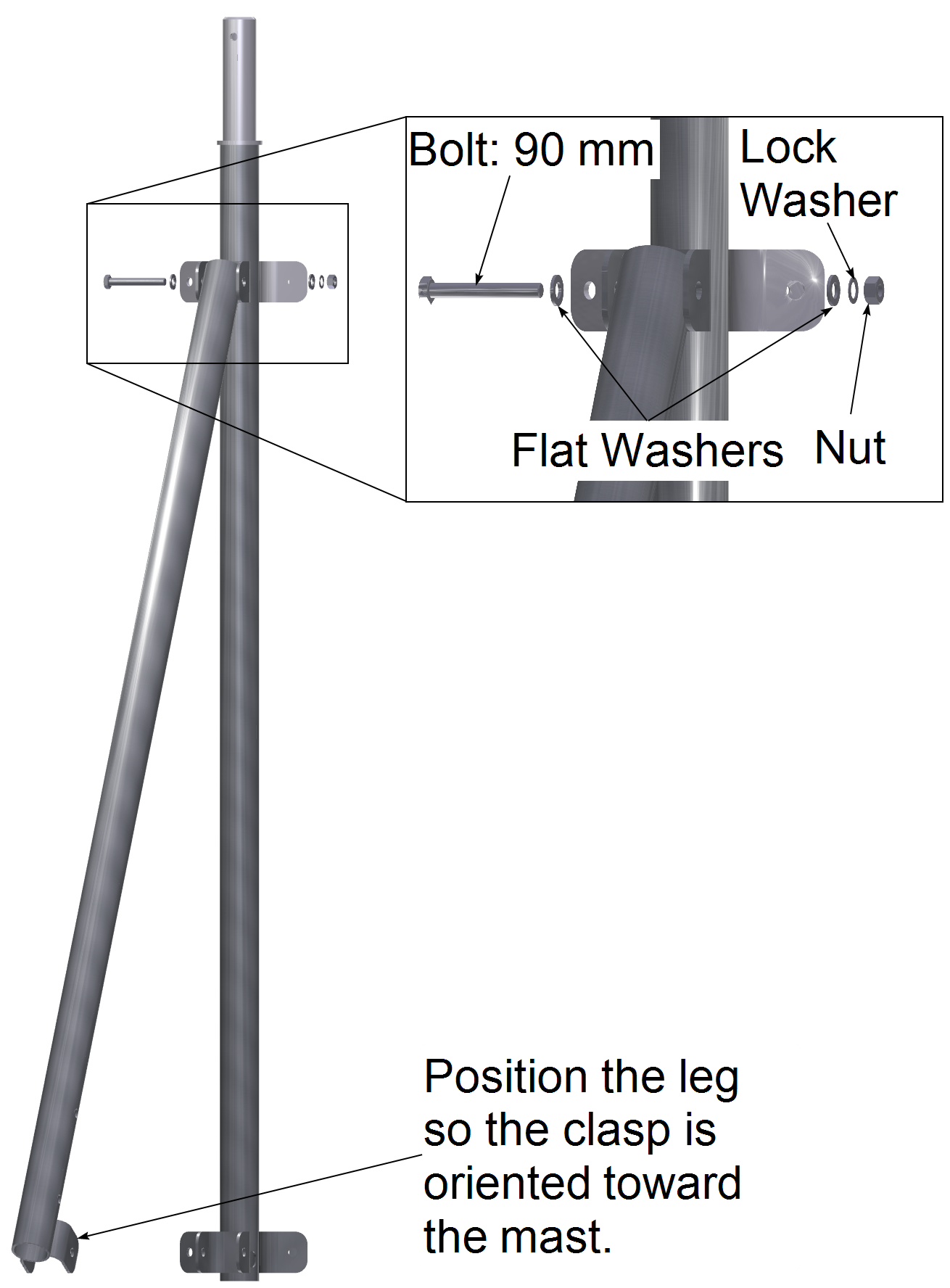
1. Attach One Leg to the Mast
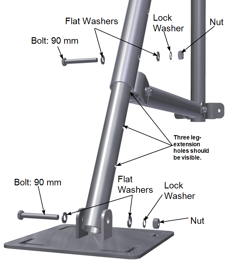
Gather the following components for one leg: lower mast, leg, leg extension, leg brace, foot, 90 mm bolts, lock washers, flat washers, and nuts.
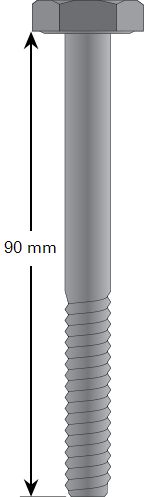
Attach the leg to the mast as shown below. Tighten the nut(s) to finger-tight for now. When the tripod mast and legs are completely assembled, tighten it to 23 N•m (204 lb•in; 17 lb•ft) using a torque wrench.
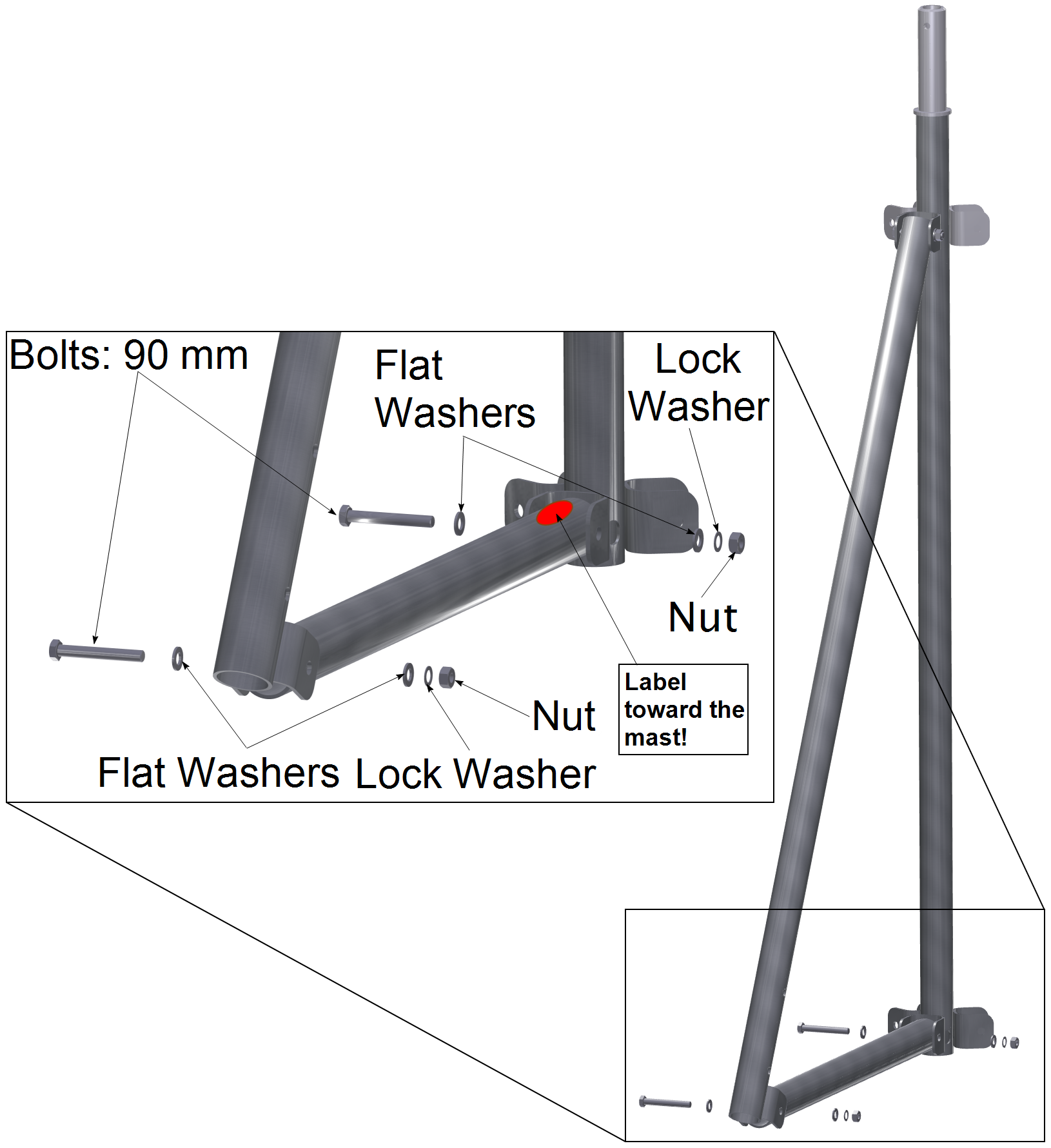
2. Attach the Leg Brace to the Mast and Leg
Attach the leg brace between the leg and mast as shown below. Be sure the warning label is near the mast.
 Warning: Pinch point. Use caution during assembly.
Tighten the nut(s) to finger-tight for now. When the tripod mast and legs are completely assembled, tighten it to 23 N•m (204 lb•in; 17 lb•ft) using a torque wrench.
3. Attach the Leg Extension and Foot
Attach the leg extension and foot to the leg, as shown below.
Warning: Pinch point. Use caution during assembly.
Tighten the nut(s) to finger-tight for now. When the tripod mast and legs are completely assembled, tighten it to 23 N•m (204 lb•in; 17 lb•ft) using a torque wrench.
4. Attach the Remaining Two Legs
Repeat the steps above with the remaining two legs.
Mast and Guy Wires
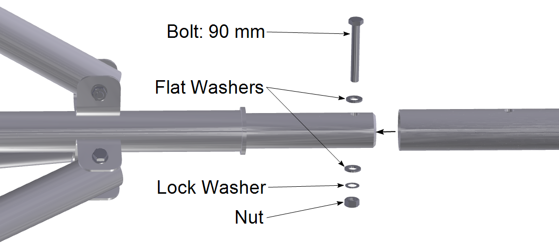
5. Install the Upper Mast
The upper mast extends the reach of the tripod up to 4 meters (13.12 feet). Slide the upper mast over the lower mast. Secure it with a 90 mm bolt, nut, and two washers. Tighten the nut to 23 N•m (204 lb•in; 17 lb•ft) using a torque wrench.
 Warning: Pinch point. Use caution during assembly.
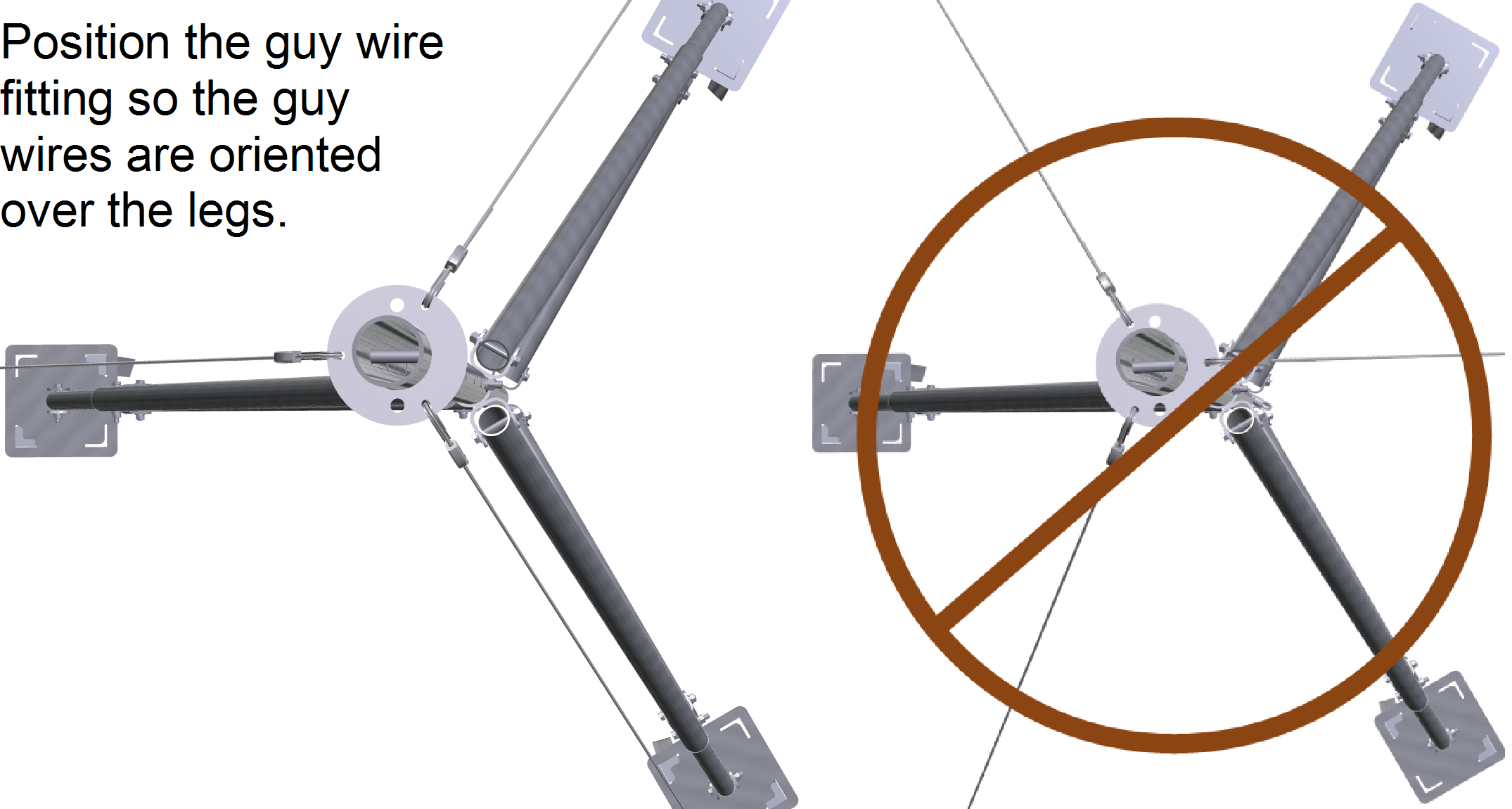
6. Install the Guy Wire Fitting
Think ahead about the desired position of the tripod and sensors with respect to the measurement height and sensor orientation. Install the guy wire fitting at the proper height to ensure that the guy wires will extend to the ground at a 45° angle (see Install the Guy Anchors and Wires).
Caution: The guy wire fitting should be placed on the mast extension prior to adding the cross arm. The collar provides an additional safety stop in the event that the cross arm bracket slips on the mast.
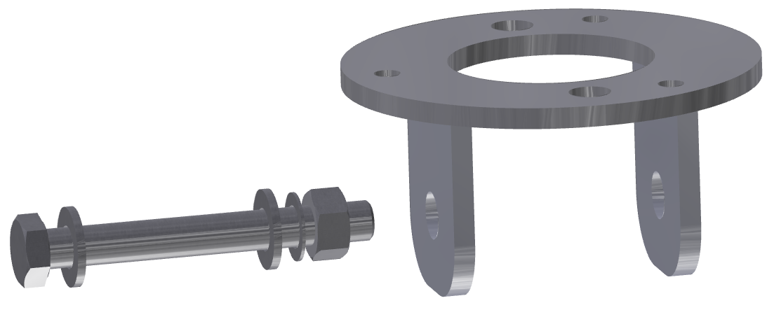
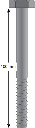
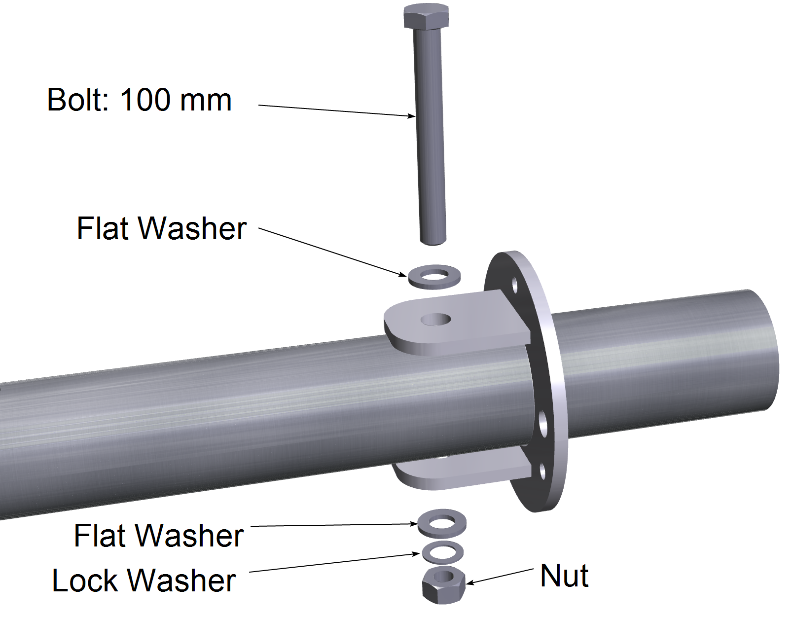
Position the guy wire fitting on the mast so that is as close as possible to the anticipated cross arm location. It must still be under the cross arm. Secure it with a 100 mm bolt, nut, two flat washers, and a lock washer. Tighten the nut 23 N•m (204 lbs•in; 17 lb•ft).
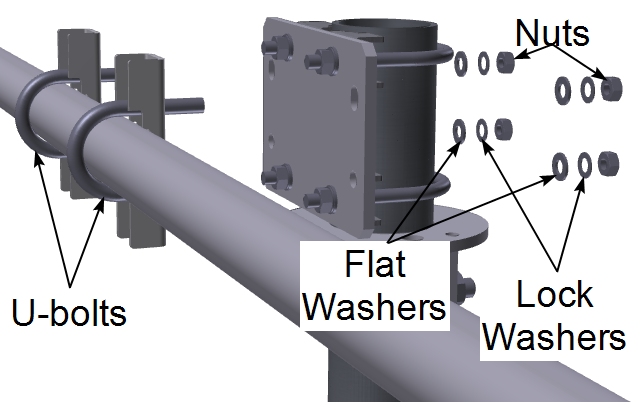
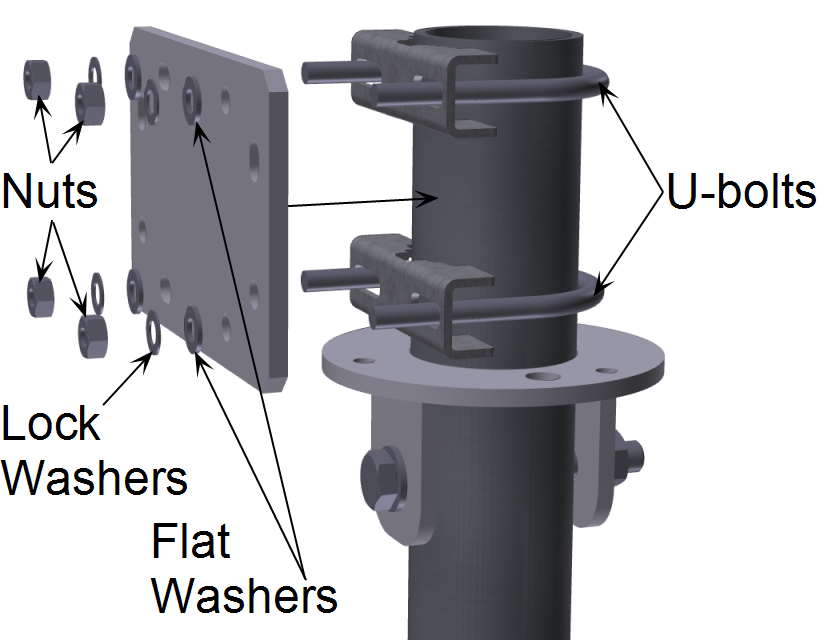
The cross arm mounts to the mast with the cross arm bracket. Attach the bracket to the mast with U-bolts, flat washers (24 mm M8), lock washers (M8) and nuts (13 mm M8) from the cross-arm bracket hardware bag.
Warning: Pinch point. Use caution during assembly.
Observe the proper orientation of the cross arm bracket, as shown in the image below.
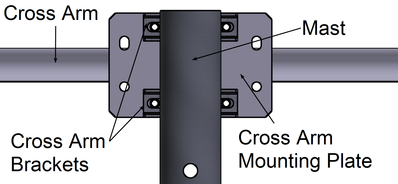
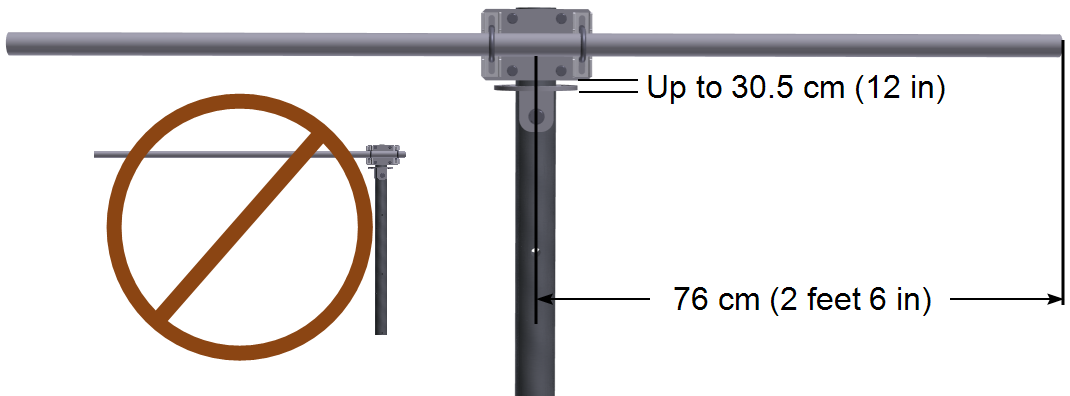
Install the cross arm up to 30.5 cm (12 inches) from the guy collar, centered on the mast. Adjust the guy collar as needed to minimize the distance as much as possible. Tighten the cross arm nuts to 9.6 N•m (85 lb•in; 7 lb•ft).
8. Install the Guy Wires on the Mast
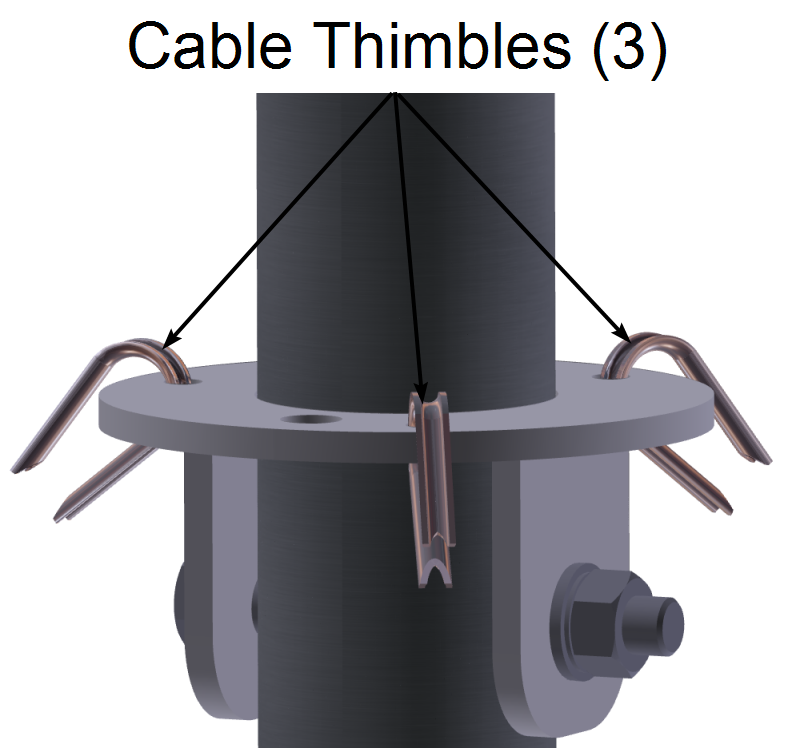
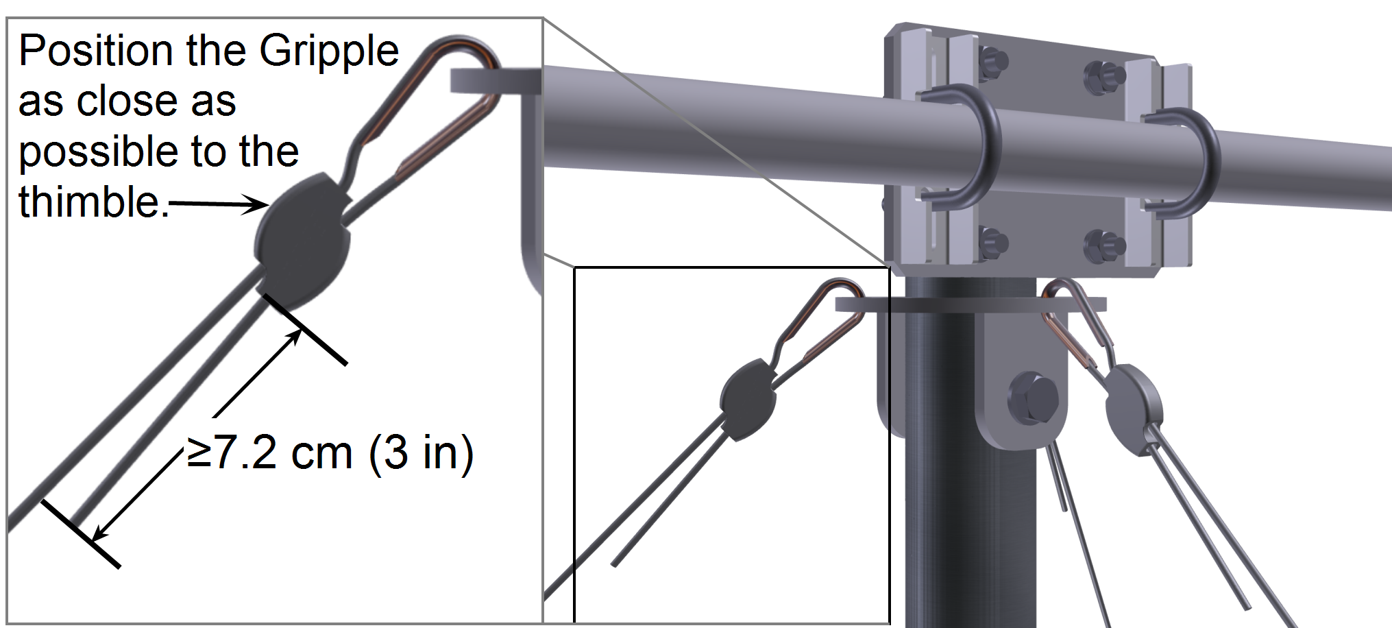
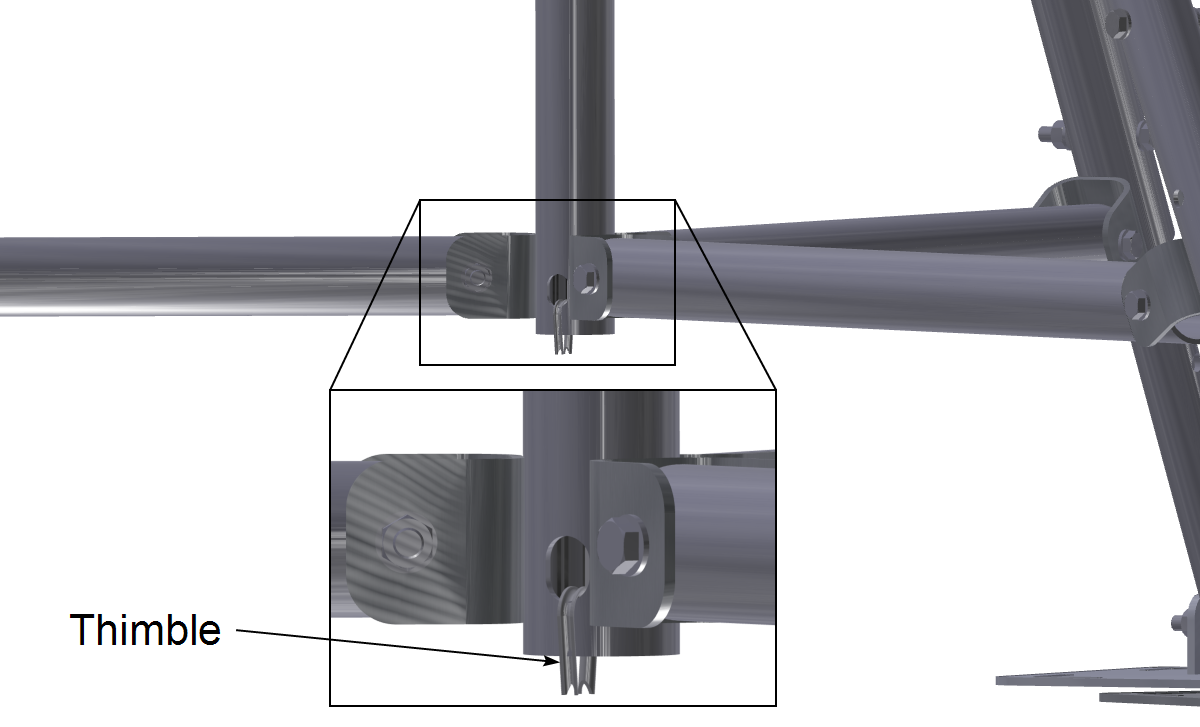
Insert a cable thimble into each of the cable holes in the guy wire fitting.

 Warning: The cables are stiff, corrosion resistant wire rope. Wear gloves and safety goggles when handling them.
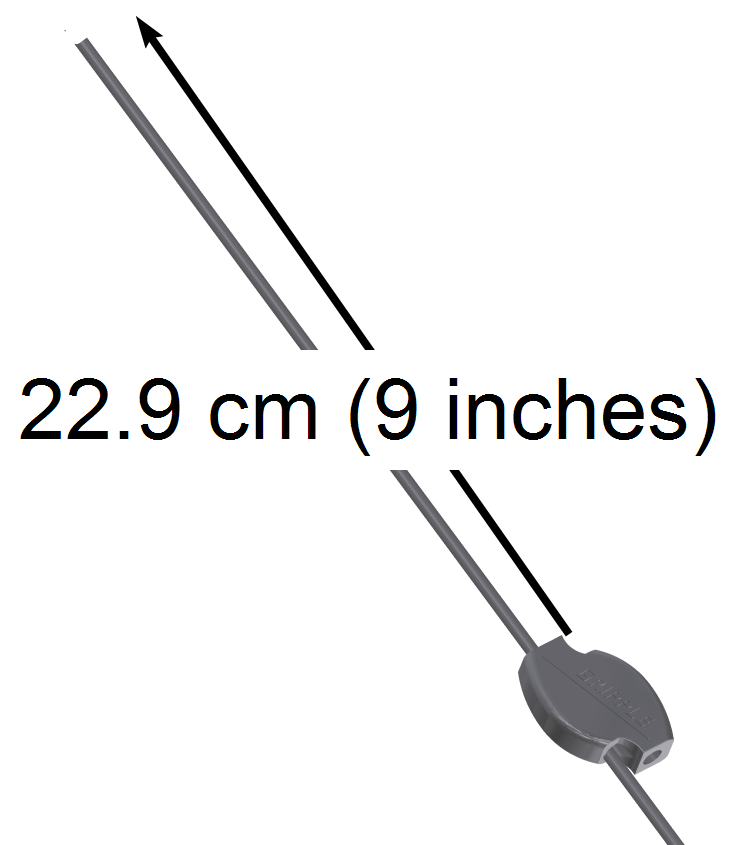
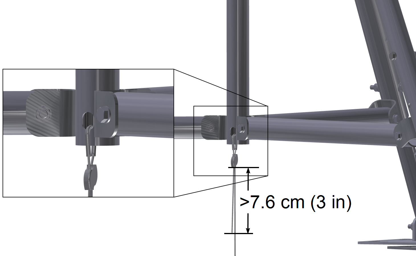
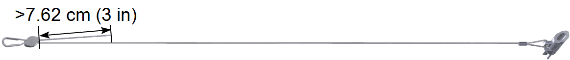
Then, insert about 22.9 cm (9 inches) of the cable through the Gripple® according to the arrows on the Gripple. To release the Gripple see Tighten the Guy Cables.
Route the cable around the thimble, through the guy wire fitting, and secure it through the other side of the Gripple. The cable should extend at least 7.6 cm (3 in) past the Gripple. Repeat this for each guy wire.
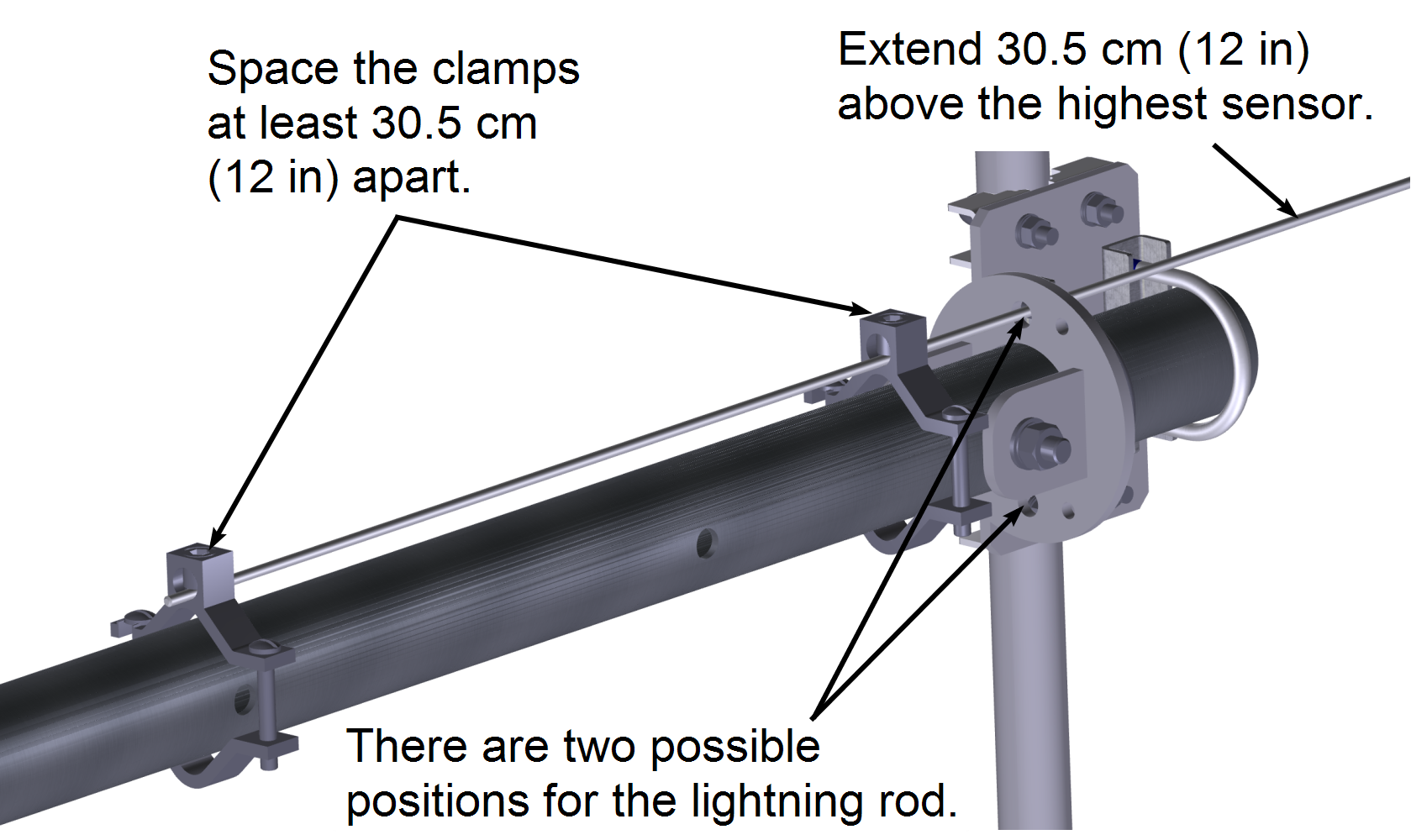
Install two lightning rod clamps as shown below. Attach the lightning rod to the mast with the two clamps. Use an 8 mm hex key to tighten the lightning rod.
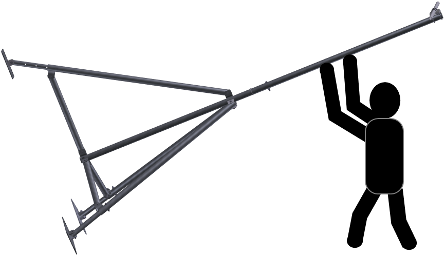
10. Raise the Tripod
Prior to raising the tripod, consider access to the site, the position of the cross-arm with respect to expected orientation of sensors, and wind direction. Set two legs in position and lift the mast until the tripod is in the vertical position. Enlist the help of an assistant if needed.
Anchor the Tripod
11. Drive the Mast Anchor into the Ground
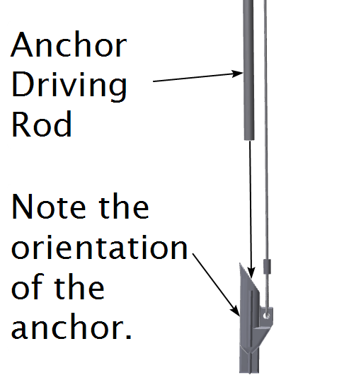
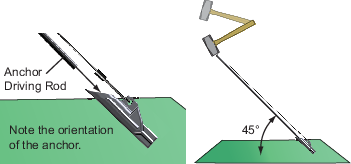
The earth anchor is to secure the mast to the ground. Think ahead about the position of the tripod—or even set the tripod in position, then identify the point on the ground where the anchor should be driven. Position the anchor so the cable will lead to the mast anchor attachment point. Set the tripod aside and drive the anchor. Note: Do not attach the mast anchor to the mast yet.
Warning: Read the notes on site selection (see Site Selection) before determining the final location for the tripod.
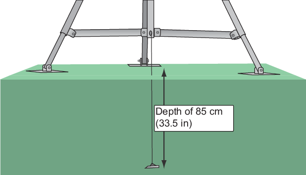
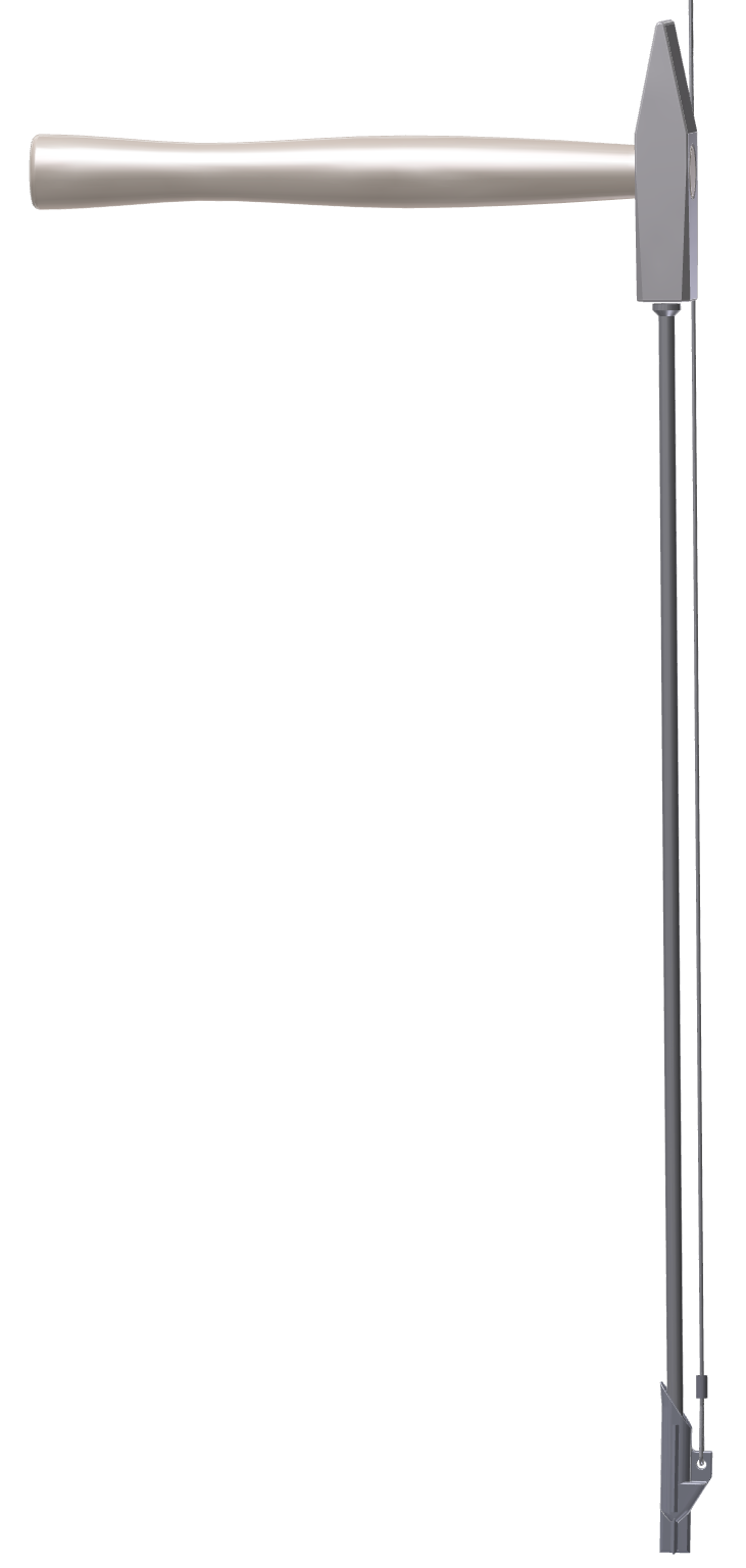
Use the 91.4 cm (36 inch) driving rod, drive the anchor to a depth of 85 cm (33.5 inches).
Warning: The cables are stiff, corrosion resistant wire rope. Wear gloves and safety goggles when handling them.
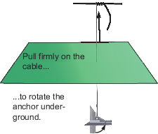
When setting the earth anchor, the cable will give several centimeters (~1 inch) when the anchor rotates underground.
Caution: When installed in suitable soil (see Soil Conditions), the tripod can withstand a 161 kph (100 mph) wind while supporting a load. If soil conditions deviate from those described here, take measures to ensure that the mast anchor can withstand 392 kg (864 lbs) of upward force in order to ensure that the tripod will meet the wind and load specifications.
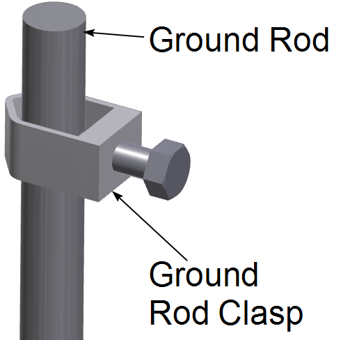
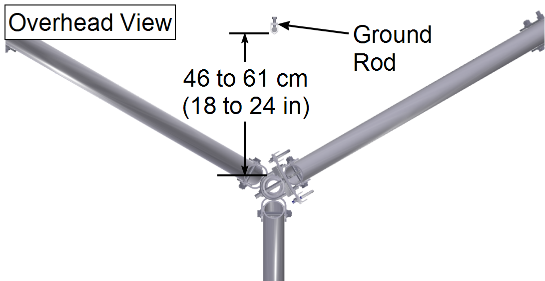
Position the ground rod 46 to 61 cm (18 to 24 in) from the mast/earth anchor. Drive it into the ground with a hammer or post driver, leaving about 10 cm (4 in) above the ground.
Note: Slide the ground rod clasp on the ground rod prior to driving the rod into the ground. The tip of the ground rod may become deformed as it is driven, making it impossible to install the ground wire clasp afterwards.
Move the tripod into the desired position and use a torpedo level to check the vertical orientation of the mast on adjacent sides. Adjust one or more legs until the level indicates that the mast is plumb.
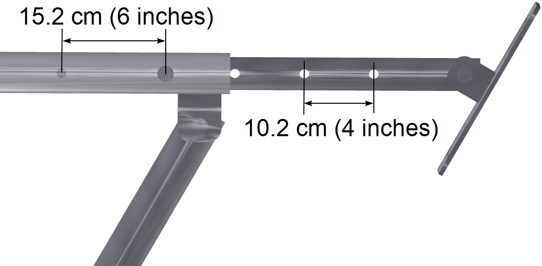
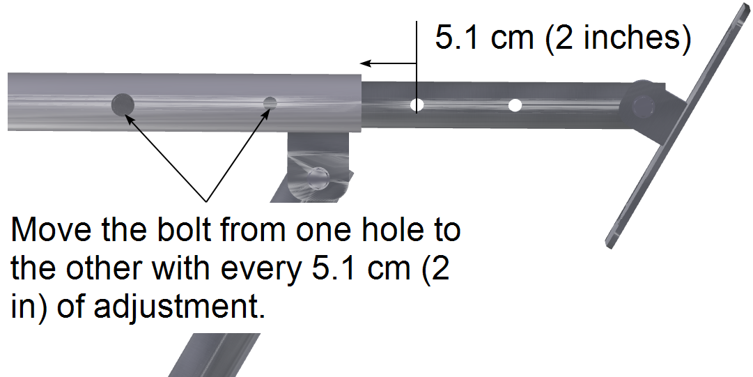
Each leg can be extended or retracted in 5.1 cm (2 in) increments. Each leg has 2 adjustment holes spaced at 15.2 cm (6 in), whereas each leg extension has 6 adjustment holes spaced at 10.2 cm (4 in).
Warning: It may not always be possible to plumb the tripod mast with the leg adjustments. The tripod should not deviate more than 2.3° from true vertical (approximately 15.2 cm (6 in) of deviation at the top of the upper mast). Make sure your experiment objectives will not be adversely affected by the deviation from plumb. If the mast deviates from vertical, it should lean toward the uphill side. Make sure the feet - especially the downhill feet - are firmly anchored on solid ground (see Install the Foot Stakes).
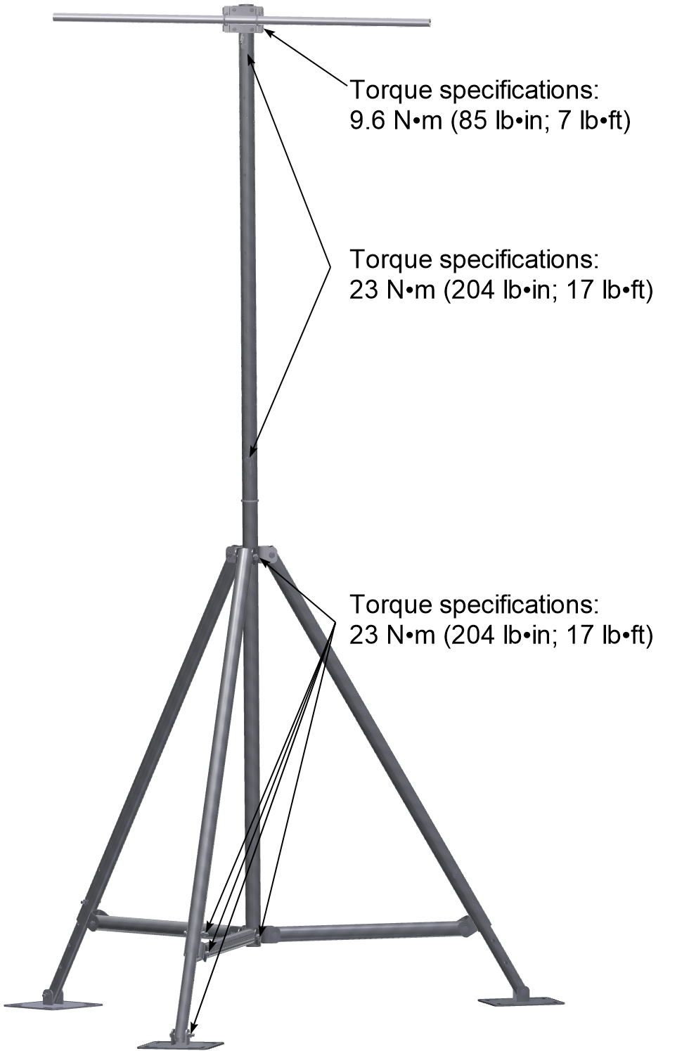
Tighten the nuts and bolts on the legs, leg extensions, leg braces and feet to 23 N•m (204 lb•in; 17 lb•ft). If not adequately tightened in the previous steps, tighten the cross arm nuts to 9.6 N•m (85 lb•in; 7 lb•ft), the guy wire fitting to 23 N•m (204 lb•in; 17 lb•ft), and the upper mast nut and bolt to 23 N•m (204 lb•in; 17 lb•ft).
15. Connect the Mast Anchor
Insert a thimble into the anchor point on the mast.
Warning: The cables are stiff, corrosion resistant wire rope. Wear gloves and safety goggles when handling them.
Insert 22.86 cm (9 in) of earth anchor cable into a Gripple® according to the arrows that are visible on the exterior of the Gripple device, loop it through a thimble, and then back into the Gripple. Tighten the cable securely around the thimble.
To tighten the cable, hold the Gripple in one hand and pull the end of the cable through the Gripple. Coil any extra cable and secure it with zip ties. To release the Gripple see Tighten the Guy Cables.
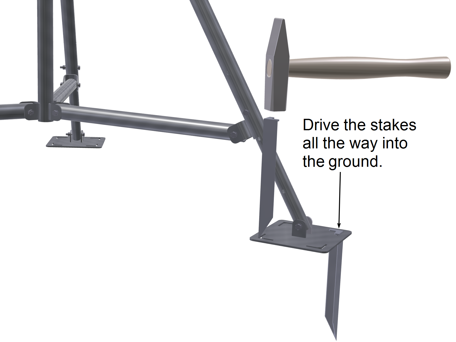
Foot stakes serve to secure the feet and prevent them from moving on the ground. Using a hammer, drive two stakes into opposite corners of each foot. It is normal for the top of each stake to deform when it is driven. Note: Before installing the stakes, be sure the tripod is positioned exactly as desired and that the mast is vertical (see Plumb the Mast). Adjustments are more difficult after the foot stakes have been installed.
Caution: Each foot must withstand 275.8 kg (608 lbs) of lateral load and 392.8 kg (886 lbs) of downward load in order to meet the 161 kph (100 mph) wind load specification. These conditions are met if the tripod foot stakes are installed as described in this manual. If your site conditions deviate from those described here (seeSoil Conditions) select an alternate site.
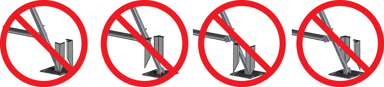
Warning: The stakes should be driven into opposite corners of each foot for maximum stability. Never drive the anchors into adjacent corners.
Note: If the soil pH is above 8.5 or below 4.5 (e.g., non-draining clay-organic and fertilized fields) the aluminum that is in contact with the soil will corrode faster. For more information see Soil Conditions.
17. Install the Guy Anchors and Wires
The three remaining earth anchors are to secure the guy wires. Prepare each anchor by inserting the cable into a Gripple® connector according to the arrows printed on the connector. Make a loop around a thimble and insert the other end of the cable into the Gripple. Pull at least 7.62 cm (3 inches) of cable through the Gripple. Assemble the earth anchors, thimble and Gripple as shown.
Warning: The cables are stiff, corrosion resistant wire rope. Wear gloves and safety goggles when handling them.
Warning: Check to be sure that there are no underground utilities or unexploded buried ordnance prior to installing the earth anchors. Failure to do so could result in severe bodily injury, death and/or damage to equipment.
Caution: In order to meet the 161 kph (100 mph) wind load specification, each anchor must withstand 180.1 kg (397 lbs) of force. The supplied anchors do this, provided that the tripod is installed in the recommended soil conditions. If soil conditions at your site deviate from those described here (see Soil Conditions) select an alternate site.
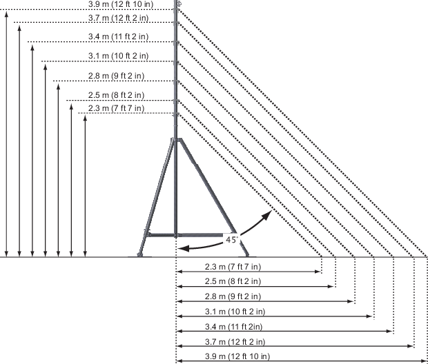
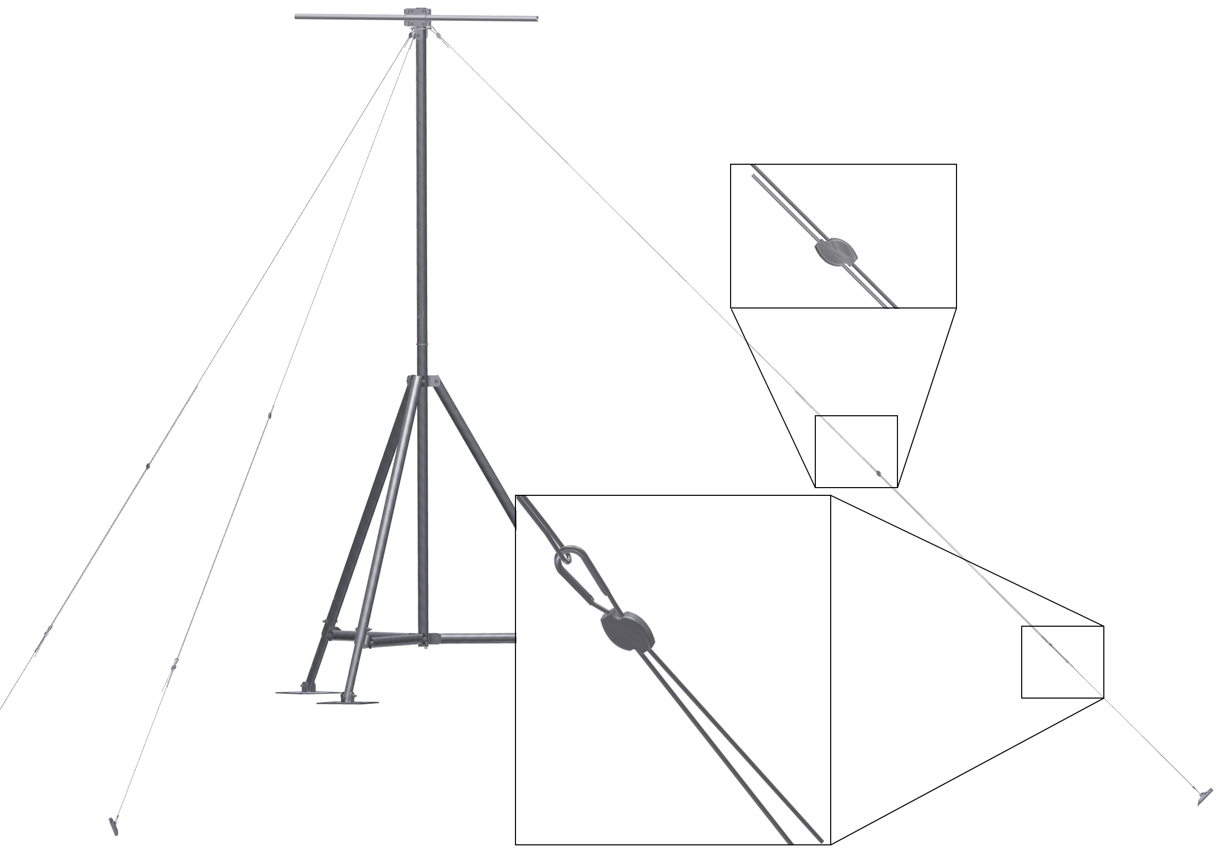
Guy wires should be positioned at a 45° angle between the mast and earth anchors, as shown in the following figure. Vertical distances are between the ground and the top of the guy wire fitting. Horizontal distances are from the mast to the earth anchor. Determine the location for each earth anchor with the tripod in its final position.
Use the Earth anchor driving rod and a sledge hammer to drive each anchor to a depth of 85 cm (33.5 inches). Each anchor should be driven at a 45° angle along the same axis as the corresponding guy wire.
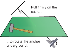
Each anchor must be set after it is driven. Insert the driving rod into the cable thimble and pull firmly on the cable. You will feel the cable pull out several centimeters (about an inch) when the anchor rotates in the ground and locks in place.
Finish installing each guy wire by routing the guy cable through one side of a Gripple® according to the arrows on the device, through the loop at the end of the guy anchor, and back through the Gripple, pulling at least 7.6 cm (3 in) through the Gripple. Grab the Gripple and pull to get the cable snug. Coil any extra cable and secure it with cable ties.
Warning: The cables are stiff, corrosion resistant wire rope. Wear gloves and safety goggles when handling them.
Warning: Do not over tighten the guy wires. When the guy wires are properly tightened there will be slight slack in the cable. Excessively tightened guy wires apply a load to the tower, diminishing its ability to support the sensors.
Note: Position the upper guy wire Gripple as high up the cable as possible. When it is necessary to remove the cable, you can cut the cable close to the Gripple, preserving a significant portion of the cable for reuse.
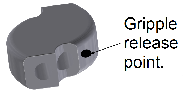
Note: To release the Gripple, locate the Gripple release key in the Guy Wire Kit. Identify the hole in the Gripple, which can be found near either one of the cable insertion points.
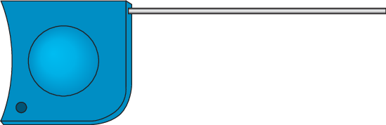
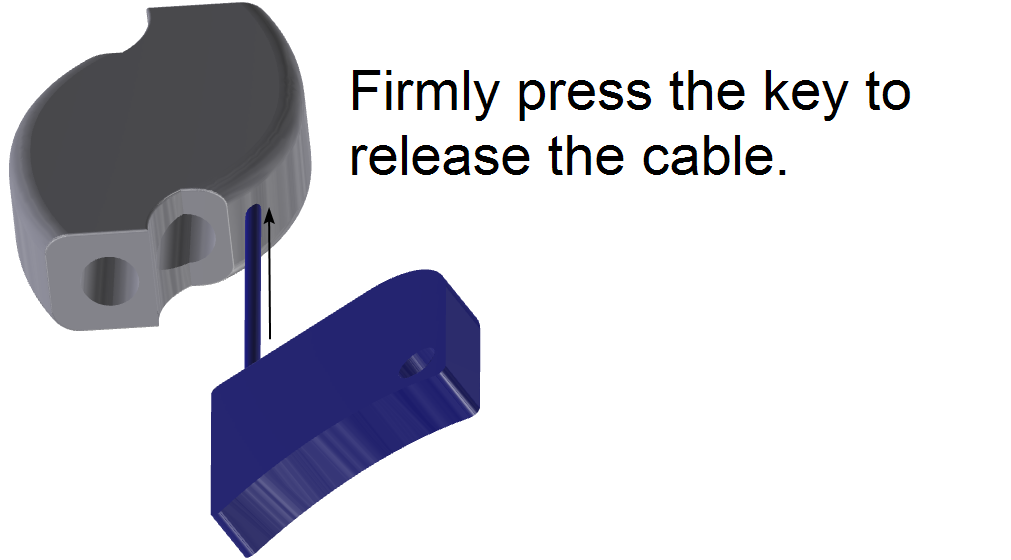
Insert the Gripple release key into this hole and press firmly. If there is tension on the cable it may be helpful to relieve the tension. When the Gripple release key has been pressed with sufficient pressure, the Gripple will release the cable, allowing you to move the cable freely within the Gripple.
The ground wire connects the the ground rod and the mast.
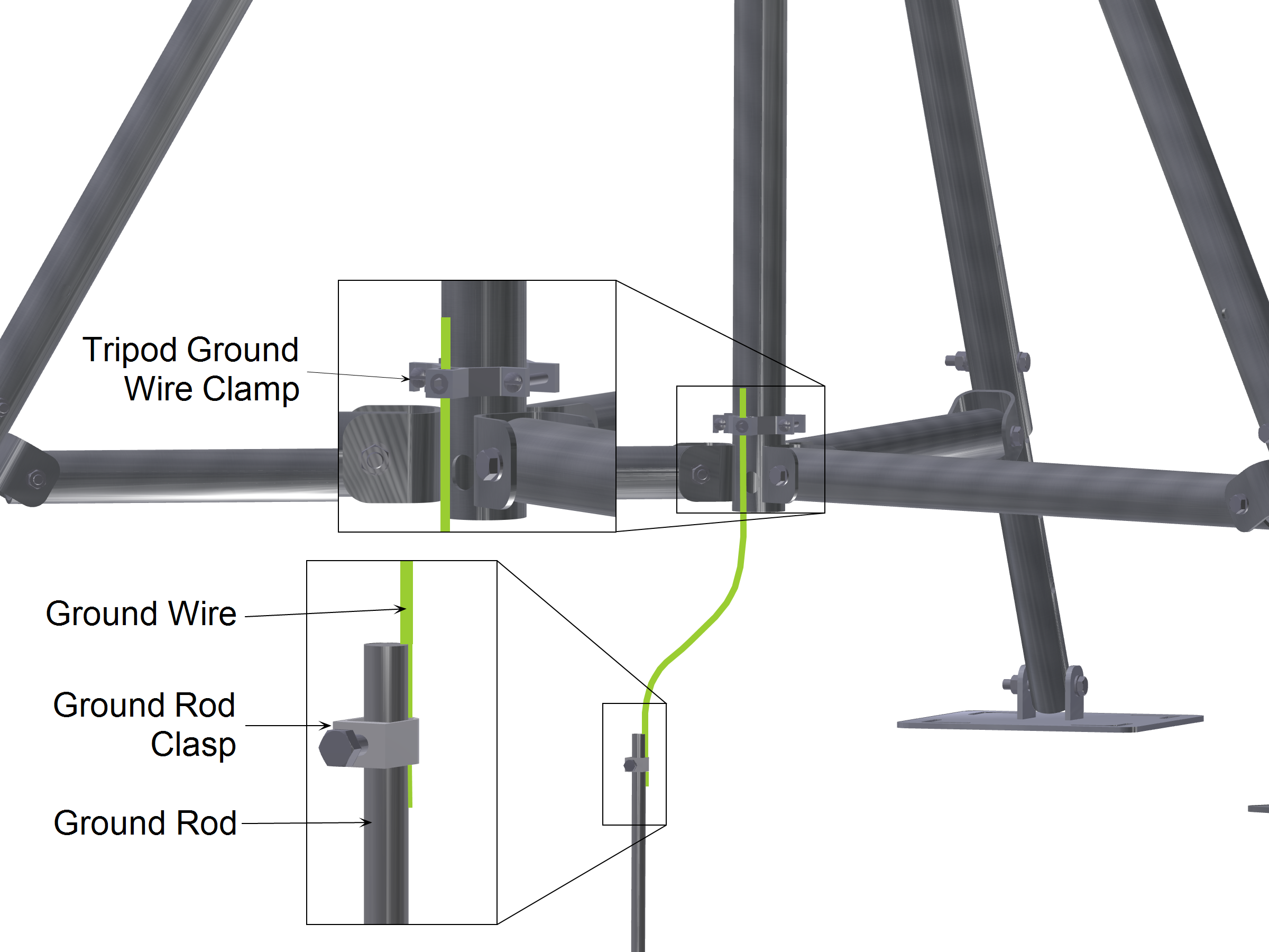
Note: The bolt in the ground rod clasp is a torque-limiting bolt that will break if it is overtightened. Tighten it snugly onto the ground rod and ground wire.
20. Verify the Stability of the Tripod
As a final step, verify the stability of the tripod to ensure it is assembled properly.
- Double check the vertical orientation of the tripod using a level (see Plumb the Mast).
- Check each nut and bolt to verify that each is tightened to the torque specification (see Torque the Nuts and Bolts).
- Check the tightness of the guy cables and mast anchor. Adjust as necessary (see Tighten the Guy Cables).