General Information
Safety Information
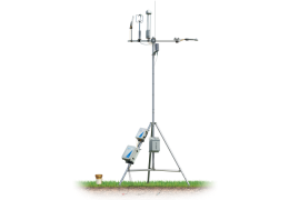
The 7900-300 Heavy Duty Adjustable Tripod has been designed to be safe when operated in the manner described in this manual. The safety of this product cannot be guaranteed if the product is used in any other way than described in this manual. Be sure to read and understand all of the safety information included in this manual.
The equipment includes the following markings:

|
This symbol indicates that the user must read the instruction manual prior to assembling or using the tripod. |
|
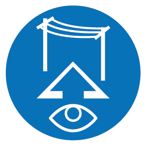
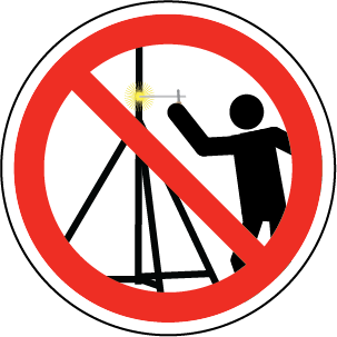
This symbol indicates that it is mandatory to check for overhead power lines prior to assembling the tripod. |
|
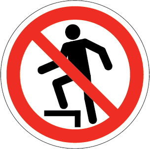
This symbol indicates that the tripod is not suitable for stepping or climbing. |
|
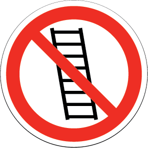
This label indicates that users should never lean a ladder against the tripod. |
Precautions
Warning: Read all the instructions in this manual prior to assembling, moving, or disassembling the tripod.
Warning: Never cover or conceal the safety labels that are attached to the tripod. Doing so could lead one to fail to observe the safety warnings and sustain personal injury or damage to equipment through the use of the tripod.
Warning: Assembly of the 7900-300 Adjustable Heavy Duty Tripod should be carried out with a minimum of two people. Attempts to assemble the tripod with an insufficient number of people could lead to personal injury.
Caution: Each stake must withstand 275.8 kg (608 lbs) of lateral load and 392.8 kg (886 lbs) of downward load in order to meet the 161 kph (100 mph) wind load specification. These conditions are met if the tripod is installed as described in this manual. If your site conditions deviate from those described here (see Soil Conditions) select an alternate site.
Warning: Conduct a pre-installation site visit to determine proper soil composition for a successful tripod installation. Acceptable soil conditions (see Soil Conditions) should be studied in advance of the pre-installation trip.
Warning: The tripod is not suitable for installation on solid rock, soils that are composed of a rocky substrate, or other hard surfaces that will not allow installation of any of the following: earth anchors, foot stakes, or grounding rod. In these conditions the tripod may not meet the specifications described in the instructions and additional measures may be required to stabilize the tripod. If you have these conditions, consult with a local geotechnical engineer to determine whether soil at your site is suitable for the tripod.
Warning: The tripod may not be adequate for every situation depending on soil structure, maximum wind speeds experienced at the site, mast height, or wind load from the instrumentation. If uncertain, seek the advice of structural and geotechnical engineers.
Warning: It may not always be possible to plumb the tripod mast with the leg adjustments. The tripod should not deviate more than 2.3° from true vertical (approximately 15.2 cm (6 in) of deviation at the top of the upper mast). Make sure your experiment objectives will not be adversely affected by the deviation from plumb. If the mast deviates from vertical, it should lean toward the uphill side. Make sure the feet - especially the downhill feet - are firmly anchored on solid ground (see Install the Foot Stakes).
Warning: Never lean a ladder against the tripod. Doing so may cause structural failure and result in severe injury, death, and/or damage to equipment.
Warning: Never step on the legs or leg braces; and never attempt to climb the tripod. Doing so may result in severe injury, death, and/or damage to equipment.
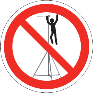
Warning: Do not hang from the tripod or cross arm. Doing so may cause the tripod to fall or fail, and result in severe injury, death, and/or damage to equipment.
Warning: Never weld the tripod or attach a bracket that serves to support a climbing apparatus. Doing so will compromise the strength of the tripod and may result in injury, death, and/or damage to equipment.
Site Selection
Careful site selection will provide simpler setup and ensure that your sensors collect high-quality, representative data. The site should accommodate the tripod and guy wires without interfering with any of the tripod components. The feet require an unobstructed area with a 2.54 m (8 ft 4 in) diameter. The guy wires require an area with an 8 m (26 ft 3 in) diameter.
As a general rule, disturb the site as little as possible. Prior to assembling the tripod, remove any woody brush or tall plants that are in the way of the tripod feet and guy wires.
Warning: It is dangerous to install the tripod close to overhead power lines, buried power lines, underground gas lines, or unexploded ordnances. Keep a minimum distance of at least 2 times the height of the tripod (including the lightning rod) between the tripod and nearest overhead line. Prior to installing the ground rod or anchors, be sure that there are no underground utilities, power lines, unexploded ordnances, or other installations at your site.
Soil Conditions
The Heavy Duty Adjustable Tripod can be adequately supported in “average” soil. “Average” soils are defined as stiff silts and clays containing up to 50% sand and gravel and having blow counts (N) of 8 to 16 per ASTM D 1586 and unconfined compressive strengths of 1500 to 3000 pounds per square foot. This soil would be defined as Class 6 in accordance with the literature of Foresight® Products, the manufacturer of the Duckbill® Model 68 earth anchors intended for use with the tripod. The tripod is not to be installed in clean sands or gravels.
Aluminum that is in contact with soil with a pH above 8.5 or below 4.5 (e.g., non-draining clay-organic and fertilized fields) will corrode faster. If your site has soil that meets these conditions take measures to physically separate the aluminum feet from the soil (e.g., place a sheet of sturdy plastic from a heavy duty trash bag between the metal and soil) and check the condition of the feet and stakes regularly.
Warning: The tripod is not suitable for installation on solid rock, soils that are composed of a rocky substrate, or other hard surfaces that will not allow installation of any of the following: earth anchors, foot stakes, or grounding rod. In these conditions the tripod may not meet the specifications described in the instructions and additional measures may be required to stabilize the tripod. If you have these conditions, consult with a local geotechnical engineer to determine whether soil at your site is suitable for the tripod.
Loading the Tripod
Load the tripod according to the weights and frontal areas given below.
Warning: The guy kit, earth anchors, and foot stakes must be installed to meet the tripod specifications. If these components are not installed, the tripod may fall or fail, resulting in injury, death, and/or damage to equipment.
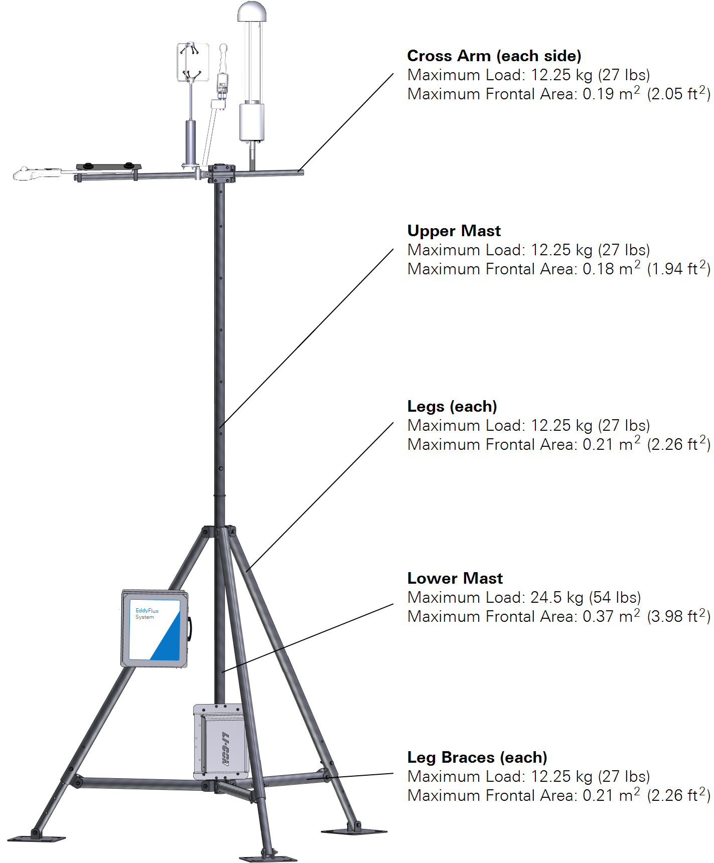
| Tripod Component | Maximum Load | Maximum Frontal Area |
|---|---|---|
| Cross Arm | ||
| Left | 12.25 kg (27 lbs) | 0.19 m2 (2.05 ft2) |
| Right | 12.25 kg (27 lbs) | 0.19 m2 (2.05 ft2) |
| Masts | ||
| Upper | 12.25 kg (27 lbs) | 0.18 m2 (1.94 ft2) |
| Lower | 24.5 kg (54 lbs) | 0.37 m2 (3.98 ft2) |
| Legs | ||
| Leg 1 | 12.25 kg (27 lbs) | 0.21 m2 (2.26 ft2) |
| Leg 2 | 12.25 kg (27 lbs) | 0.21 m2 (2.26 ft2) |
| Leg 3 | 12.25 kg (27 lbs) | 0.21 m2 (2.26 ft2) |
| Leg Braces | ||
| Leg Brace 1 | 12.25 kg (27 lbs) | 0.21 m2 (2.26 ft2) |
| Leg Brace 2 | 12.25 kg (27 lbs) | 0.21 m2 (2.26 ft2) |
| Leg Brace 3 | 12.25 kg (27 lbs) | 0.21 m2 (2.26 ft2) |
| Total: | 134.75 kg (297 lbs) | 2.19 m2 (23.58 ft2) |