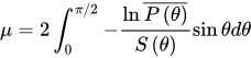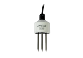
Configuring the LI-300 (analog)
The LI-300 provides data as analog signals. It features a single default configuration that is suitable for most soil types. You simply need to connect the leads to a suitable data logging device and scale the datalogger channels to associate the voltages with soil moisture values. All LI-300 probes have the same response.
Connecting the LI-300 to an analog data acquisition device
The LI-300 provides data as analog voltage. It features a four-wire cable with assignments given in Table 3‑1. The power supply voltage should be slightly above 3 volts. If you are using a long cable, expect the voltage to drop due to the cable length. In cases like this, be sure the power supply voltage is high enough to account for attenuation that results from the long cable.
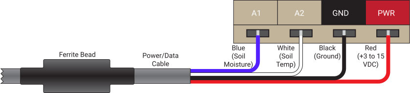
Data are logged on two channels. One channel reports soil moisture (blue wire, voltage range of +0.5 to +2.5 V). The other channel reports soil temperature (white wire, voltage range of +0 to +2.5 V). Table 3‑1 gives wire colors and functions.
| Color | Function |
|---|---|
| Black | Ground |
| Red | Power (+3.05 to 15 VDC) |
| Blue | VWC Soil Moisture Signal (+0.5 to 2.5 V) |
| White | Soil Temperature Signal (+0 to 2.5 V) |
Computing VWC and soil temperature
Analog voltages representing VWC and soil temperatures are non-linear. Voltages for both signals can be converted using the appropriate equation. Conversions can be carried out on the datalogger or after the voltages are recorded. Use the following polynomials and equations.
VWC
The analog VWC signal covers the full range of soil moisture across the range of 0.5 to 2.5 volts. 0.5 V is the reading in air; 2.5 V is the reading in water. The signal is converted to VWC by applying equation 3‑1 with the appropriate coefficients in Table 3‑2.
With Vcal as the calibrated output, the VWC equation is

Soil temperature
The soil temperature signal covers a temperature range of −40 to 70 °C across a voltage range of 0 to 2.5 V. The signal is converted by applying the following equation.