Installing the Leaf Trace Gas Integration System
Two hardware components will be installed: the interface box mounts to the console and the manifold mounts to the LI-6850 head. Several tubes and a cable connect the components. In addition, the firmware must be updated.
The interface box
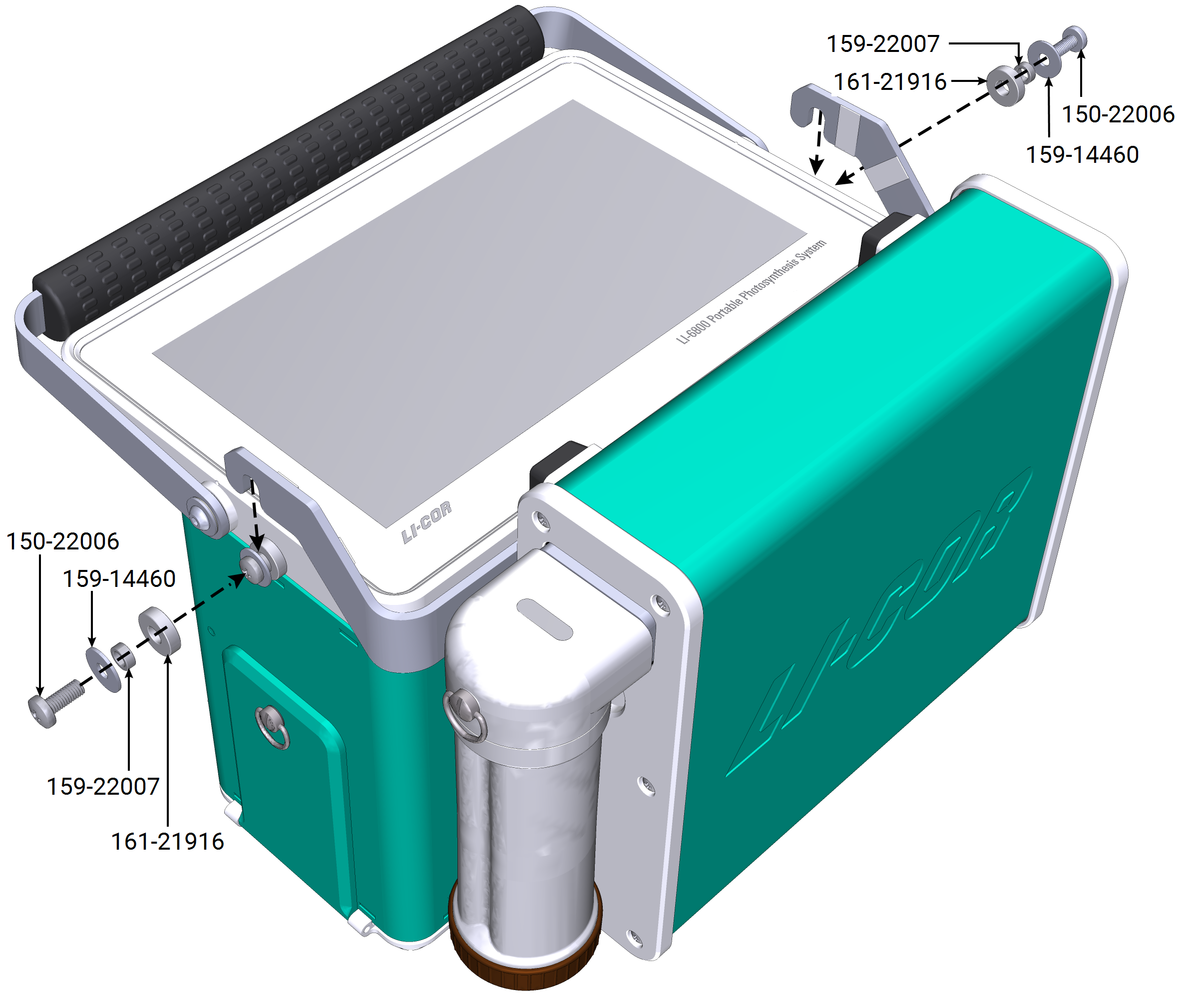
The TGA interface box attaches to the side of the console on retainers that are threaded into the holes used for the carrying harness. A Phillips #2 screwdriver (there is one in the LI-6800 spare parts kit) is the only tool needed. Figure 12‑4 shows the required retainer hardware with correct orientation and order of attachment. Once the two retainers are installed, the arms of the interface box rest on the small spacer.
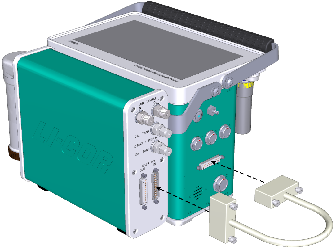
In order to power the pump and operate valves of the interface box, the DB25 cable (Figure 12‑5) needs to be attached between the LI-6800 console USER I/O port and the USER I/O IN connection on the interface box.
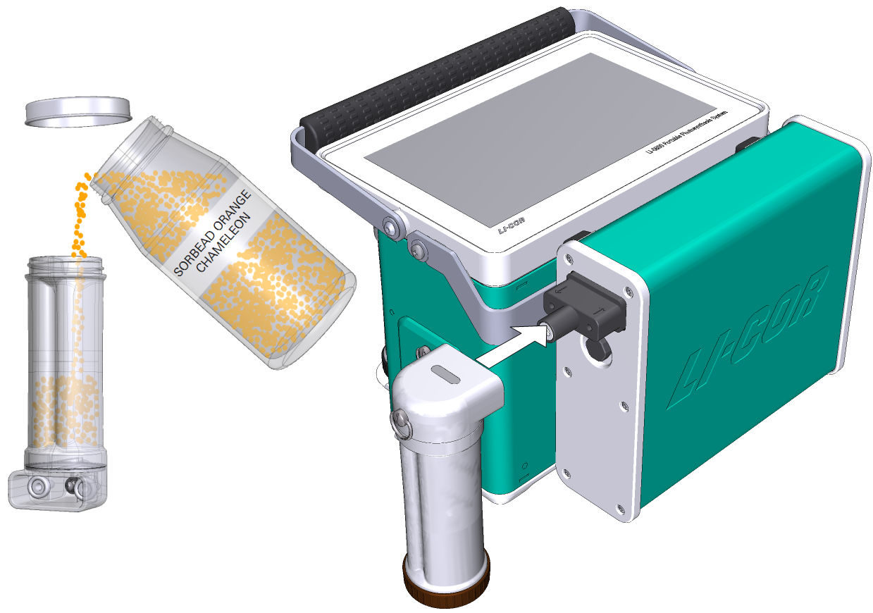
Fill the column with fresh Sorbead ORANGE Chameleon (622-16951) indicating silica gel beads and install it on the interface box.
The head manifold
To mount the manifold to the LI-6850 head:
-
Remove the bottom cover from the sensor head, unplug the leaf temperature thermocouple(s), external quantum sensor, and remove the screen filters for ports A and B, if present.
-
Attach the exhaust manifold to the sensor head IRGA exhaust ports, as shown in Figure 12‑6.
First, check to be sure that each connection screw has an O-ring. Then use a slotted screwdriver to alternately tighten the connection screws to the threaded ports labeled A and B on the sensor head until both sides are tight.
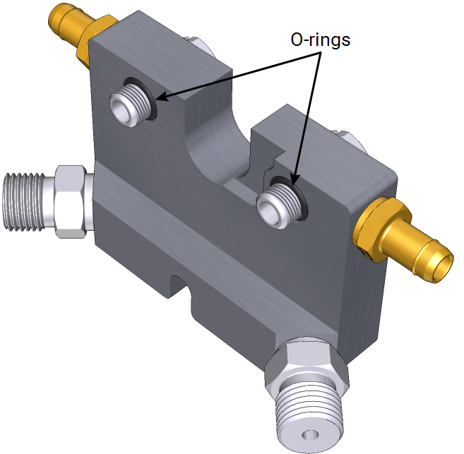
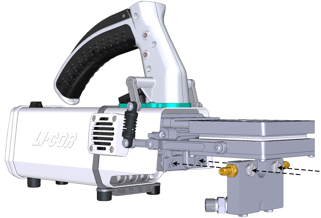
Figure 12‑6. Be sure both O-rings are present and then mount the manifold to the A and B exhaust ports under the chamber. -
Reconnect the leaf temperature thermocouple(s) and external quantum sensor, feeding the wire through the slot at the bottom of the manifold.
-
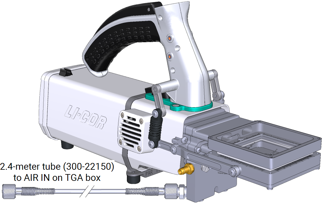
Connect the longer air hose to the exhaust port on the lower 'A' side on the exhaust manifold.
On the upper 'A' side, a 1/4" barb is provided on the over-blow of the manifold, through which excess flow from the LI-6800 is vented.
Air hoses
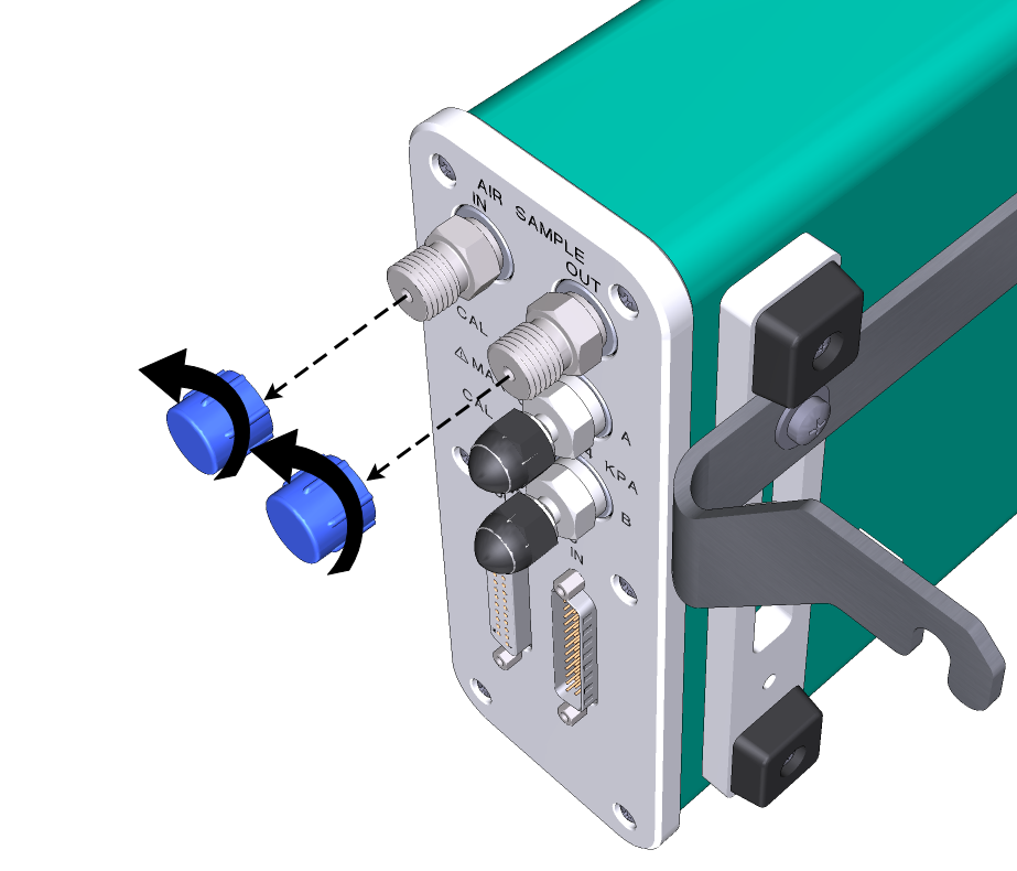
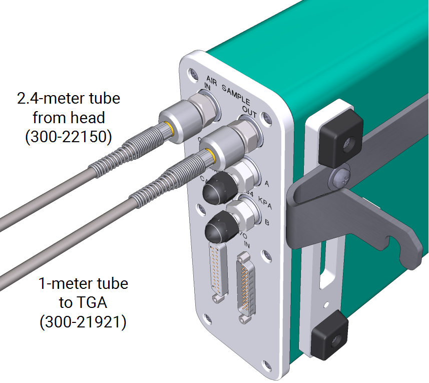
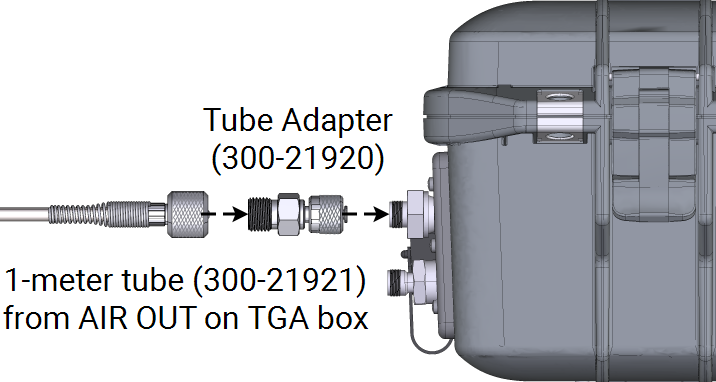
The longer air hose (2.4 m) is intended for use from the LI-6800 manifold to the interface box Sample IN port. Since this cable is of similar length to the LI-6800 power cables, it can be routed in the sheath with those cables if desired. The shorter air hose (0.9 m) connects the interface box Sample OUT port and the inlet of the TGA (IN port on the TGA). The adapter (300-21920) is required for this connection.
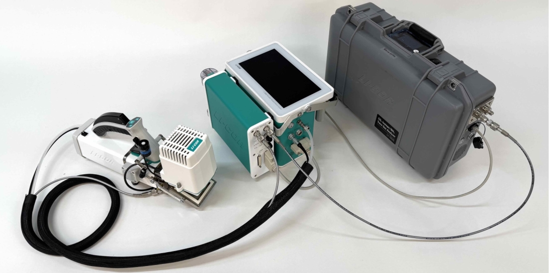
Tighten the connectors by hand until snug. No tools are needed. The assembled system without external calibration tanks is shown in Figure 12‑7.
Calibration tanks
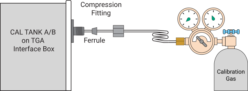
Calibration tanks can be connected and used to set zeroes and/or spans on the TGA. These operations can be performed manually by the user or automated as part of background programs. Tanks connect to tank ports using 1/8" OD tubing and compression fittings (included). Tighten the compression fitting to hand-tight and then another one full turn.
Caution: Tank outlet pressure must be regulated to < 5 PSI. A low-pressure regulator may be needed.
Ethernet cable
Communication between the LI-6800 and TGA must also be established to bring the TGA data stream into the LI-6800. Since both instruments communicate via Ethernet ports, one option is to directly connect them on their own network, by attaching an Ethernet cable (included) directly between the instruments. Alternatively, both instruments can be placed on the same local network via separate Ethernet cables to an Ethernet switch (not included). An advantage of the latter arrangement is that both instruments are still accessible by other devices on the network, such as your PC.
Installing the software
The LI-6800 console must have Bluestem version 2.2.1 or later installed. The latest software can be found at Software Downloads.
Use the Config Extras Manager
TGA support is a "built-in" configuration extra in Bluestem 2.2.x. Figure 12‑8 illustrates how to install TGA support, starting from the Start Up > Configuration > Manage Extra Configs window.
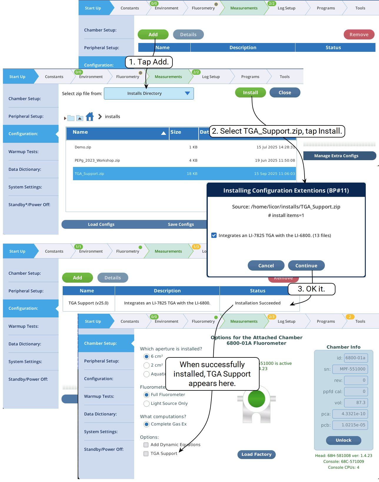
Subsequent LI-6800 software updates that contain updates to the TGA Support module will be implemented (re-installed) automatically on start up, if TGA Support has been installed already.
Enabling and disabling
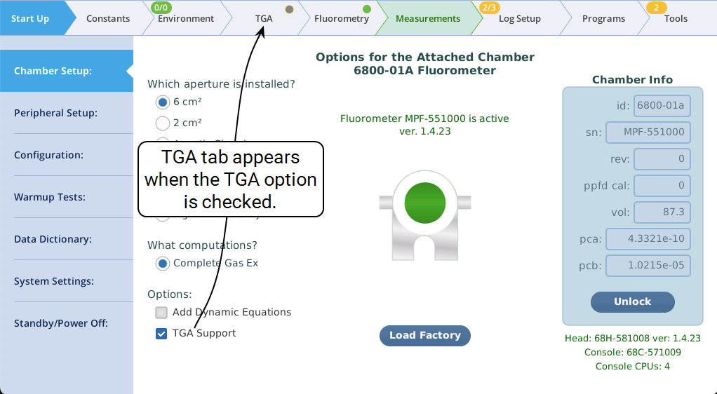
Once the TGA Support config extra is installed, it can be enabled and disabled via a check box on the Chamber Setup screen (Figure 12‑9). No attempt is made to restrict the TGA Support availability based on current configuration (soil chamber, aquatic chamber, etc.). Case in point: even though using dynamic equations (non-steady state) seems mutually exclusive with the steady state (and long averaging times) requirements for getting sample and reference values from the TGA, we nevertheless allow both options at the same time, leaving you free to experiment and innovate.
Uninstalling
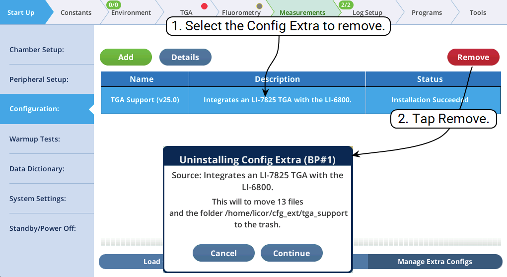
To remove TGA Support entirely from the interface, you can uninstall it (Figure 12‑10). Since it is a "built-in" config extra, it does remain available for re-installation (Figure 12‑8) whenever you wish.