Installing the LI-710
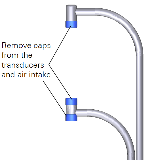
Remove the caps that cover the transducers and air intake before powering on the LI-710 (see Figure 3‑1).
Deployment considerations
The LI-710 can be deployed as a stand-alone sensor, in a weather station, or as part of an eddy covariance flux station. There are a few considerations that will help ensure that the data you collect accomplishes your measurement goals.

Measurement area
Measurements from the LI-710 represent a land area immediately surrounding the sensor. Therefore, you should install the sensor in the middle of the area-of-interest. Large open areas are ideal. For crops and grasslands, the middle of the field is ideal.
If you are unsure where to install the sensor, put it in the middle of the area you want to measure. If you have to choose a side, choose the side that is downwind of the prevailing wind over the area-of-interest.
Note: If the LI-710 is installed in the middle of the area-of-interest, footprint information is not critical for interpreting the data. In cases where the footprint is required, you should collect horizontal wind information and calculate the footprint using your own methods. Ideally, the deployment will be such that there is no need to determine the footprint.
Distance from surrounding elements
To ensure that the LI-710 measures a representative area-of-interest, install it above or as far as possible from large obstructions that affect the flow of wind, such as buildings or large solitary trees. Small elements, such as instruments on a weather station, are not problematic, although you should allow clearance of two meters or more, if possible.
Caution: If deploying the LI-710 near a cellular antenna, position the antenna at least two meters away from the LI-710 to reduce the risk of electromagnetic interference.


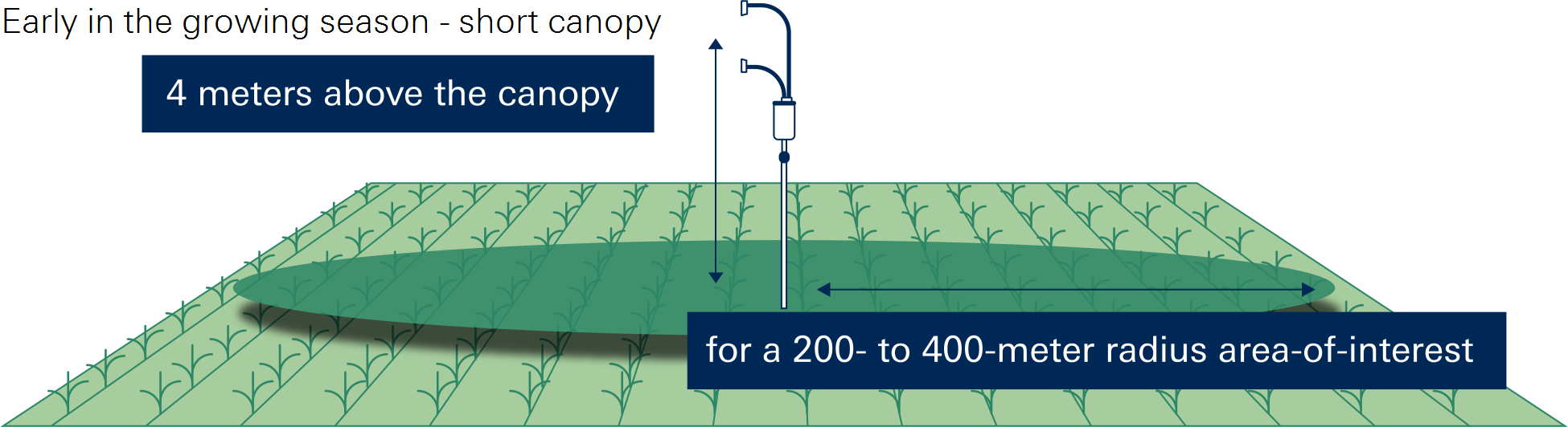
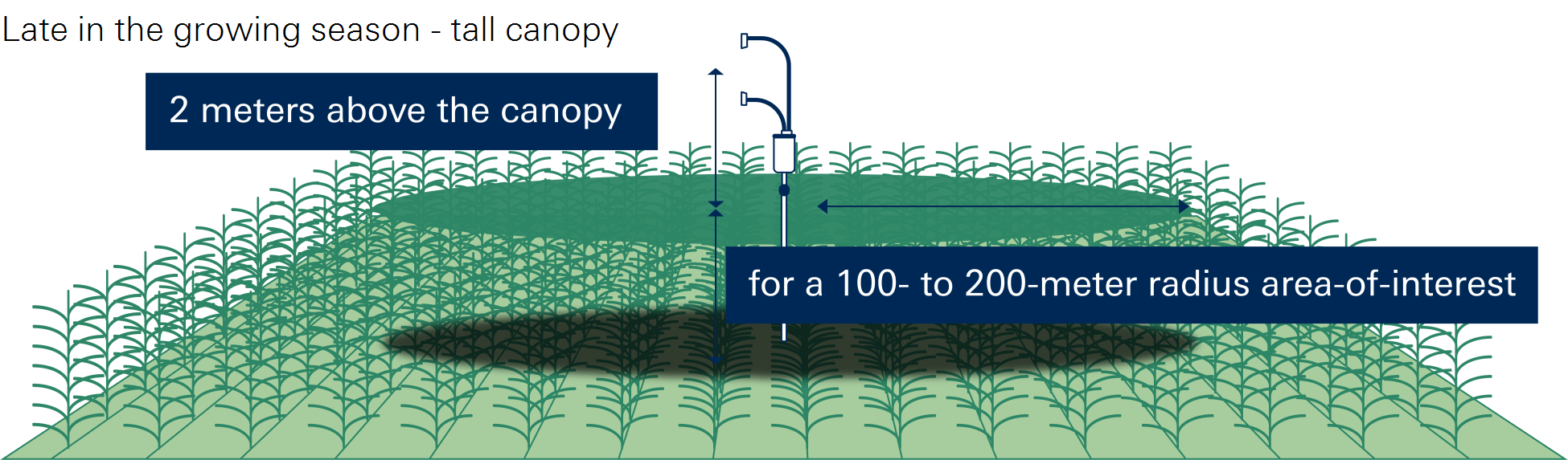
Height above the canopy
The measurement area represented by the LI-710 depends on its height above the plant canopy. In general, the LI-710 should be installed at least 3 m above the ground or at a height equal to twice the canopy height (2× canopy height).
For example, when mounted at a height of 4 m, the approximate fetch — the area influencing the measurement — extends to a radius of about 400 m around the LI-710 (see Figure 3‑3). All landscape elements within this radius can contribute to the measured evapotranspiration.
The LI-710 is designed for use over annual crops and orchards. For fast-growing canopies such as soybeans, sorghum (milo), wheat, flax, rice, corn, vegetables, and cotton, install the LI-710 3.5 m (for soybeans) to 5 m (for corn) above the soil surface before germination, providing a fetch of roughly 350–500 m.
As the crop grows, the distance between the sensor and canopy decreases, reducing the fetch. This condition is ideal — the measured area then corresponds closely to the field area of interest throughout the growing season. Alternatively, the LI-710 can be raised periodically during the season to maintain a consistent measurement height of approximately 2× the canopy height.

Over orchards and woodlands, which are characterized by partial to full canopy closure, the LI-710 should be at least 3 meters above the top of the canopy.

Terrain, slope, and tilt
You can expect good results as long as the sensor is within a few degrees of perpendicular to the slope of the area-of-interest. The grade can range from 0 to 10%. Measurements from the sensor are not highly sensitive to slopes up to 10° from level. The level application on many mobile phones is adequate to confirm that the tilt of the sensor matches the grade. Tilt from vertical is recorded in data group 2 (see Group 2: Air, humidity, and instrument information).


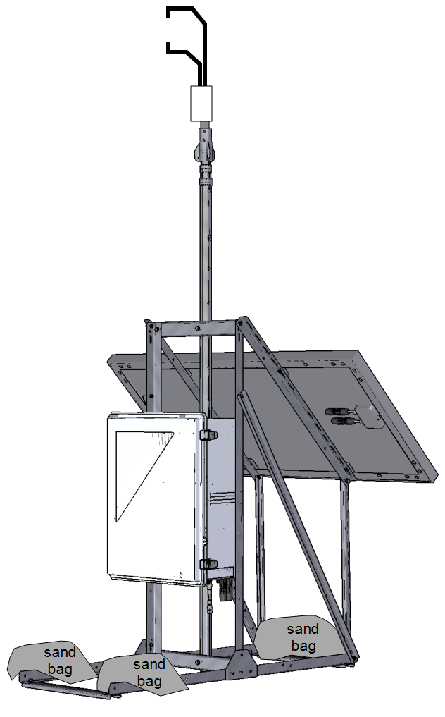
Deployment example
You have completed the hardware assembly. Take a moment to review the safety and stability of your installation and make any refinements. Then, install the soil probe and determine the measurement height of the LI-710.

Installing the soil probe
The soil probe can be installed at the surface or at a depth below the soil surface. Follow the installation instructions from Stevens. Place it in soil that is representative of the site, not under the shadow of the solar panel.
Determining the measurement height
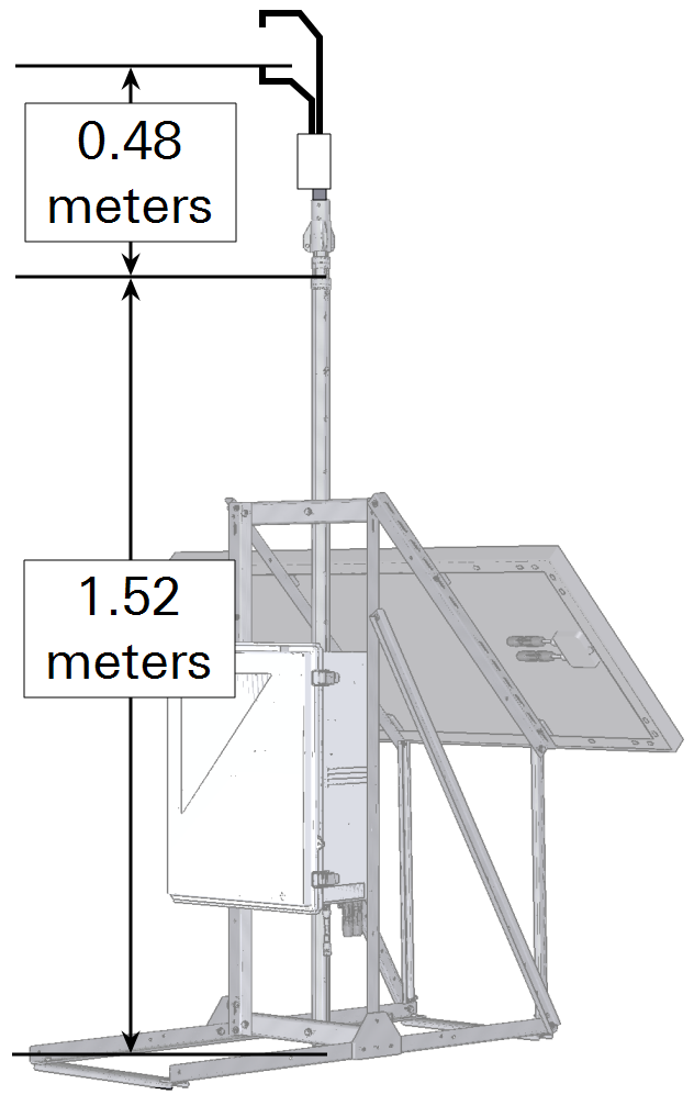
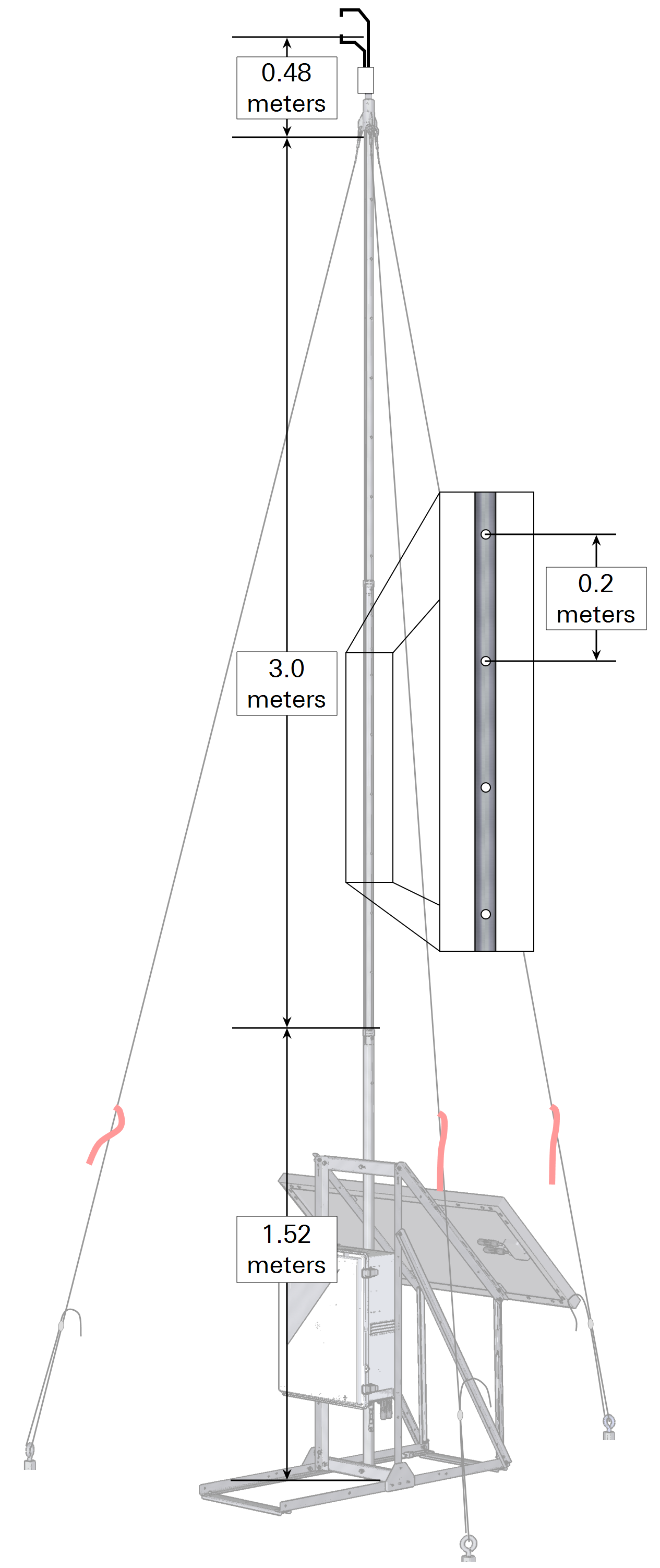
The mast can be adjusted to support the sensor at heights of 2 to 5 meters above the ground. You can estimate the height or measure it directly.