


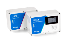
The LI-830 CO2 Analyzer, LI-850 CO2/H2O Analyzer, and LI-870 CO2/H2O Analyzer (LI-8x0 henceforth) are designed to measure gases in a continuous airstream. But in some applications, only a small volume of gas is available for measurement. Because the volume is too small to flow through the LI-8x0 in a normal fashion, small volume injections using a syringe can be used to accurately measure CO2 concentrations. This application note describes a method you can follow to measure small volumes with these gas analyzers.
To measure small sample with the LI-8x0, the air samples are injected into a carrier gas stream flowing continuously through the analyzer, in an open-loop method. The carrier gas is typically free of CO2, provided either from a tank of compressed gas (usually nitrogen) or a chemical scrubber (usually soda lime). If compressed gas is used, no pump is required. For either method, you will need to include a buffer volume to decrease the pressure pulse that occurs at the point of injection.
After the sample is injected, the CO2 concentration through the analyzer will suddenly increase and gradually drop back to its baseline. The height of this peak (or area under the curve) should be compared against peaks with known concentration, to identify the concentration in the air sample. You can use the LI-Integrator software to capture the peak height or calculate the area under the curve. The software is available for download at licor.app.boxenterprise.net/shared/static/1p65n1nhxgqbq19s6ryxiglv3m35vret.
A calibration curve is first generated by injecting standards (different known volumes of known concentrations of CO2) into the carrier gas flowing through the analyzer. A standard curve can be made by plotting the integral of the curve from the calibration samples against the known concentration. For example, if you inject 0.5 mL of 18,000 ppm CO2, you can find the integral of the curve generated from the injection. You can then plot the integral against the known CO2 concentration. Then when you inject your unknown sample, you can plot its integral on the curve to identify its CO2 concentration.
Useful components
The following items may be included with your instrument. Additional components may be purchased from LI-COR.
| Description | Quantity | Part # |
|---|---|---|
| 3-way T-fitting with compression fittings | 1 | 9881-181 |
| Rapid tube fitting nut (LI-830 and LI-850 only; included) | 1 | 9861-036 |
| Quick connect plug (LI-870 only); 1 included in LI-870 spares kit | 1 | 300-07124 |
| AC power supply (LI-870 only) | 1 | 870-772 |
| Silicone septum | 1 or more | 300-08998 |
| Ferrule and nut set | 4 | 300-15025 |
| Bev-A-Line tubing; 1/4" OD; 1/8" ID | 1 (15 m) | 8150-250 |
You should provide following components.
| Description | Quantity | Part # |
|---|---|---|
| Precision syringe; e.g., Hamilton Gastight Instrument Syringe | 1 | - |
| Needle; e.g., Hamilton Metal Needle | 1 | - |
| Acrylic column as buffer volume and/or scrub column | 1 or 2 | 9960-093 |
| Standard gases with known CO2 concentrations | 1 to 5 | - |
Initial setup
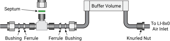
Regardless of whether you use a carrier gas or scrubber to deliver sample through the analyzer, the T-fitting and buffer volume will be assembled in the same way.
-
Connect a short piece of Bev-A-Line tubing to the inlet of the analyzer using the fitting nut (part number 9861-036).
-
Connect a buffer volume to the Bev-A-Line tubing attached to the analyzer.
-
Add ferrules to a section of Bev-A-Line tubing to the T-fitting (9881-181) and attach the Bev-A-Line tube to the buffer volume.
The buffer volume should be between the T-fitting and the inlet of the analyzer.
-
Tighten the nuts onto the T-fitting and gas analyzer.
Tighten by hand until snug and then another ¼ to ½ turn using a wrench.
Preparation: Using a carrier gas
If using a carrier gas, the following items are needed.
| Description | Quantity | Part # |
|---|---|---|
| Flow meter | 1 | 294-03334 |
| Flow meter hose barbs |
2 |
300-03388 |
| Carrier gas with known CO2 concentration | 1 to 5 | - |
| Two-stage regulator (sold with gas tanks) | 1 | - |
| A low-pressure regulator may be needed, depending on the range available from the two-stage regulator. | - | - |
Establishing the standards
A calibration curve is first generated by injecting standards (different known volumes of known concentrations of CO2) into the carrier gas flowing through the analyzer. These would typically be obtained from a tank of known CO2 concentration. There are two options:
-
Connect a Tedlar bag to the tank and fill it with the gas. Close the bag and remove it from the tank and then use a syringe to withdraw a sample from the bag.
-
Connect the 3-way T-fitting with septum directly to the tank. Flow air through the T-fitting at a reasonable flow rate and use a syringe to withdraw a sample from the T-fitting.
Circumventing the internal pump
If your device is not equipped with an internal pump, skip ahead to Connecting the carrier gas. If the LI-830 or LI-850 has an internal pump, or if you are using the LI-870, follow these steps to bypass the internal pump:
-
Remove the top of the gas analyzer (LI-830 or LI-850) or remove the hardware that locks the case and open the lid (LI-870).
-
Identify the tube that connects the optical bench to the pump buffer volume (A in Figure 1); disconnect the quick-connect fitting by pressing the ring in while pulling the tube free.
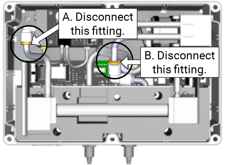
Figure 1. To circumvent the internal pump, start by disconnecting the tubes that connect to the pump. -
Identify the tube that connects the pump outlet to the analyzer outlet (B in Figure 1); disconnect the quick-connect fitting by pressing the ring in while pulling the tube free but leave the elbow fitting connected to the air out tube.
-
Connect the tube that previously connected the optical bench to the pump buffer volume (A) to the elbow connector (B), as shown in Figure 2.
-
Press the tube firmly into the quick-connect fitting.
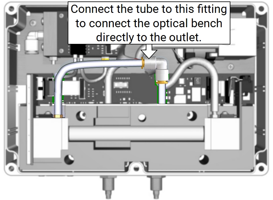
Figure 2. Connect the tube end to the elbow to circumvent the pump. -
Install the gas analyzer top (LI-830 or LI-850) or close the case (LI-870).
Connecting the carrier gas
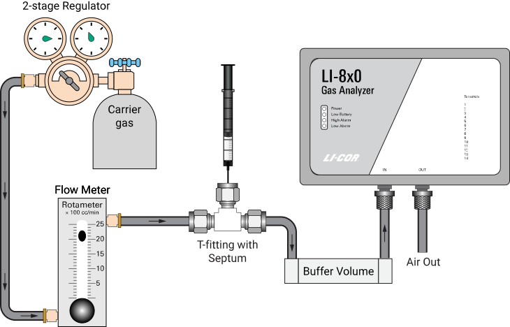
Use a two-stage regulator to achieve a flow rate of 1 liter per minute. A low pressure regulator may be needed.
Preparation: Using a scrub column
If using a scrub column with soda lime, the following items are needed:
| Description | Quantity | Part # |
|---|---|---|
| Acrylic column for soda lime | 1 | 9960-093 |
| Indicating wet soda lime (450 g) | 1 | 9964-090 |
| Gelman filter | 1 | 9967-008 |
| Pump, required only if your LI-830 or LI-850 does not include the internal pump (the LI-870 always has an internal pump) | 1 | 800-910 |
Attaching the scrub column
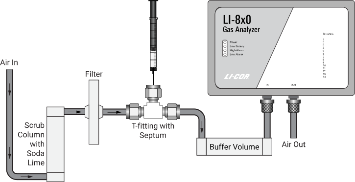
In this scenario, the built-in pump will draw air through the gas analyzer. If your analyzer is not equipped with the built-in pump, an external pump will work fine.
Configure the gas analyzer
Before using the LI-Integrator app, you'll need to configure the gas analyzer output rate and disable the internal pump controls. Here's how:
Configure the output rate
-
Power on the analyzer.
-
If using an LI-870, use the 870-772 AC power supply.
-
If using an LI-830 or LI-850, use the 591-19495 universal power adapter or provide 12 to 30 VDC to the power connectors on the terminal strip.
-
-
Connect the analyzer to a computer with a USB or serial cable (RS-232).
-
Connect to the instrument using the Windows or Mac interface software
If you don't have it yet, download the software from licor.com/env/support/LI-850/software.html and install it on your computer.
-
When connecting, set the Data rate to 1.0 seconds and click Connect.
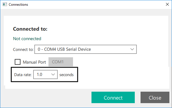
This will set the output rate of the analyzer to 1 Hz, which is required for the LI-Integrator software. (The default output rate is 0.5 Hz.)
Configure the pump setting and allow the analyzer to warm up
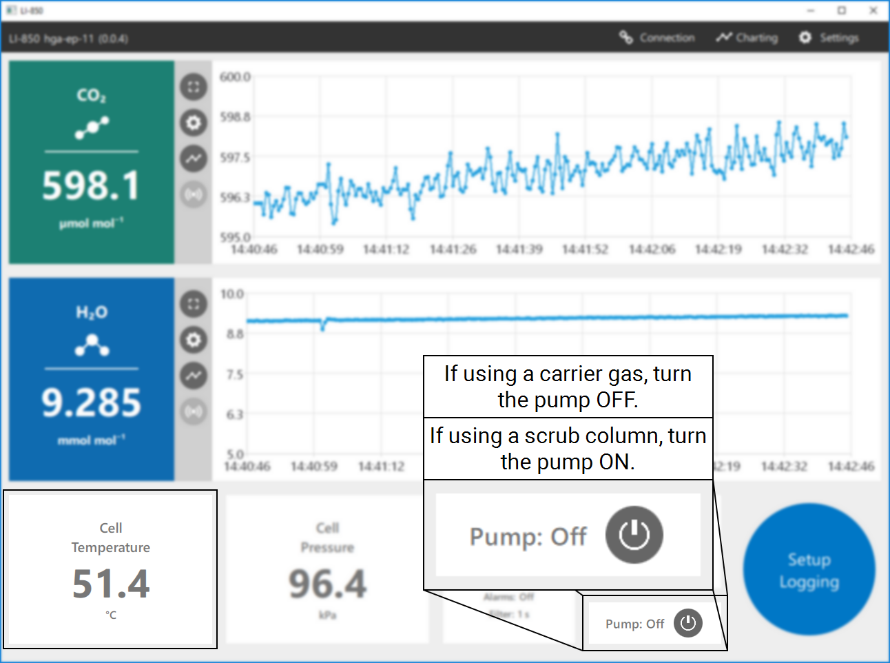
The pump setting is at the bottom right corner of the main page.
-
If using a carrier gas, turn the pump off.
-
If using a scrub column, turn the pump on.
Be sure the cell temperature has reached 51 °C, indicating that it is ready for measurements.
Taking measurements
Now you're ready to configure the integration calculations and measure the samples.
Prepare the LI-Integrator app
-
Open the LI-Integrator software and connect to the instrument.
The LI-Integrator app is available for 64-bit Windows PC at licor.app.boxenterprise.net/shared/static/1p65n1nhxgqbq19s6ryxiglv3m35vret
-
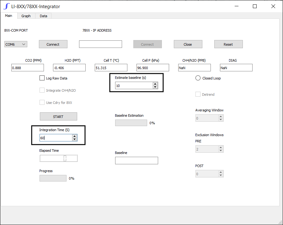
Set the desired time to Estimate Baseline and Integration Time, both in seconds.
These can be adjusted later if you see that the settings are not adequate.
-
In the LI-Integrator app, be sure the gas analyzer cell temperature has reached 51 °C, indicating that the analyzer is ready for measurements.
-
Allow the carrier gas to flow through the instrument cell at a rate of about 1 liter per minute.
-
Allow the instrument to stabilize at the concentration of gas you are flowing through the instrument.
Measure the sample
You'll be collecting the sample in a syringe.
-
Draw the sample air into a syringe.
Collect a volume that is slightly larger than the volume you want to measure. Immediately before you inject the sample, expel some air from the syringe leaving the desired volume.
-
Insert the needle through the septum.
Wait a second or two for any pressure perturbations to pass through.
-
Click the Start button in the LI-Integrator software and wait for the baseline to be established.
-
Inject the sample at a steady rate.
You should see an increase in the CO2 concentration.
-
Wait for the CO2 concentration to return to the baseline.
If using soda lime, the baseline may change throughout the day as the soda lime dries out or becomes exhausted.
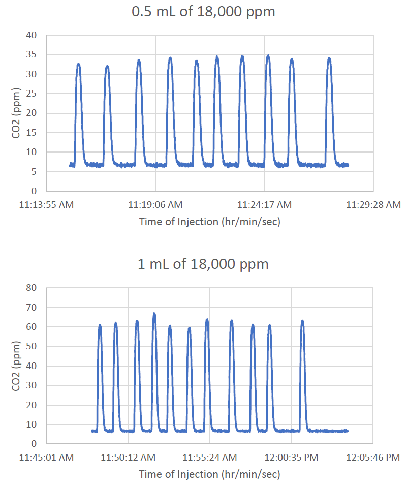
Repeat the steps in Measure the sample as many times as needed. We recommend doing 5 to 10 injections of known volumes of a known concentration of CO2 gas to create the calibration curve. If you only have one calibration gas, you can vary the volumes to create different points on the calibration curve. You can perform the same number of injections of your unknown sample, or fewer if you have a limited supply.
Data analysis
-
Plot the data in a spreadsheet application.
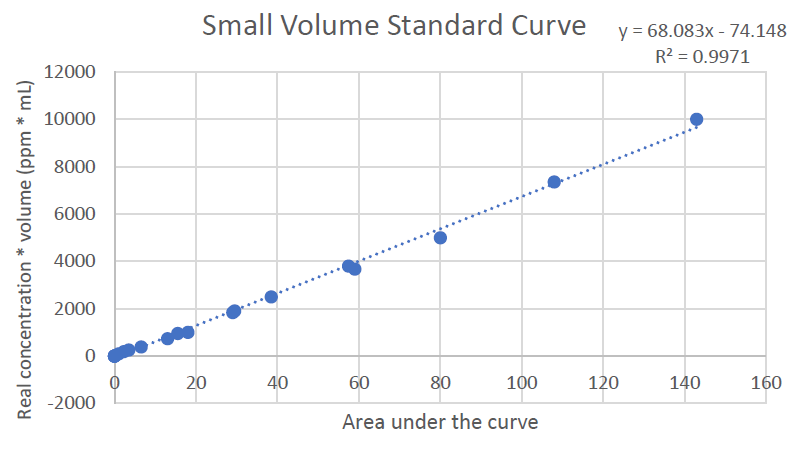
The x-axis should be the area under the curve. The y-axis should be the known CO2 concentration of the standard, multiplied by the volume injected.
-
Fit a line through the points and calculate the slope and offset (y = mx + b).
This is the calibration curve.
-
For each unknown sample, insert the area as x into the equation.
-
Solve for y, then divide by the volume of the sample.
This will give you the CO2 concentration in the sample.