Using the gas analyzer
This section describes how to power on and connect to the instrument.
Powering on the instrument
The analyzer should measure ambient air during power on and initialization. Allow about one hour to complete initialization.
Caution: Remove the protective caps from the air inlet and outlet before powering on the instrument. The instrument will fail to initialize if the caps are in place. Use the caps when storing or shipping the instrument.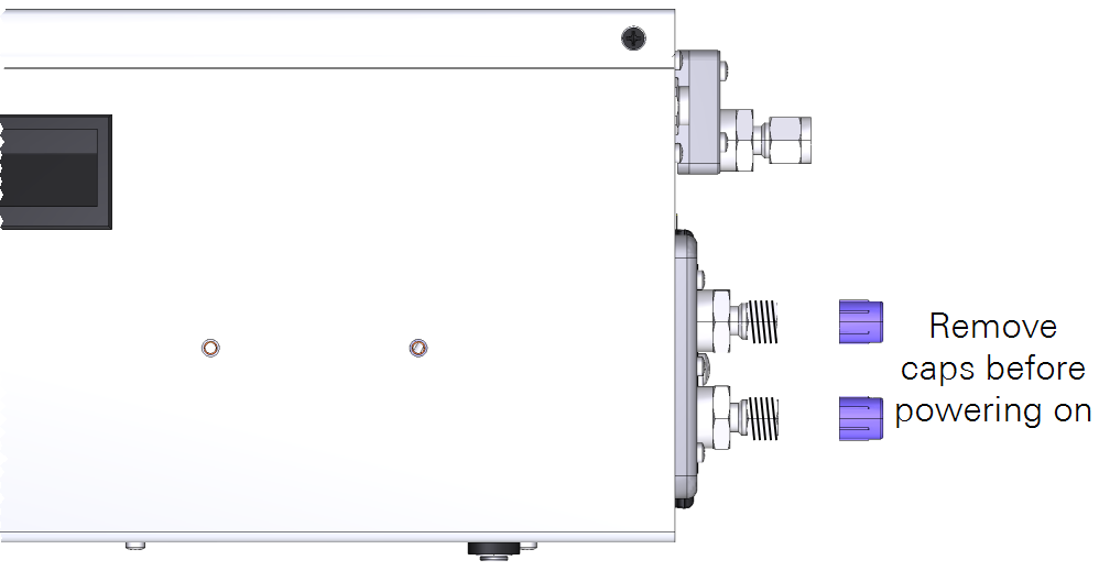
To power on the instrument, either install a battery and push the power button or connect the instrument to an external power supply. The instrument will power on any time power is supplied through the AC power adapter or the auxiliary power cable.
If main power is lost, the instrument will run until the batteries are depleted and then it will power off. When the main power is restored, the instrument will power up and the batteries will resume charging. When powered by batteries only, you must press the power button to turn on the instrument.
Upon powering on, the instrument will issue a series of status codes as it completes the start up cycle. The pump will start running when the optical bench approaches 55 °C. If starting from room temperature, it will take about 20 minutes before you can connect and another 10 or 15 minutes before it provides accurate measurements. If the instrument is very cold, it will take longer to warm up.
The instrument cannot be powered on from afar. You can restart the instrument through the software interface, but if you power it off through the software interface or the power button, you must press the button or reconnect the main power supply to turn it back on. See Powering off the instrument for additional details.
Connecting with the instrument
Connect with the instrument using a web browser on a computer, tablet, or smart phone that is on the same network as the instrument.
-
Connect a network cable between the instrument and a computer or local network.
When connected to a network, the instrument will display the network icon (
 ) and the assigned IP address. If the local network has Wi-Fi, you can connect to the instrument over the wireless network.
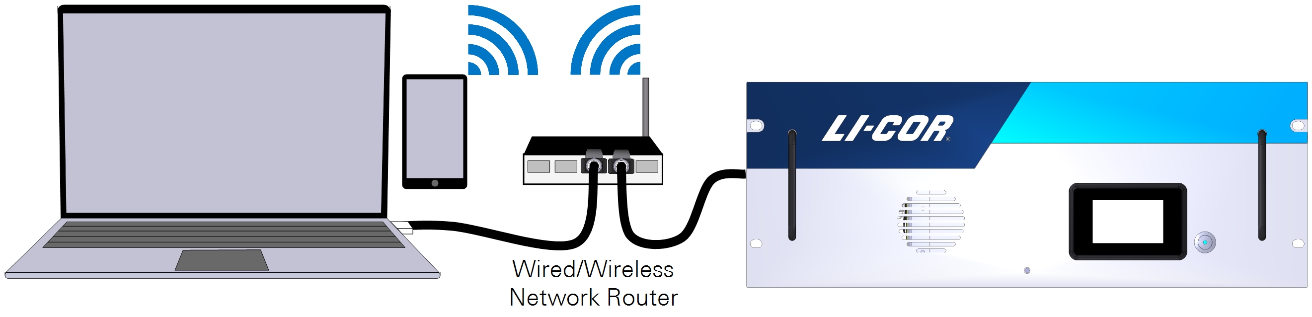
-
Enter the hostname or IP address in a web browser address bar.
Both the hostname (which is the instrument serial number) and IP address are given on the display. Type one or the other into the address bar:
- Hostname: Enter http://atg15-nnnnn.local where atg15-nnnnn is the hostname (and the serial number) of your instrument.
- IP address: The IP address on the display panel.
-
Press Enter to connect.
The interface will load into the browser window.
Unable to connect? See Connection problems for troubleshooting.
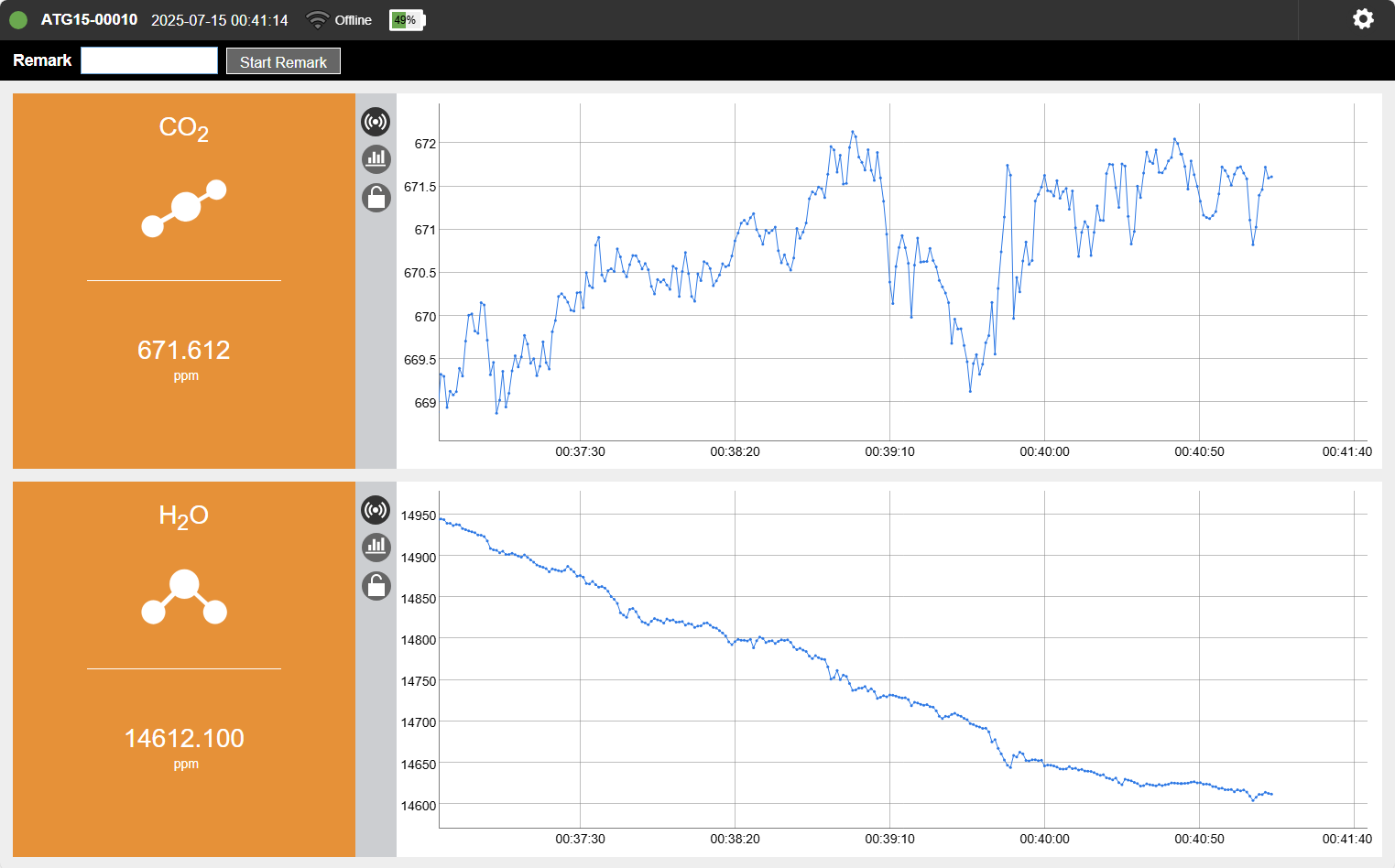
Instrument display
The instrument display panel provides useful information at a glance.
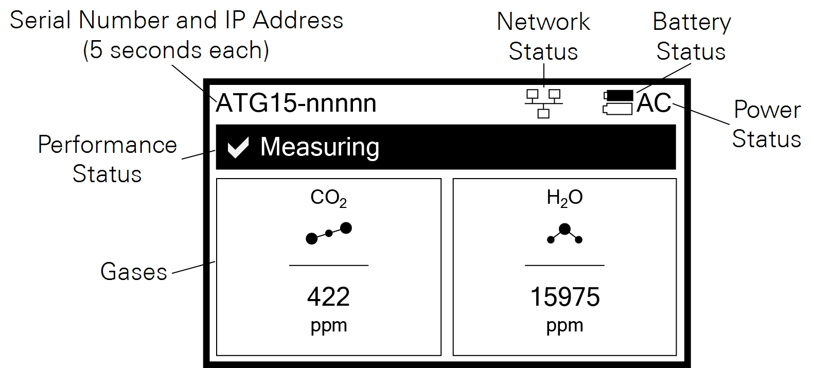
- Serial Number and IP Address: The instrument serial number (hostname) and network-assigned IP address (IPv4) rotate for 5 seconds each. The serial number is also printed on the case label.
- Network Status: When visible (), the instrument is connected to a network.
- Battery Status: Indicates the charge status (
 ). A solid black battery indicates a full charge; an outline indicates a discharged battery. The battery icon is not displayed when no batteries are installed.
 - Power Status: Indicates the power source (AC if power cable connected).
- Performance Status: Indicates performance status of the instrument.
- Gases: The gases measured and their concentrations.
Status codes
Status codes are given on the instrument display panel, software interface, and recorded in the data set, where they are associated with measurements.
 Green
Green
 Yellow
 Red
RedStatus codes are additive: if multiple codes are active, the displayed value is the sum of the codes. For example, a display code of 23 indicates that the instrument is initializing the start-up mode (16), it has an incomplete scan (4), laser temperature adjustment is underway (2), and a start frequency adjustment is underway (1). Non-zero status codes are displayed during warmup and any time the instrument is not in a normal state. Typically, status codes will be resolved by the instrument. Occasionally, you may need to restart the instrument to resolve the code. If a code is not dismissed for several hours or after restarting, contact technical support.
Configuration options
The instrument supports two operating configurations that can be set in the interface: Standard and High Altitude.
Standard
The standard configuration is the default - it will be loaded automatically unless the configuration has been changed under Options > Settings > Software > Configuration.
High altitude
The high altitude configuration does not require any hardware modifications. The reduced flow rate hardware modifications cannot be used while the instrument is in the high altitude configuration; if the kit has been installed, remove it before using the high altitude configuration. To use the high altitude configuration, select it under Options > Settings > Software > Configuration and restart the instrument. Be aware of slight differences in the performance specifications of the instrument while in the high altitude configuration.
See Specifications for details.
Reduced flow rate kit
The reduced flow rate kit (part number 7800-113) enables the analyzer to operate at a nominal flow rate near 70 sccm, rather than the standard nominal flow rate near 250 sccm. One kits is required to use the Reduced Flow Rate configuration. To install the kit:
- Power off the instrument.
- Remove the nine screws that secure the top, and then remove the top.
-
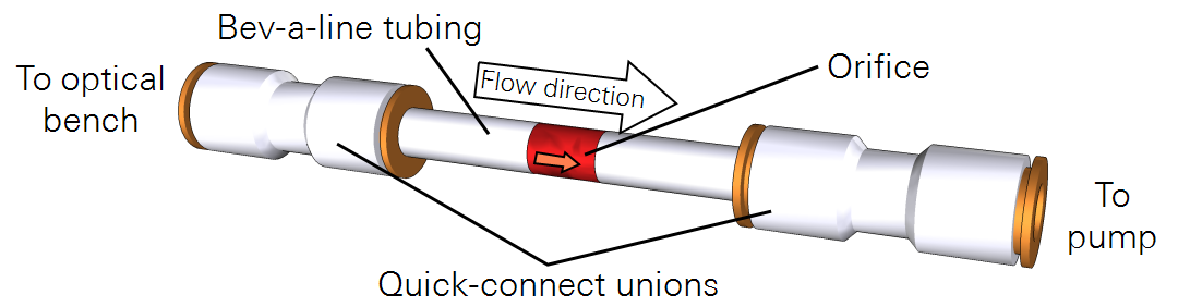
Identify the tube that connects the pump manifold to the optical bench.
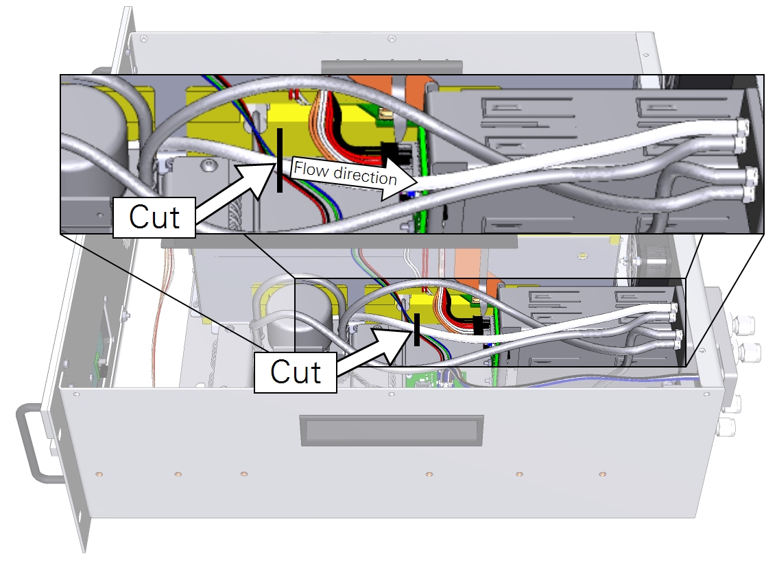
- Cut the tube where indicated.
- Observe the flow direction indicator on the assembly and install it between the two cut ends with the arrow pointing from the optical bench to the pump.
- For each quick connect, insert the tube and push firmly until it stops.
-
Restart the instrument.
The instrument will start up and operate with a flow rate of approximately 70 sccm.
To restore the normal flow rate, remove the reduced flow rate kit, connect the cut tubes with a quick-connect, and restart.
Powering off the instrument
The instrument can be powered off with the power button or through the software interface. To Power Off the instrument with the button, press it three times within 5 seconds. To enter Sleep Mode, press the power button twice within 3 seconds. In sleep mode, the instrument will power off the pump but maintain power to the heaters. To Exit Sleep Mode, press the power button after waiting at least 5 seconds after the previous press.
Caution: While in sleep mode, the instrument will stop drawing in air, which may affect the pressure and flow in your air supply system. Do not enter sleep mode when the air inlet or outlet is subject to positive or negative pressure. Pressures exceeding 110 kPa absolute pressure may damage the instrument.
If a battery becomes depleted during normal operation, the instrument will complete the dry-down cycle before shutting itself down. If the instrument is inadvertently powered off and prevented from completing the dry-down cycle (by removing the batteries and power cable, for example), power it back on and off again so it can complete the dry-down cycle.
Caution: Failure to complete the dry-down while powering off the instrument may result in condensation in the optics, which will damage the instrument.
