Introduction to the data acquisition system
In a typical application, the data acquisition system will sample each analog signal once every second and SDI-12 sensors once per minute. Readings from each sensor are averaged over one minute and the average is logged. These data are then combined with high-speed eddy covariance data for processing in EddyPro Software on a desktop computer or the SmartFlux 2 or 3 System (SmartFlux System henceforth), and subsequent analysis in Tovi Software.
What's what
If you have just taken delivery of the order, double check the shipment to be sure everything is included.
Blueprint Utility software

Blueprint Utility software is a graphical application that is used to program the data acquisition system. Go to licor.com/support/Biomet-System/software.html for the latest download.
Data Acquisition Module
Part number: 7900-110
At least one Data Acquisition Module (DAqM) is required in the data acquisition system. It sends a stream of time-stamped data to the SmartFlux System, another DAqM, or a DRM. Up to four DAqMs can be connected together.
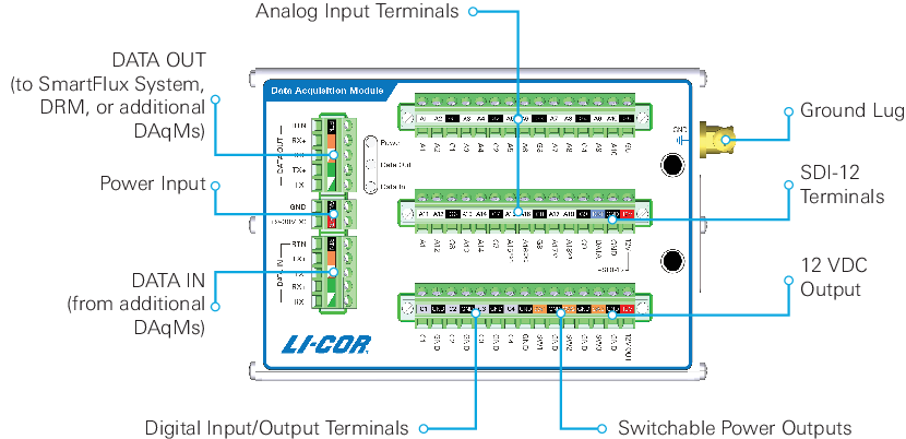
- Analog input terminals: Connections for analog sensors (terminals A1 to A18). Terminals A15 and A16 can provide excitation voltage as well. Terminals A17 and A18 can read voltage or current. Analog voltage and current ranges are software-settable.
- Ground lug: Connect to earth ground for lightning protection.
- SDI-12 terminals: Connections for SDI-12 sensors. Terminal blocks are used to connect multiple sensors. Each DAqM supports up to 10 SDI-12 sensors.
- 12 VDC output: Regulated power supply.
- Switchable power outputs: Controlled power for sensors (SW1, SW2, and SW3).
- Digital input/output terminals: Connects digital sensors.
- DATA IN: Receives data from an additional DAqM. Sends configuration to connected DAqMs.
- Power input: Power to the DAqM.
- DATA OUT: Sends data to SmartFlux System, DRM, or another DAqM. Receives configuration from SmartFlux System, DRM, or another DAqM.
- Indicator LEDs: Shows power, send, and receive status.
- Power: Green = OK; Red = Fault on switchable power outputs (see DRM or DAqM LED indicators for details).
- Data Out: Green = Sending data; Red = Receiving data.
- Data In: Green = Sending data; Red = Receiving data.
Data Acquisition Module wire leads
Part Number: 9579-005
Each DAqM includes wire bundles for RS-485 data, SDI-12 terminals, and power.
Data wires
A 23-cm and a 46-cm bundle of five wires connect RS-485 DATA IN/OUT ports on the DAqM, DRM, or SmartFlux System. Only one bundle is required to connect the devices: use the short one if the components are close together; use the long one if they are far apart. One will remain unused. See Figure 2‑5 and for details.
Power and ground wires
A 30-cm and a 46-cm bundle of red and black wires connect the power supply. Only one is required. Choose the ideal length for the setup. A single insulated solid core green/yellow wire is to connect the ground lug to the ground terminal in the enclosure. See Initial assembly for details.
SDI-12 wires
One red, one black, and one blue wire lead (18-cm) connect the SDI-12 terminals on the DAqM to the DIN terminals in the enclosure. See Initial assembly for details.
Data Retention Module
Part number: 7900-115
The optional Data Retention Module (DRM) provides four regulated power outputs (12 VDC maximum), a charge controller for the backup battery, and temporary data storage for biomet sensors attached to DAqMs. In the event of a mains power outage, the DRM can continue to operate on backup battery power and store biomet data from the DAqMs, which it sends to the SmartFlux System when its memory is full or when main power is restored.
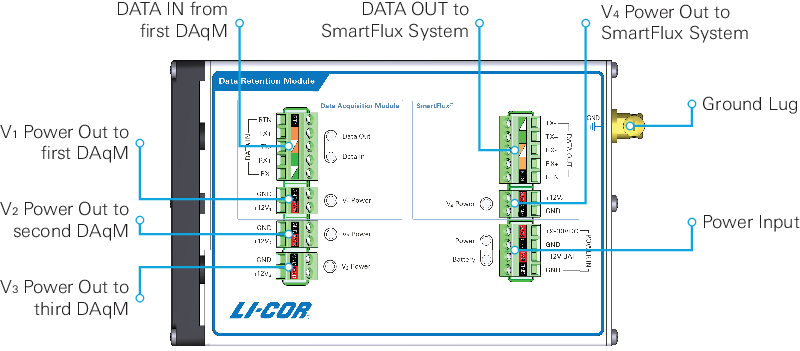
- DATA IN: Receives data from a DAqM. Sends configuration to DAqMs.
- DATA OUT: Sends data to SmartFlux System. Receives configuration from SmartFlux System.
- Ground lug: To ground the electronics. Connect to earth ground.
- Power input: Power in to the DRM. The +9 - 30 VDC and upper GND terminal are the primary power supply. The +12V BAT and lower GND terminal are for a backup battery.
- V1, V2, and V3 Power: Regulated power output (12 VDC maximum) to DAqMs, power terminals, or accessories.
- V4 Power out: Power out for the SmartFlux System.
- Indicator LEDs: Colors and blink patterns indicate the following:
- Data Out: Green = Sending data; Red = Receiving data.
- Data In: Green = Sending data; Red = Receiving data.
- V1, V2, V3, and V4 Power: Green = Power OK; Red = Error.
- Power: Green = OK; Red = Powered from backup battery.
- Battery: Green = Powered by main power, battery connected and fully charged; or powered by backup battery; Yellow = Powered by main power, battery connected and charging. Red = Battery not connected (normal) or error if battery is connected.
Data Retention Module wire leads
DRM wire bundles are for data and power.
Data wires
Part Number: 9579-007
Each DRM includes a bundle of five data wires (15 cm) that are used to connect the DRM to the SmartFlux System. See Figure 2‑5 and for details.
Power and ground wires
It also includes two sets of power wire bundles: a 30-cm and a 46-cm bundle. Only one is required. Choose the ideal length for the setup. A single insulated solid core green/yellow wire is to connect the ground lug to the ground terminal in the enclosure. See Initial assembly for details.
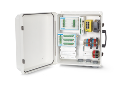
Pre-configured biomet system enclosure
Part Number: 7900-126
The pre-configured enclosure is a large weather resistant box with mounting hardware. It is set up for the LI-COR Biomet Data Acquisition System and other accessories. It includes all of the terminal connections and DIN rails required for a complete eddy covariance system.
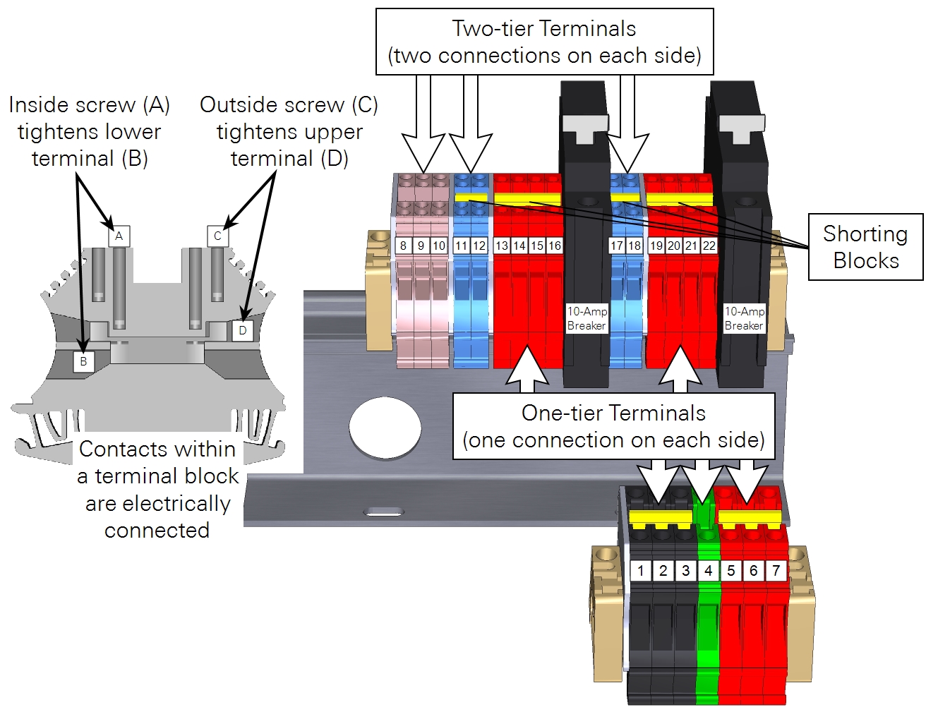
Enclosure terminal connections
The enclosure provides 22 DIN terminals to connect wire leads and two 10-amp breakers to protect devices from a surge. Terminal assignments are described in Table 1‑2.
Enclosure wire leads
Part Number: 9579-006
The enclosure includes several wires that are used to connect power supply terminals inside the enclosure. It includes two black wires, four red wires, and one solid core green/yellow wire for grounding. See Initial assembly for details.
Enclosure accessories kit
Part number: 9979-063
The accessories kit includes a number of spare components. Some items listed below may be installed in the enclosure prior to delivery.
Mounting Kit
Part Number: 9979-021
The 33-cm mounting kit includes brackets, band clamps, and hardware that is used to mount the enclosure to a tripod or tower.
Strain relief fittings
Part Number: 6579-040
Three 1.5-inch drilled PVC couplers are to relieve strain from the wire leads. Sensor wires should be secured to the strain relief fittings using cable ties so that the connections are not bearing the weight of the cables. Includes three couplers and three lock nuts (part number 259-12760).
Coarse wool three-pack
Part Number: 9979-032
Coarse metallic wool is to cover any opening that accommodates cables. The metallic wool will help keep insects and other animals from inhabiting the enclosure and may prevent water from splashing into the openings.
Screwdriver
Part Number: 611-12864
A 3-mm slotted screwdriver can be used to connect wire leads to terminals.
Nylon cable ties
UV-resistant cable ties are used to secure cables in the strain relief fittings and to secure cables to a tripod or tower. Ten each of 29-cm cable ties (part number 218-11027) and 10.5 cm cable ties (part number 218-08499) are included.
Cap plugs
Three large and one small red cap plugs (part numbers 620-12831 and 620-16842, respectively) are to cover any unused openings in the enclosure.
Biomet sensor packages
The data acquisition system probably comes with one of three sensor packages. Complete installation and configuration instructions for biomet sensor packages are provided in this document.
Basic sensor package
Part number 7900-109
This collection of sensors includes the items listed in Table 1‑3. Cables for the net radiometer, LI-190R, LI-200R, and HMP155, are suitable fro most tripods. Longer cables are available (specified while ordering) to accommodate tripods, short towers, and tall towers.
Standard sensor package
Part number 7900-118
This collection of sensors includes the items listed in Table 1‑4. Cables for the net radiometer, LI-190R, and HMP155, are available in a variety of lengths (specified while ordering) to accommodate tripods, short towers, and tall towers.
Premium sensor package
Note: The StarDot NetCam SC (PhenoCam) has been replaced by a new model - the NetCamLIVE2. The NetCamLIVE2 is a direct replacement and is supported by SmartFlux 2 and 3 Systems (firmware v2.4.2 and newer).
Part number 7900-119
This collection of sensors includes the items listed in Table 1‑5. Cables for the net radiometer, LI-190R, and HMP155 are available in a variety of lengths (specified while ordering) to accommodate tripods, short towers, and tall towers.
Optional items
Additional components may be required for tower installations or other scenarios. These may be included with the order, or they can be ordered separately.
TDK-Lambda DC-DC converter
Part Number: 591-15617
The TDK-Lambda DC-DC Converter (model DPX60) is required if these conditions are met: 1) the EC system has a 24 VDC solar power supply, 2) it includes components that have an upper voltage limit that is <24 VDC, and 3) it does not have regulated power outputs from a DRM. You may use this to power the PhenoCam, Hughes Satellite Gateway, or the SmartFlux System with an attached CSAT3 sonic anemometer.
Backup battery
Part Number: 7900-129
The backup battery (12 VDC, 7.2 amp hour) will deliver backup power to the data acquisition system via the DRM if the main power supply drops out. This makes it possible for some components of the system to continue measuring parameters and recording data even if the other instruments are powered off. The backup battery is charged by the DRM. The battery is a nonspillable lead acid battery.
Note: Do not store the battery in a discharged state. Doing so may damage the battery. Do not charge the battery in a gas-tight container. The biomet enclosure is vented adequately for the battery. Do not short the terminals. If you are exposed to the electrolyte, flush with water.
Power cable
Part Number: 392-14582
A 5-meter long 2-conductor wire with bare leads on both ends.
DIN rail
Part Number: 6579-023
Extra pieces of DIN rail (18.6 cm) are available if the included rails are insufficient to mount components in the enclosure.