The simplest way to create a custom program is to modify one of the preinstalled datalogger configurations by removing or adding sensor blocks. Alternatively, you can create custom programs that support a custom set of sensors. The latter is described below.
The configuration described here will result in logged data files that can be embedded into .ghg files (logged to the LI-7550) and processed by EddyPro, where they will be summarized with EddyPro output and may be used to improve the results of flux computations. If the datalogger is configured properly, the data will also be stored in the datalogger's internal memory. It can be retrieved and processed in EddyPro as external biomet data or viewed in a spreadsheet such as Microsoft® Excel®.
Before getting started, there a few things you should know that will help get the system working properly—and hopefully avoid the headache that results when you realize the system was logging nonsense because a bad configuration.
There are two aspects to creating a custom program: Initial Setup and Adding Sensors.
- Initial Setup: LogRec and Measure blocks specify global criteria that the datalogger uses to determine 1) which sensors need to be included in the logged data record, 2) which directory the datalogger should use to store the data, and 3) how often to record the output of each sensor (see Initial Setup).
- Adding Sensors: Here you specify 1) which sensors are providing data, 2) how the datalogger should process data from the sensor, 3) how to provide the data to external storage such as the LI-7550, and 4) supplementary information about the logged variable.
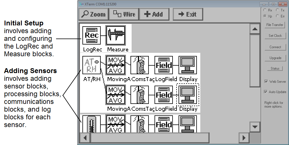
Note: To enter the graphical window shown above, select Graphical Setup, then click View.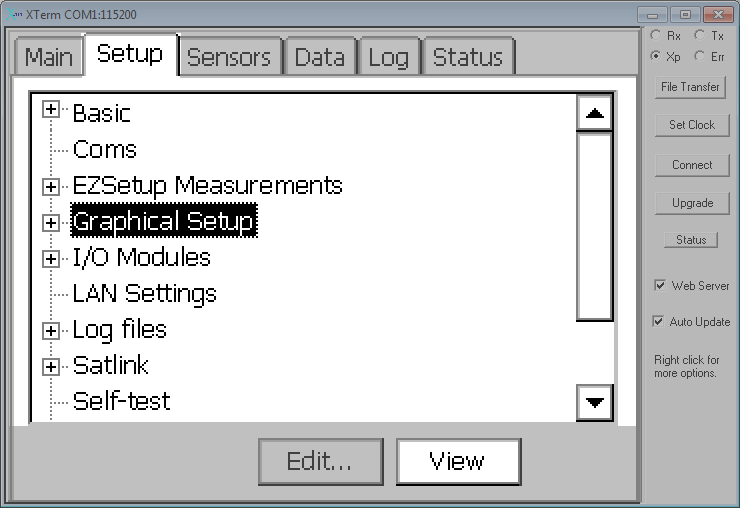
Initial Setup
The steps below describe the initial setup and configuration of the LogRec and Measure blocks. This is required for any custom program.
- Create a New Program.
- Connect to the datalogger (see Configuring the Biomet System).
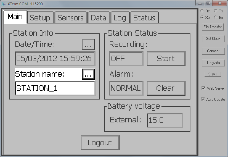
- Create a new Station name.
- Important: The Station name and Setup File name must be the same. When the datalogger powers up it will automatically load the setup file with the same name as the station. If the names do not match the datalogger will not load a setup file when it restarts, resulting in a failure to record data.
- Click on the Setup tab, select Setup File and then New.
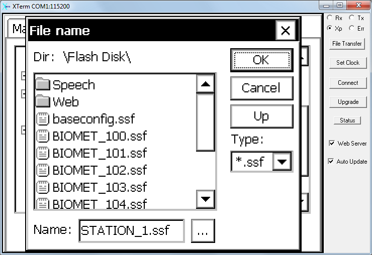
- Give the setup file the Station Name that you provided earlier and click OK.
- Configure Datalogger Channels.
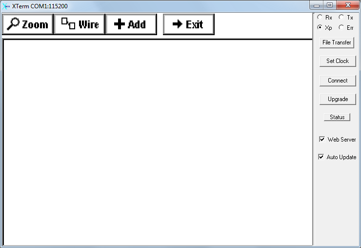
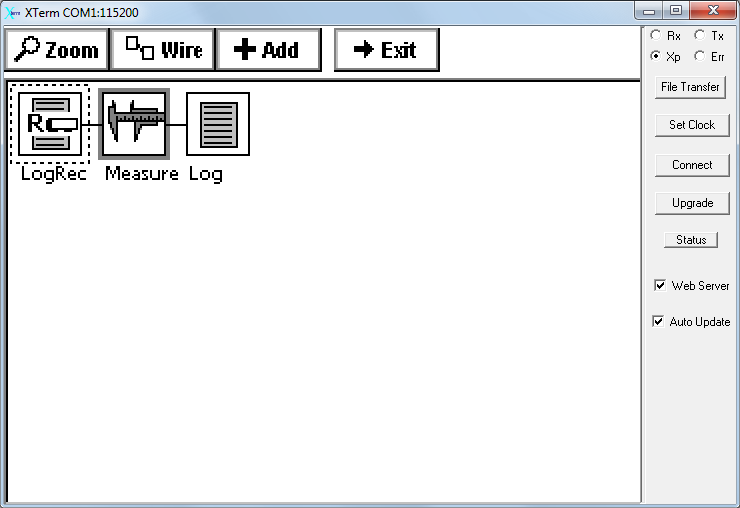
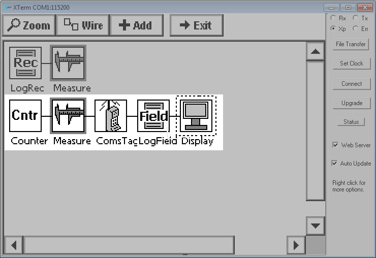
- Channels are configured in the Graphical Setup tab. Click Graphical Setup and then click the Edit button. The blank screen awaits your configuration instructions:
- The following steps describe how to configure a variety of commonly-used sensors. Configurations that support other sensors, as well as additional information about the Sutron 9210B, are in the Sutron Datalogger instruction manual.
- Add the LogRec and Measure Blocks.
- The LogRec and Measure blocks specify how the datalogger will record the data.
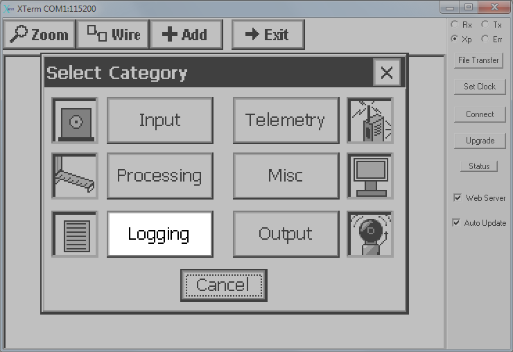
- Click the Add button and then click Logging.
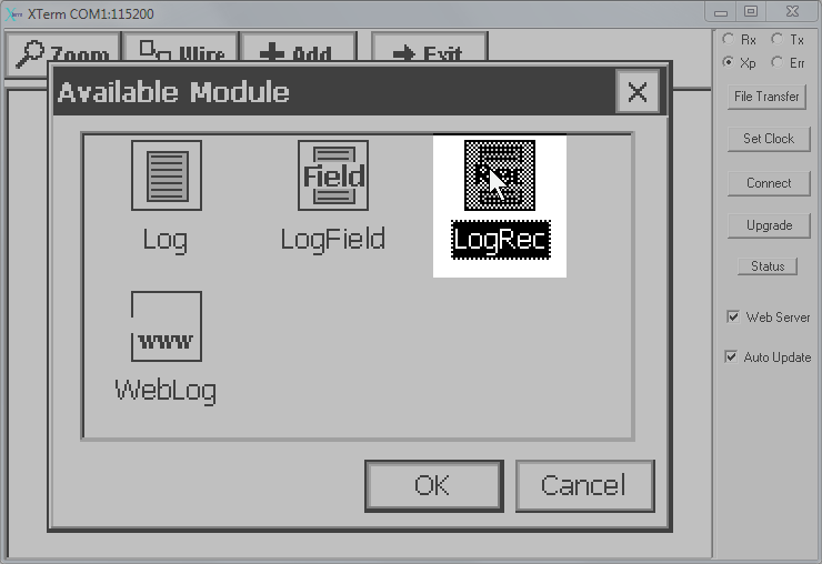
- Click LogRec and then OK.
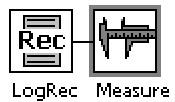
- The software will automatically add the LogRec and Measure blocks, and an unnecessary Log block:
- Delete the Log block—click on it and select Delete so that only the LogRec and Measure blocks remain as shown:
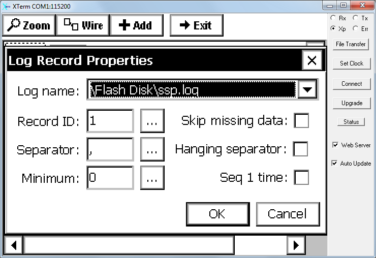
- Click the LogRec block and select Edit Properties. Configure it as described below:
-
- Log name: The name of the file where the logged data will be stored. If you added an SD card or USB drive, select that drive and file for the log name (see Adding Memory).
- Record ID: Identifier used by the datalogger. The value entered here must correspond with a RecordID for each sensor. Leave it at the default setting or enter a number or string. See Adding Sensors for details on the RecordID.
- Separator: Field separator character that will be used if you view data as it is logged.
- Configure the other settings as shown above.
- Click OK to confirm the configuration.
- Then edit properties of the Measure block. Configure it as shown:
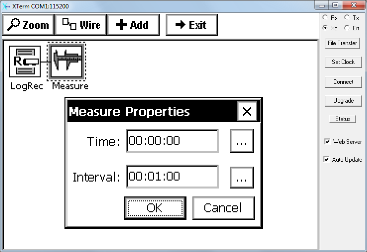
The Time setting is an offset that specifies how much time should pass between when the variable is measured and logged. The Interval is set to 00:01:00, indicating that a record will be recorded every 1 minute.
IMPORTANT: Save the program or your changes will be lost! To save, exit the Graphical Setup window and click the Main tab or any other tab.
This section provides a quick overview of how to add sensors to a program. There are four aspects to this:
- Specify which sensors are providing data,
- Specify how the datalogger will process data from the sensor,
- Specify how to the datalogger will provide the data to external storage such as the LI-7550 for inclusion in .ghg files,
- Provide information about the logged variable.
Overview of Supported Sensors
The 9210B datalogger supports numerous sensors with default sensor "blocks" in Graphical Setup mode. Some commonly used blocks are given below:
- Stevens Hydra Probe II: See Soil Probe—Stevens Hydra Probe II.
- 7900-180 Soil Temperature Probe: See Soil Temperature Probe (LI-COR 7900-180).
- LI-190R, LI-200R: See PAR Sensor (LI-190R or LI-190SL).
- NR Lite2, CNR4: See Net Radiometer (NR Lite2 or CNR4).
- HMP155: See Humidity and Temperature Probe (HMP155).
- HFP01: See Soil Heat Flux Plates (Hukseflux HFP01)
- HFP01SC: See Self-calibrating Soil Heat Flux Plates (Hukseflux HFP01SC).
- Tipping Bucket Rain Gauge: See Rain Gauge (Texas Electronics TR-525M).
- Other Sensors: If the datalogger lacks a block for a sensor, use the ADC block for voltage output or another appropriate block.
Additional sensors, other than those listed here, are supported by the Sutron 9210B. To learn about these sensors, refer to the Sutron 9210B Datalogger Instruction Manual.
These steps show how to add a sensor using the ADC (analog-to-digital) block. However, many sensors are supported by pre-programmed blocks, which are configured similarly simply by selecting a sensor block rather than the ADC block. For a partial list of supported sensors, see Overview of Supported Sensors.
- Add an ADC Block.
- For new configurations or to add a sensor to an existing configuration, load the configuration file and enter Graphical Setup (click Graphical Setup > Edit).
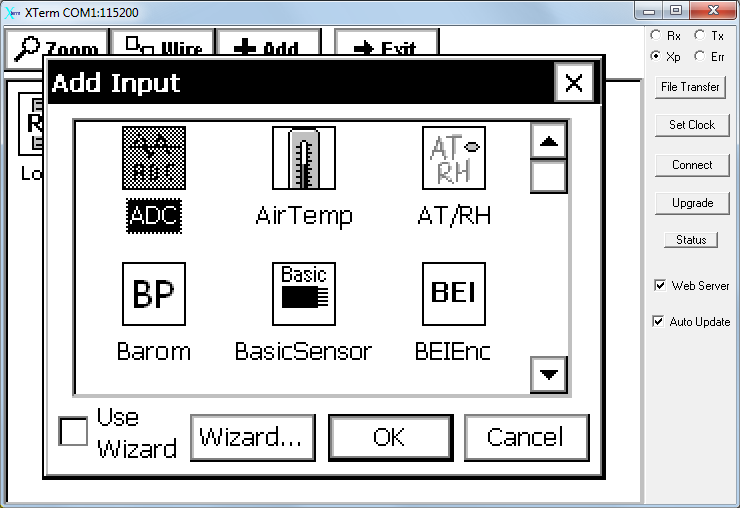
- Click the Add button, then click Input.
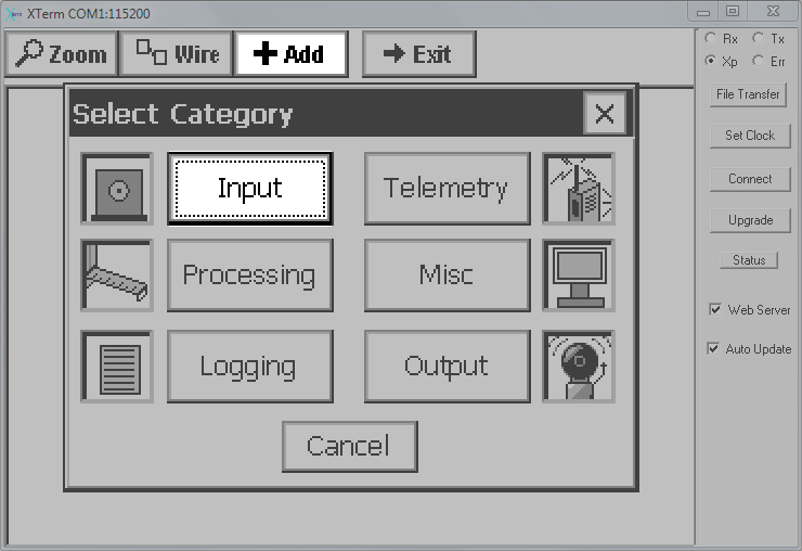
- In the resulting dialog select the Input block and click OK. In this example we chose an ADC block. Uncheck the Use Wizard box if it is checked.
- The software will return to the graphical setup display, now showing the ADC block.
- Rename the block however you want for good record keeping. Click on the block and select Rename from the menu.
- Configure the ADC Block.
- Click on the ADC block and select Edit Properties.
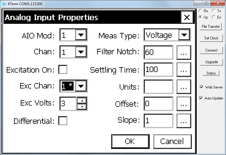
- Configure the following:
-
- AIO Mod: Select the Analog I/O Module. The terminal strip on the datalogger is designated as AIO1. Other modules are numbered according to your assignment (see Add AIO Modules).
- Chan: Select the channel on the AIO module that will record the data. Channels are labeled CH1, CH2, etc. on the terminal strips. For differential measurements, always connect the positive signal to an odd numbered channel (e.g., CH1, CH3) and the negative signal to the next higher channel in the series.
- Excitation On: Turn excitation voltage on or off.
- Exc Chan: The excitation channel that allows the datalogger to read an excitation voltage.
- Exc Volts: The excitation voltage.
- Differential: Check this box if the measurement is differential. Leave it unchecked if the measurement is single-ended.
- Meas Type: Select the output type provided by the sensor.
- Filter Notch: Built in noise filter. The default value of 60 is suitable for most measurements.
- Settling Time: The amount of time to leave the ADC circuitry powered before recording a measurement. Also called warm-up time.
- Units: This is one of several places where the units can be specified. Enter the units here or in the LogField block (preferred), which is described later.
- Offset: b of y=mx+b.
- Slope: m of y=mx+b.
- Add the MovingAverage Block.
- The MovingAverage block instructs the datalogger to compute the average at a specific interval for data recorded over the preceding time period.
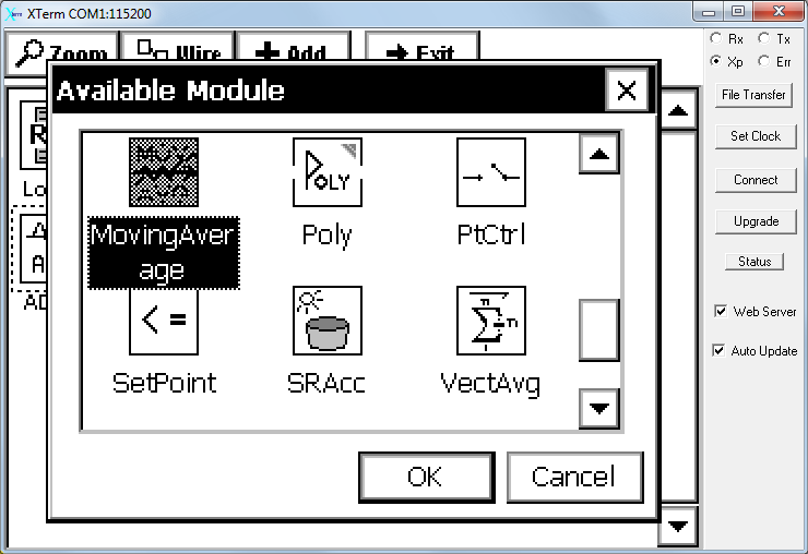
- Click the Add button, then click Processing. Select MovingAverage and then click OK.
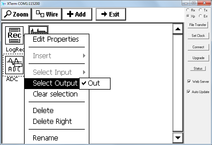
- Note: The software may give an error message suggesting that you have not "Selected an output." To solve this, click on the Input block and Select Output. Choose the output that corresponds with the channel you are configuring.
- Configure the MovingAverage Block.
- To configure these settings, click the moving average block and then click Edit Properties.
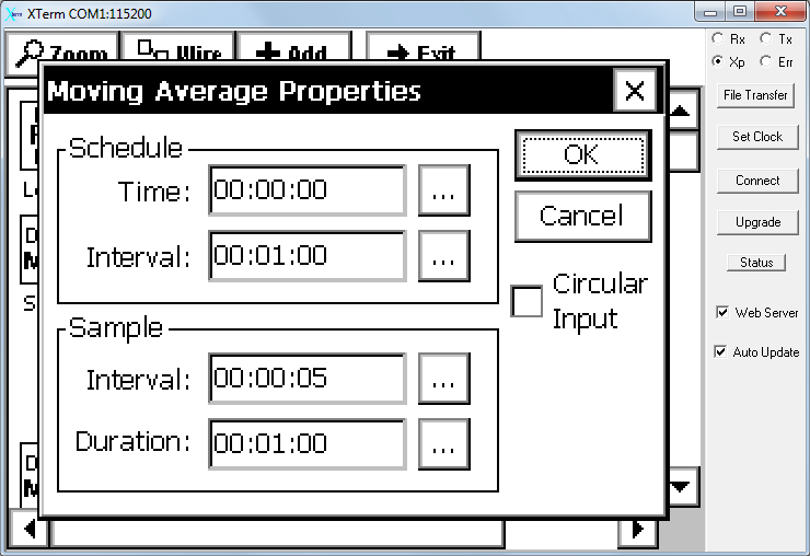
- Configure the settings:
- Schedule: Controls when the software initializes the computation.
-
- Time: An offset that specifies the time at which averaging starts.
- Interval: The time at which the averaging starts (or how often the averaging starts).
- Sample: Controls the averaging period and interval.
-
- Interval: Time between samples.
- Duration: Duration of the averaging period.
- In the example above, the datalogger will measure the output from the sensor every 5 seconds (Sample Interval) and use that to compute a 1 minute average (Sample Duration). The average value will be logged every 1 minute (Schedule Interval), on the minute (Schedule Time).
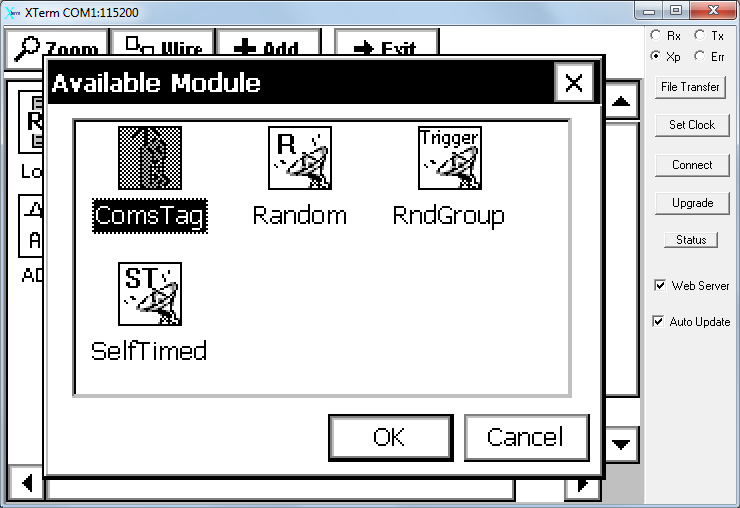
- Add a ComsTag Block.
- Click Add again, then click Telemetry. Select ComsTag and then click OK.
- Note: The ComsTag block is optional. However, if you would like your data to be recorded to the LI-7550 for subsequent analysis in EddyPro, you will need to add the ComsTag and configure it as described below. See Logging for EddyPro.
- Configure the ComsTag Block.
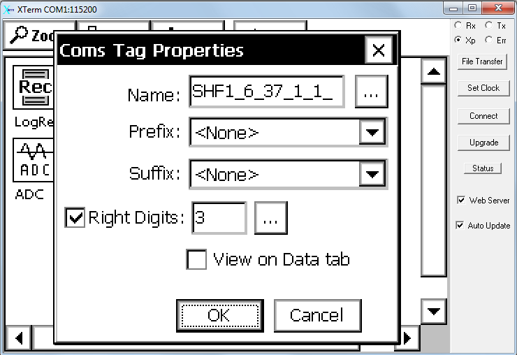
- In order for the LI-7550 version 6 and above (and consequently EddyPro) to interpret the data file correctly, each variable must be given a name in the ComsTag block and your entry into the Name field must meet the criteria described below. To configure the ComsTag block, click it and select Edit Properties.
-
- Name: Enter the name (any name you prefer, UPPERCASE only) followed by an underscore, unit identifier, underscore, variable identifier, and position information, as in the following example.
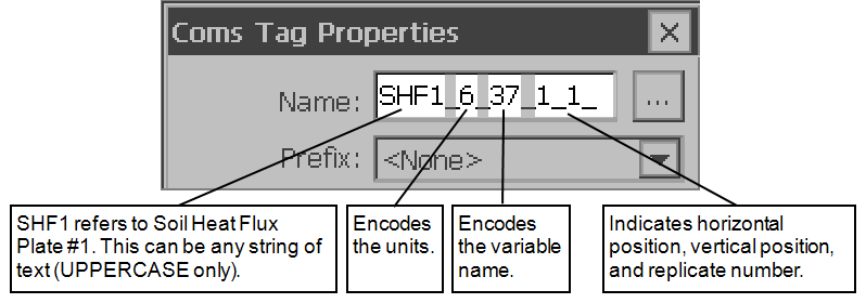
SHF1 refers to soil heat flux plate #1, 6 indicates that the units are W/m^2 (see Table 4‑1), and 37 indicates that the sensor is a soil heat flux plate (see Table 4‑2). The last set of three digits (1_1_1) indicate the horizontal position, vertical position, and replicate number. Both of the numerical identifiers are used by the LI-7550 to define the biomet.metadata file that the LI-7550 creates (and embeds into the .ghg files that will be read by EddyPro). - Prefix: Set to <None>
- Suffix: Set to <None>
- Right Digits: Set to 3 and check the box.
- View on Data tab: Check this box to enable viewing of live data on the Data tab.
- Name: Enter the name (any name you prefer, UPPERCASE only) followed by an underscore, unit identifier, underscore, variable identifier, and position information, as in the following example.
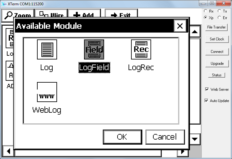
- Add a LogField Block.
- The LogField block is used to specify the name of the variable in the header of the data file, position (column) of the variable in the data file, the number of digits right of the decimal, format of the variable, and the units that are recorded in the header of the logged file. Click Add once again, and then click Logging. Select LogField and click OK.
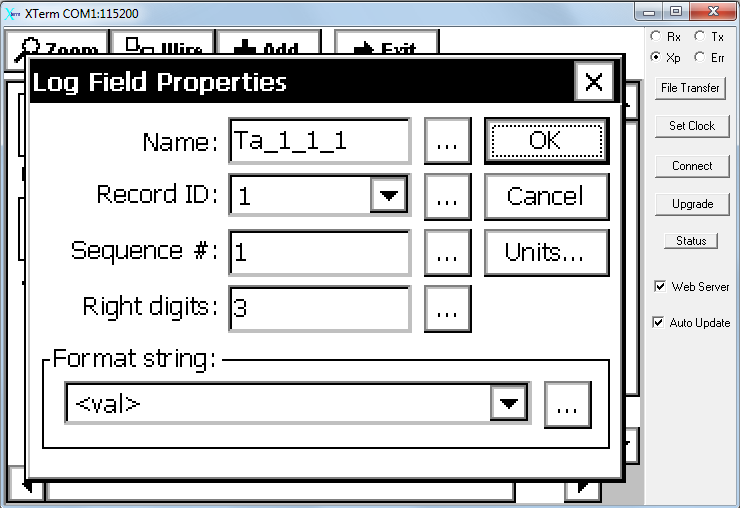
- Configure the LogField Block (Name the Variable).
- Click LogField > Edit Properties to configure the LogField Block:
-
- Name: The name that is recorded in the header of the data file. We have made an effort to standardize default variable names in a manner that is similar to GHG-Europe standards (see VariableID).
- Record ID: The identifier that tells the datalogger that this variable should be associated with the Record ID specified in the LogRec block (see Custom Configurations). It should be the same in both places.
- Sequence #: The column number in the file of logged data.
- Right digits: The number of digits to the right of the decimal (hard stop) for this variable.
- Format string: The data that is output with the variable when the logged data is viewed. Set to <val> for most scenarios.
- Units...: It is possible to set units in other fields, but the units you enter here will be used, overriding any previous entries. We recommend setting the units here.
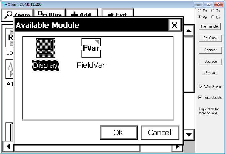
- Add a Display Block.
- Note: This is optional. The procedure described here will allow you to view instantaneous data on the datalogger display.
- Click Add, then click Misc.
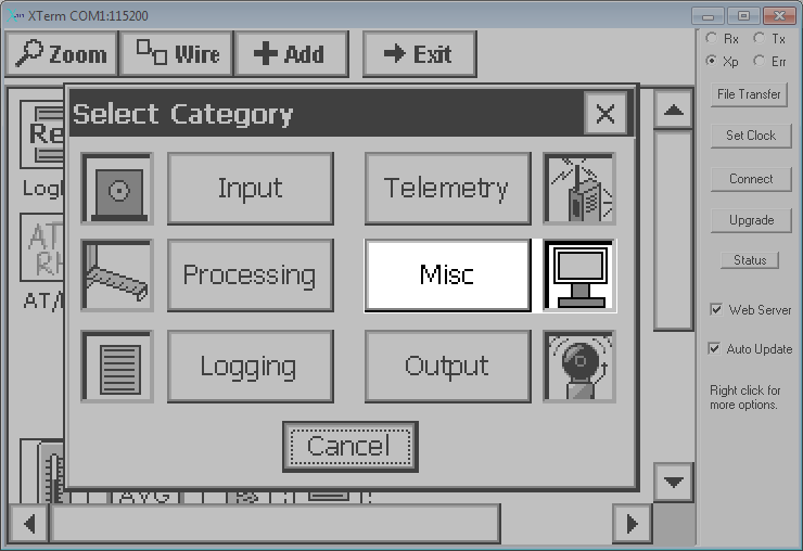
- Select Display, then click OK.
- Click Display > Edit Properties. Enter any desired label and then set the Right Digits to 3.
- Save the Changes.
- After setting up the ADC channel, you will see a series of blocks similar to the image below.
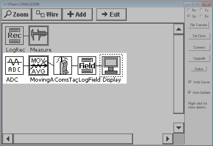
- In order to save the changes to a program, exit the Graphical Setup window and click on any other tab.
- Repeat these steps for each sensor in your system.
IMPORTANT: Save the program or your changes will be lost! To save, exit the Graphical Setup window and click the Main tab or any other tab.
These steps show how to add a Poly block to an ADC channel. The Poly block is used to scale data from sensors that provide non-linear output or to apply a slope or offset to sensor blocks that do not support slope/offset in the standard configuration blocks.
- Add an Input Block.
- For new configurations or to add a sensor to an existing configuration, load the configuration file and add an input block as described in Steps 1 and 2 of the previous section (see ).
- Note: Rename the block however you want for good record keeping. Click on the block and select Rename from the menu.
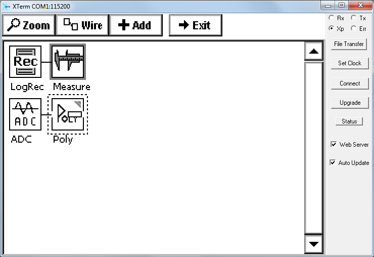
- Add a Poly Block.
- The Poly block applies a polynomial to the analog data provided by the sensor. It goes in between the Input and MovingAverage blocks. Click the Add button, then click Processing. Select the Poly block and click OK.
- Configure the Poly Block.
- The Poly block has 6 fields so you can apply a polynomial to the data up to a fifth-order. To configure it, simply click on it and select Edit Properties. Enter the required values and click OK.
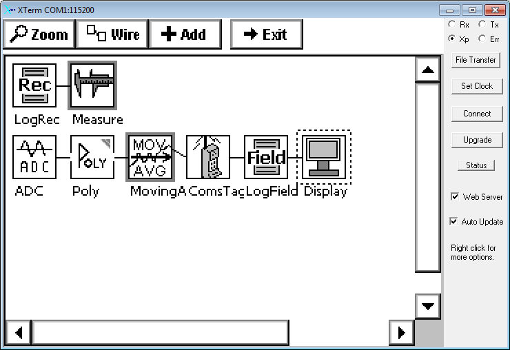
- Proceed to add the MovingAvg, ComsTag, and LogField blocks, after which you should see a series of blocks similar to those in the image below. Now you are ready to configure the channel according to the steps described in the previous section (see Configure the ADC Block.).
IMPORTANT: Save the program or your changes will be lost! To save, exit the Graphical Setup window and click the Main tab or any other tab.
These steps show how to add a tipping bucket rain gauge.
- Add a Counter Block.
- For new configurations or to add a sensor to an existing configuration, load the configuration file and enter Graphical Setup (click Graphical Setup > Edit).
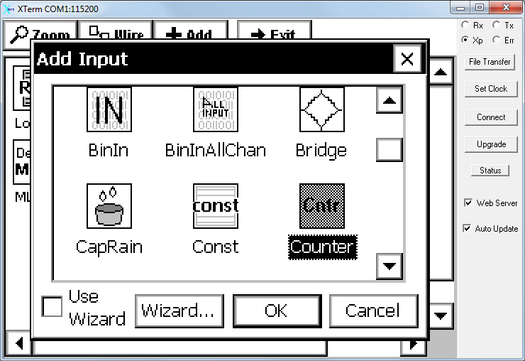
- Click the Add button, then click Input.
-
- In the resulting dialog, select the Counter block and click OK.
- Configure the Pulse Counting Channel.
- After adding all the necessary blocks, click on the Counter block and select Edit Properties.
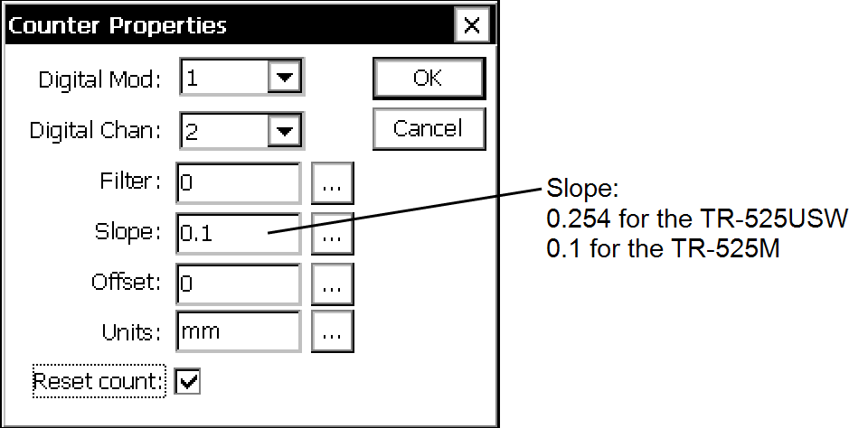
- Configure the following:
-
- Digital Mod: Select the Digital Module. The digital terminal strip on the datalogger is designated as DIO1. If you added digital modules, they are numbered according to your assignment.
- Digital Channel: Select the channel on the digital module that will record the data. Channels are labeled I/O 1, I/O 2, etc. on the terminal strip.
- Filter: This can be set to reduce errant bounces of the switch, or to debounce noisy inputs. A value between 1 and 255 requires the input to last a duration of (value*0.2 ms) before the logger will register the count. For example, set this value to 2 and the logger will only register counts when the switch remains activated for >0.4 ms. Two activations in the 0.4 ms time span will result in a record of a single count. Refer to the 9210B datalogger instructions for more details.
- Slope: In the example, the slope of 0.254 converts the English units (for the Texas Electronics TR-525USW) to metric. For the TR-525M, which measures in metric units, set the slope to 0.1.
- Offset: If the sensor requires an offset from 0.
- Units: The units that are recorded in the header of the data file.
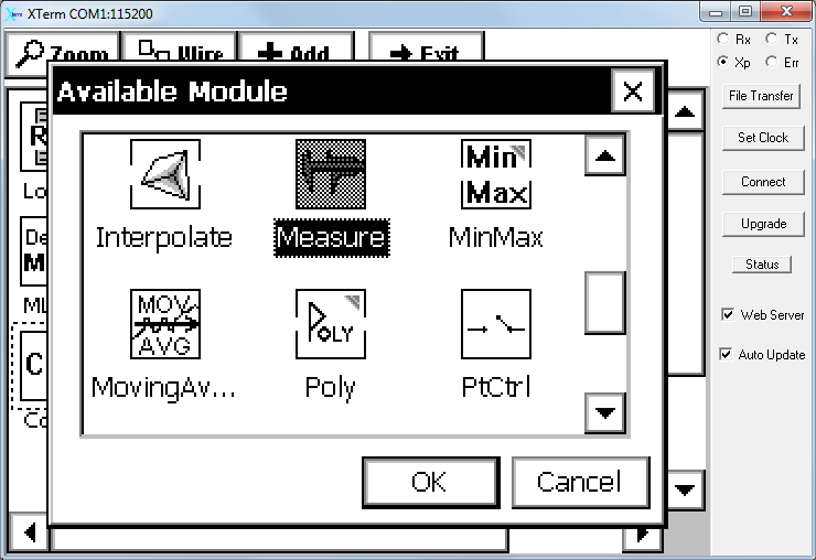
- Add a Measure Block.
- Click the Add button, then click Processing. Select Measure and then click OK.
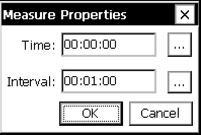
- Configure the Measure Block.
- The Measure block is used to set on offset (Time) and the interval at which the logger will record the number of tips (Interval). An interval of 00:01:00 will result in total number of tips recorded every minute.
- Add and Configure a ComsTag Block.
- Click Add again, then click Telemetry. Select ComsTag and then click OK. See Configure the ComsTag Block..
- Add and Configure a LogField Block.
- Click Add again, and then click Logging. Select LogField and then click OK. See Configure the LogField Block (Name the Variable).. After adding all the required blocks you will see a series of blocks similar to the image below:
- Save the Changes.
In order to save the changes to a program, exit the Graphical Setup window and click on any other tab.
IMPORTANT: Save the program or your changes will be lost! To save, exit the Graphical Setup window and click the Main tab or any other tab.
Multichannel sensors, such as the HMP155 Temperature and Humidity Probe or CNR4 Net Radiometer provide multiple data channels. The process of setting up a multichannel sensor is similar to that for a single channel sensor, except that the input block will have multiple "outputs."
Note: Click the Zoom button on the Graphical Setup window to see the outputs for a sensor.
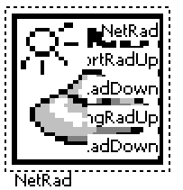
In this example, we added a NetRad block and selected CNR4 under Edit Properties. It has 5 outputs: NetRad, ShortRadUp, ShortRadDown, LongRadUp, and LongRadDown.
- Click on the block, then click on Select Output.
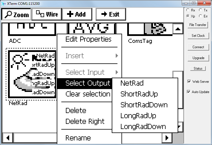
- Select each output separately and configure.
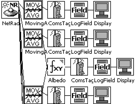
- Configure the first output by adding a MovingAverage block, ComsTag block, LogField block, and Display block, similar to the configuration of a single channel sensor (see Linear Single-Channel Sensor). After the first output is configured, click on the NetRad block again and configure the next output. Repeat until all the outputs are configured. The display should look like this (only first two outputs are shown):
IMPORTANT: Save the program or your changes will be lost! To save, exit the Graphical Setup window and click the Main tab or any other tab.