Self-Calibrating Soil Heat Flux Plates—Hukseflux HFP01SC
Hukseflux HFP01 soil heat flux plates measure heat exchange across the plane of the plate and provide analog data to the Sutron 9210B datalogger. Here we provide basic installation and operation guidelines for using the HFP01 in LI-COR eddy covariance systems running Biomet_102 and Biomet_103. Refer to the manufacturer's operating instructions for more information:
http://www.hukseflux.com/products/heatFlux/hfp01sc.html
| HFP01SC Specifications: | |
|---|---|
| Nominal Sensitivity | 67 μv/W/m2 |
| Typical Range: | -100 to 300 W/m2 |
| Nominal Sensor Resistance: | 2 ohm |
| Nominal Heater Resistance: | 100 ohm |
| Operating Temperature: | -30 to +70 °C |
| Power Consumption (during calibration): | 1.3 W (108 mA @12 VDC) |
| Measurement Range: | ±2000 W/m2 |
| Expected Accuracy: | ±3% |
| Thermal Conductivity: | 0.8 W/mK |
| Sensor Signal Range: | ±5 mV for the above range |
| Heater Signal Range: | 0 to 2 V (while powered) |
Installing Self-Calibrating Heat Flux Plates
Some assembly is required to use self-calibrating heat flux plates in the biomet station. Locate the following components from the Biomet Station Spares Kit:
- Blue Wire Lead; 20 gauge (1)
- Red Wire Leads (3)
- Connect the HFP01SC Heater Relay Leads.
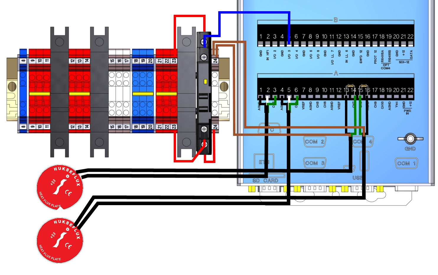
- Install the blue wire lead between the relay terminal 4/A2 and datalogger terminal B5. Install the red relay actuation power wire between the relay terminal +3/A1 and DIN terminal 23. Install the heat flux plate power wire between DIN terminal 23 and relay +1/L1, as shown in Figure 2‑4.
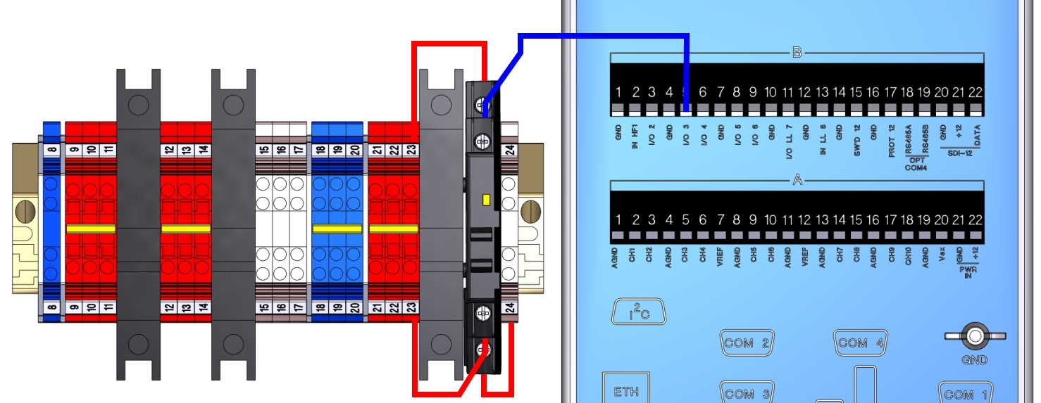
- Figure 2‑4. Relay actuation signal wire and power wire installation.
-
Table 6. Wire lead connections for the calibrating soil heat flux plates. Description Wire Lead Terminals Connected Relay Signal Blue DIO1 Terminal 5(I/O 3) to Relay 4/A2 Relay Power Red DIN Terminal 23 to Relay +3/A1 Heater Power Red DIN Terminal 23 to Relay +1/L1 Heater Power Red DIN Terminal 24 to 2/T1 - Install HFP01SC #1 wire leads.
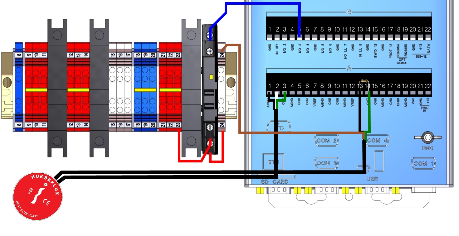
 Note: Route the sensor cable(s) through an opening in the enclosure prior to installing the leads in the terminal strip.
| Description | Sensor Cables | Connection |
|---|---|---|
| Data Cable Shield | Black | AIO1 Terminal 1 (AGND) |
| Data Cable Signal (+) | White | AIO1 Terminal 2 (CH1) |
| Data Cable Signal (-) | Green | AIO1 Terminal 3 (CH2) |
| Description | Sensor Cables | Connection |
|---|---|---|
| Heater Signal | Green | A14 (CH7) |
| Heater Power | Brown | DIN Terminal 24 |
| Heater Ground | Black | A13 (GND) |
| 10 ohm Resistor |
|
A14 (CH7) to A13 (GND) |
- Install HFP01SC #2 wire leads.
| Description | Sensor Cables | Connections |
|---|---|---|
| Data Cable Shield | Black | AIO1 Terminal 4 (AGND) |
| Data Cable Signal (+) | White | AIO1 Terminal 5 (CH3) |
| Data Cable Signal (-) | Green | AIO1 Terminal 6 (CH4) |
| Description | Sensor Cables | Connections |
|---|---|---|
| Heater Signal | Green | A15 (CH8) |
| Heater Power | Brown | DIN Terminal 24 |
| Heater Ground | Black | A16 (GND) |
| 10 ohm Resistor |
|
A15 (CH8) to A16 (GND) |
- Install HFP01SC #3 wire leads.
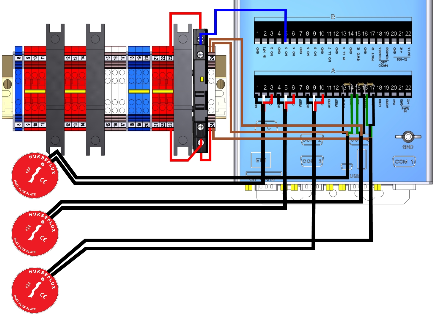
| Description | Sensor Cables | Connections |
|---|---|---|
| Data Cable Shield | Black | AIO1 Terminal 8 (AGND) |
| Data Cable Signal (+) | White | AIO1 Terminal 9 (CH5) |
| Data Cable Signal (-) | Green | AIO1 Terminal 10 (CH6) |
| Description | Sensor Cables | Connections |
|---|---|---|
| Heater Signal | Green | A17 (CH9) |
| Heater Power | Brown | DIN Terminal 24 |
| Heater Ground | Black | A16 (GND) |
| 10 ohm Resistor |
|
A17 (CH9) to A16 (GND) |
Configure the Self-Calibrating Heat Flux Plates
Self-calibrating heat flux plates are supported by program Biomet_102 and Biomet_103. To configure the self-calibrating heaters, connect the Sutron as described in Configuring the Biomet System, then follow the steps below.
- Enter the Calibration Data.
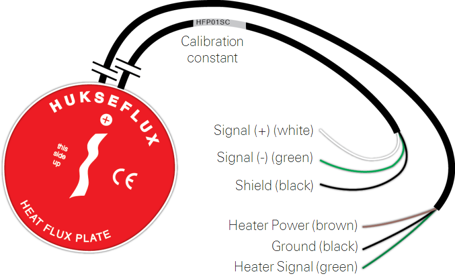
- Each self-calibrating soil heat flux plate includes a unique calibration constant that is provided by Hukseflux. It is printed on the sensor cable label in units of μV/W m‑2. The calibration constant should be entered directly into the datalogger software.
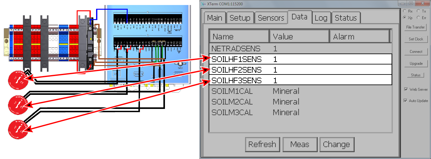
- Click the Data tab, select the soil heat flux plate (e.g., SOILHF1), then click Change.
- Enter the sensitivity from the cable label.
- In this example, the sensitivity is 60.7 μV/W m-2.
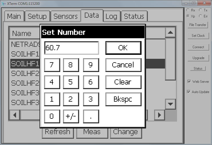
- Enter the value and click OK.
- Repeat this for the remaining soil heat flux plates.
- Note: You can edit the Heat Flux Plate Rself value here by changing the SOILHF#RSELF field. This entry is the same Rself.
- Only one setting must be configured—the Rself value—the self resistance of each self-calibrating heat flux plate. It can be found on the sensor calibration certificate. Enter these values for each HFP01SC.
- The figure below shows which sensors are associated with each name in the program.
- If desired, alter the calibration timing settings.
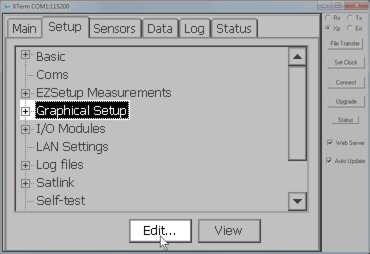
- Under the Setup tab, select Graphical Setup and Click Edit.
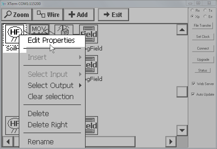
- Scroll down the graphical setup window until the first Soil Heat Flux Plates block (Soil HF) is visible.
- Left-click the block and click Edit Properties.
- Click the Cal... button.
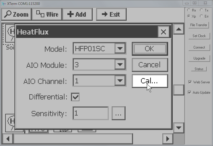
- Enter the desired values:
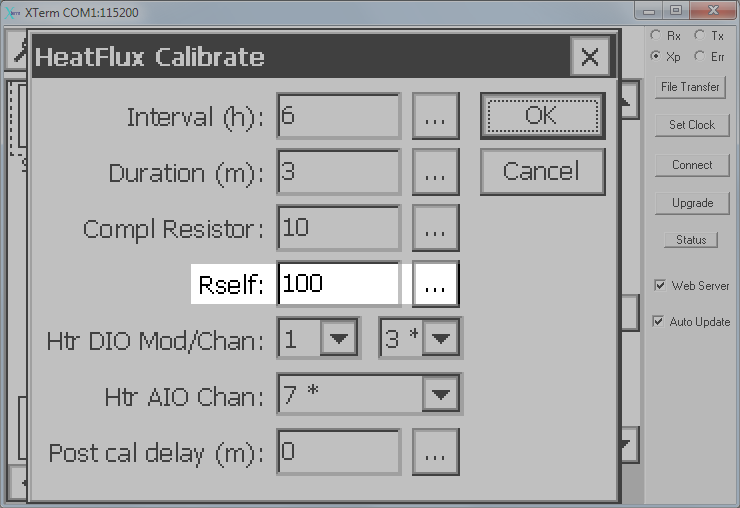
- Interval (h): Time between self-calibrations. Default is 6 hours.
- Duration (m): Time span of active heating. Default is 3 minutes.
- Compl Resistor: Resistance of the resistor (ohms). LI-COR provides a 10.0 ohm resistor.
- Rself: Resistance of the heat flux plate (from the manufacturer's data sheet). There is a specific value for each sensor. This can also be changed in the Data tab.
- Htr DIO Mod/Chan: Digital module # (1 in the default programs) and channel.
- Htr AIO Chan: AIO module channel for the heater voltage (channels 7, 8, & 9).
- Post cal delay (m)1: Number of minutes to extend the calibration cool-down period. Default is 0 minutes.
Configure the timing of each HFP01SC and click OK and Exit and close the open dialog boxes. The program is saved and updated when you click on another tab.
Retrieving Data
If the system is configured to log biomet data in .ghg files for processing in EddyPro software or the SmartFlux System, data are stored on the removable USB storage device. Refer to the Biomet Instruction Manual for details.
Maintenance
- Check the devices regularly by observing the data they provide.
- Periodically check the wire leads for rodent damage.
- Recalibrate the sensors every two years according to the manufacturer's instructions.
Wiring Diagram
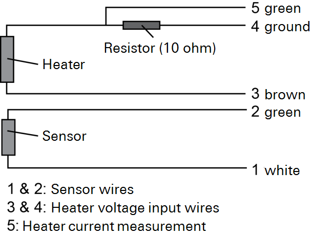
The enclosure includes connections, resistors, and wire leads for three self-calibrating heat flux plates. If you want to add more than three self-calibrating heat flux plates to the biomet station, the required modular terminals and resistors can be purchased directly from LI-COR. Contact us for more information.