This section describes the physical characteristics of the instrument, the keypad interface, basic software navigation, initial setup, and instrument care.
Control Unit
The control unit (console) houseing is constructed of durable ABS plastic with a rubber seal between the two halves. The rubber seal also serves as a shock cushion to protect the instrument from impacts.
Display
The display is a 128 x 64 LCD graphics display. It shows alphanumeric characters. To adjust the display contrast hold the minus (-) key and press the up or down arrow keys.
Keypad
The LAI-2200C features a 22-button tactile response keypad. The upper block of 9 keys are used to navigate through menus, select menu options, and log data. Basic functions of the upper 9 keys are described in the following chart:

|
Press Menu to go to the Main Menu; or when in Logging Mode, to go to the Log Adjust menu. |

|
Exit returns to the main screen unless an input or toggle field is active. In these cases it returns to the previous screen. |

|
OK selects the highlighted menu field or implements a setting after changes have been made. |

|
Start/Stop is used to initiate or terminate a logging sequence. |

|
When in Log mode, the Log button records a reading (or two if two wands are attached). |

|
The Up arrow and Down arrow buttons are used to navigate through menu options and increment or decrement values in some fields. |

|
The Right arrow and Left arrow buttons advance to the next or previous menu sub-level when on a menu screen. If a toggle field is active they toggle the setting. They also are space and backspace keys in alphanumeric fields. |
The lower block of 12 keys are used to enter alphanumeric characters. Each key is used to enter the letters and numbers indicated by the label on the key. Keys 1–9 can also be used to log global positioning system (GPS) coordinates when GPS is active and a file is open in the LAI-2200C (or LAI‑2200 equipped with GPS). The 22nd key is the power on/off key at the top left of the keypad.
When entering alphanumeric characters with the keypad, each button cycles through a loop of characters and stops looping when a different button is pressed or after 1 second has passed without a button press. Some fields can only accept numeric or alphabetic characters. The right arrow key is used to enter spaces and the left arrow key functions as a backspace key in alphanumeric fields.
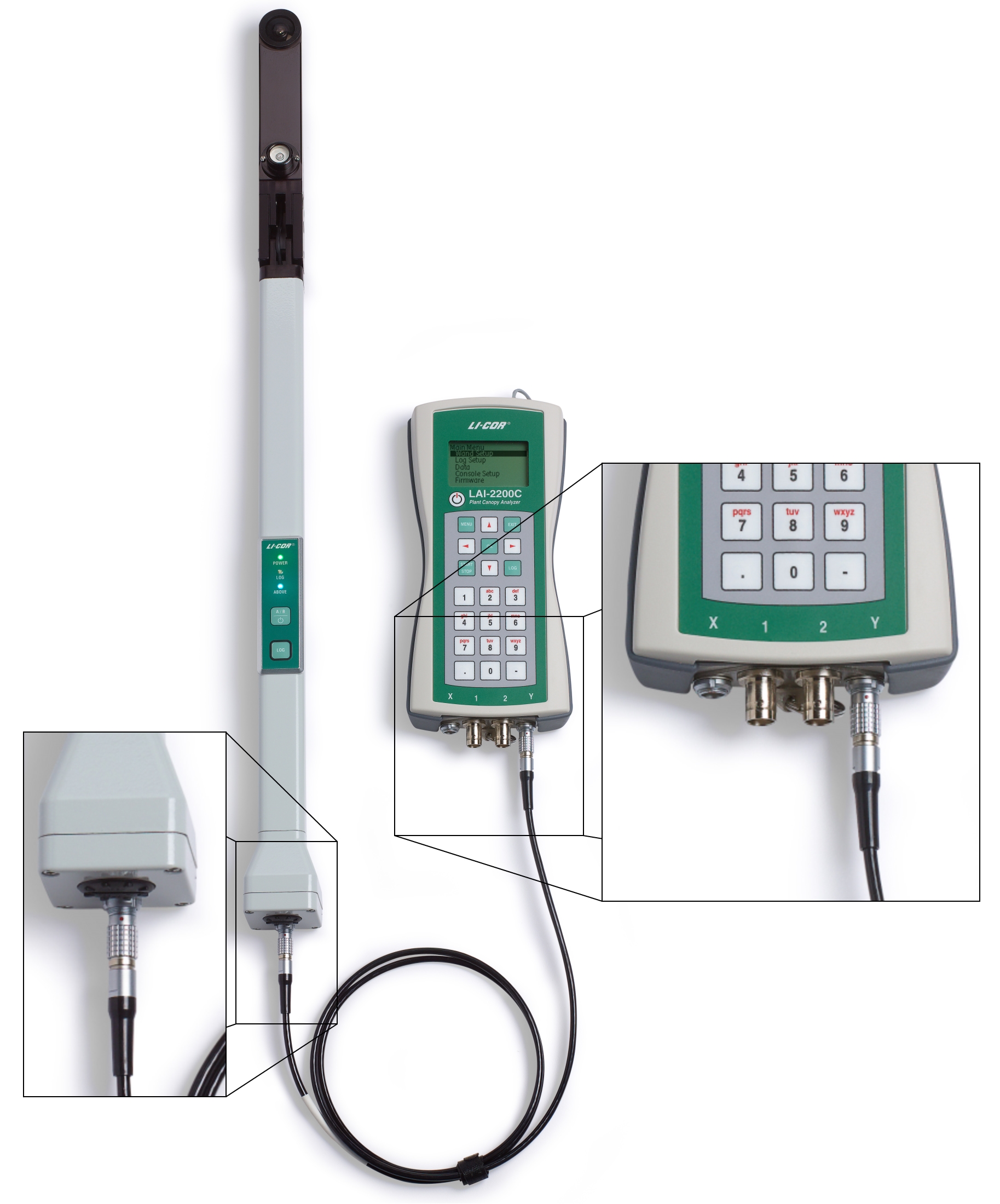
Cable Connections
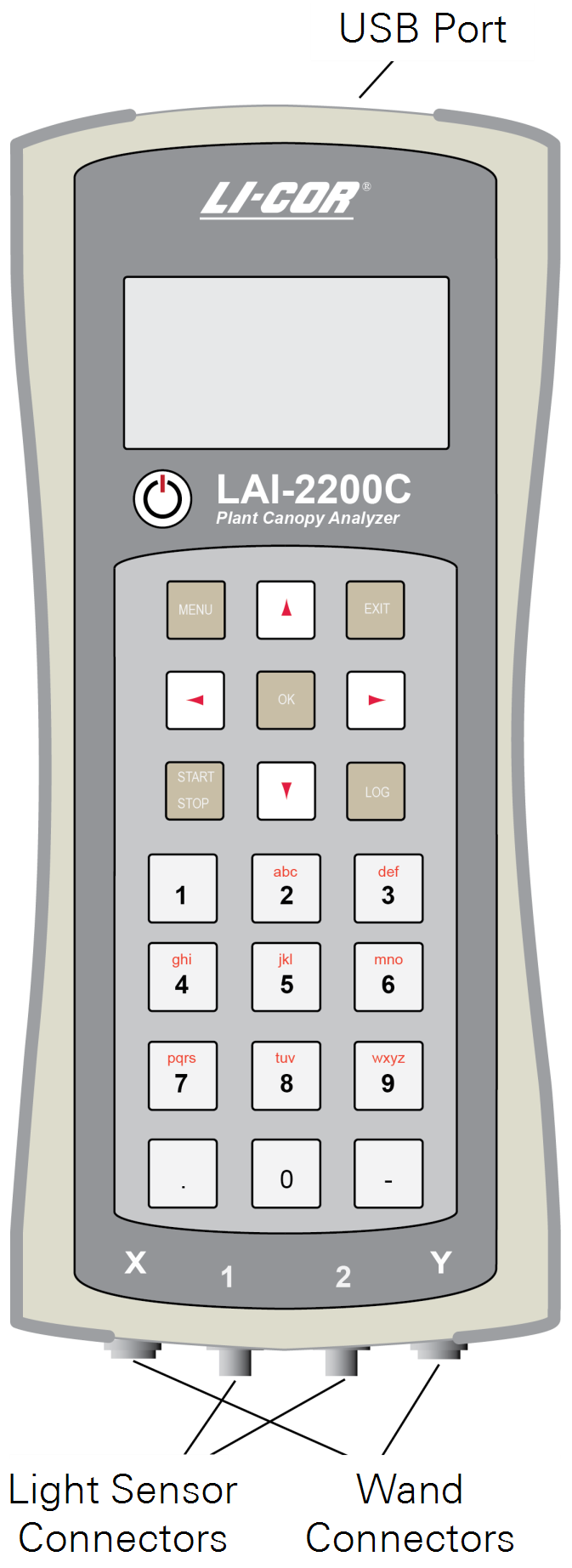
USB (Universal Serial Bus), light sensor, and optical sensor connections are on the top and bottom of the LAI-2200C console.
Optical Sensor Cable Connections
The 6-pin bulkhead connectors (labeled X and Y) are used to attach optical sensors (wands). The control unit will automatically detect an attached wand. Wands can be attached or removed while the instrument is powered on. To attach the cable, orient the red dot on the cable toward the keypad and press straight in. To release the cable, grasp the collar and pull straight out.
Light Sensor Cable Connections
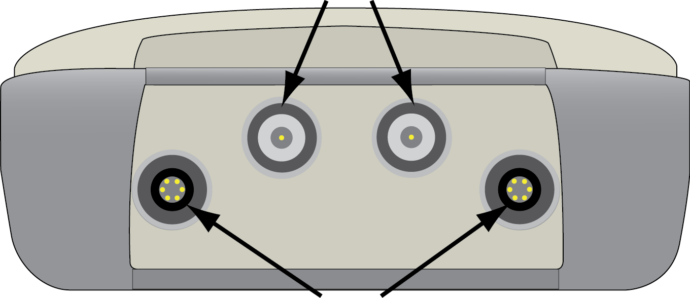
Two BNC (Bayonet-Neill-Concelman) bulkhead connectors are available to attach LI-COR Quantum Sensors. They are labeled “1” and “2” on the front of the control unit and identified as Port 1 and Port 2 by the control unit.
| BNC Light Sensor Connectors |
|
| LAI‑2250 Optical Sensor (wand) connectors X and Y |
Data Cable Connection
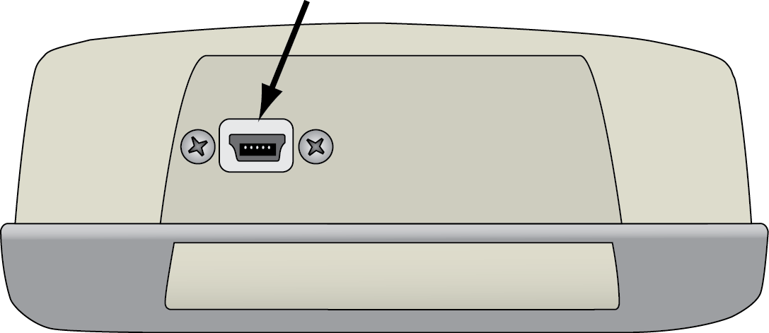
A Mini USB port is available for communicating with a computer (Connecting to a Computer). When connected with a USB cable, the computer will identify the LAI‑2270C (the control unit) as a mass storage device.
| Mini USB Port |
|
Memory
The control unit is equipped with 128 MB of non-volatile flash memory. The instrument stores data on an internal Secure Digital (SD) card, which should provide sufficient memory for intensive data collection (enough storage for over 1.5 million records).
The format for the SD card is FAT16. Do not modify the card in any way when connected to a computer, and never remove or replace the card unless it is with a card purchased from LI-COR Environmental (part number 616-10387).
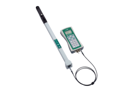
Optical Sensor
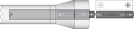
The optical sensor (wand) is constructed with a durable aluminum enclosure, which protects the electronic and optical components. It can be mounted to a camera tripod or raising pole using one of the ¼”-20 tripod mounting holes. It can be used independently of the control unit for data collection. When the wand is attached to a console, it is powered with the console batteries – it does not require its own batteries. Otherwise, it requires two “AA” batteries.
 Caution: Batteries must be inserted with the positive poles (+) toward the cap.
Keypad
The optical sensor keypad includes two buttons that are used to log data, switch between A and B readings, and power on/off the optical sensor. The LOG button on the wand functions the same as the log button on the console – if the console is in logging mode (see Logging Mode), the LOG button will log a record to the open file.
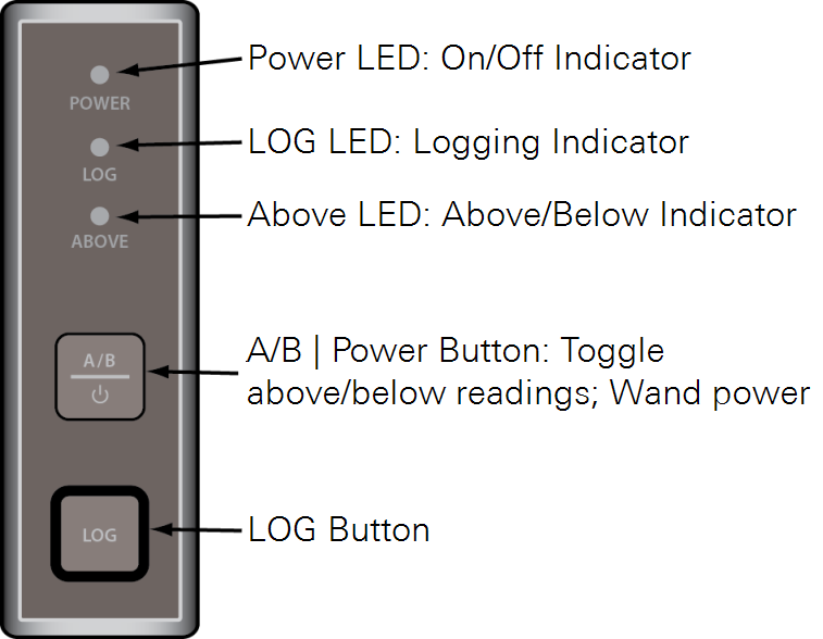
Optical sensors will turn on when the control unit is turned on (if the wand and control unit are attached), when the optical sensor cable is connected to a powered-on control unit, or when the optical sensor power button is pressed (when disconnected from the control unit). To turn the optical sensor off, press and hold the A/B|Power button for 2 seconds. To switch between A and B readings press and release the A/B|Power button.
Indicator LEDs
Three light emitting diodes (LED) indicate the state of the optical sensor. The POWER LED is illuminated when the sensor is turned on. The LOG LED illuminates when data are being recorded. When the LOG button is pressed, the LOG LED lights up for the duration of the reading and turns off when the log is complete. The optical sensor’s LOG LED will flash every 2.5 seconds or 1 second as part of automatic, unattached logging (see Support: LAI-2200C Plant Canopy Analyzer). The ABOVE LED indicates whether the next reading from this sensor will be labeled A (LED is on) or B (LED is off). Pressing the A/B|Power button switches between A and B readings.
Features
The optical sensor has 1 megabyte (MB) non-volatile flash memory that is used when operated in unattached mode (for about 25,000 records). The optical sensor will indicate that its memory is full by flashing all three LEDs simultaneously. When the optical sensor batteries are low (<2V), the green POWER LED will turn red. The optical sensor will shut off automatically when the battery voltage is below 1.8 V.
Optical sensors do not require batteries when they are used in attached mode - they use power from the control unit. Be aware, however, that if a data cable is removed during a data transfer between the wand and console, the files may be damaged or lost. The control unit display indicates when data transfer is taking place with an on-screen indicator (see Logging Mode). Be sure to wait until data transfer is complete before disconnecting the data cable.