Overview of Configurations
The settings described in Wand Setup affect the selected wand and are stored on the wand. Those described in Log Setup affect the global template and will be applied to any new file that is created on the control unit. Settings that affect how LAI is computed are stored as part of each file. The procedure for changing the settings of a file (post processing data) is described for the console in Data Management on the Console or with FV2200 in chapter Data Analysis with FV2200.
Wand Setup
Certain pieces of information are stored on each optical sensor. You may wish to change or view these settings. They are described below. In order to access these settings, one or more wands must be connected, and you must select a wand.
Set Name: You can name each wand (up to 8 alphanumeric characters). The name is stored on the wand and can be viewed when the wand is connected to a console.
Clock: Set the wand time by synchronizing with the console clock or entering the time manually.
Cal Values: View/Edit the five back-up calibration values. These values are shown on the wand’s calibration sheet.
Match Values: Access the five working cal values: view/set values to directly edit or reset them, and calculate values for matching two wands.
Auto Log: The control panel for setting up automatic logging for wand.
Log Setup
Basic parameters can be set prior to collecting data. For most applications the default settings will work fine, but the preferred settings will vary depending on the application. Most of the following settings can be changed for a file after data has been collected as well. The following items are in the Main Menu > Log Setup menu:
Transcomp: Defines how transmittance is computed (including which readings (A or B) are used for above-canopy readings, how they are used, and what the instrument does with transmittances >1.0). These settings are described in detail in the table below. Normally, A readings are above canopy, and B readings are below. The software can also be set to determine which is above and which is below by comparing the readings (ring by ring) of successive A/B pairs or records until it finds a pair for which every ring of one is consistently higher than the corresponding ring of the other. The ID of the higher record, whether A or B, is assumed to be the above record ID through the rest of the file.
| Transcomp Setting | Description |
|---|---|
| Define Above | |
| A | (Default) A records are Above, B are Below |
| B | B records are Above, A are Below |
| Compare | Find which is Above and which is Below |
| Determine Above | |
| Previous | (Default) Use the previous Above record |
| Interpolate | Interpolate between the nearest (time) Above readings |
| Closest | Use the closest in time Above record |
| Bad Readings (when a Below record has values that exceed those of a corresponding Above record) | |
| Skip | (Default) Skip that record |
| Clip | Force the transmittance (Below/Above) to be 1.0 for that ring |
Prompts: Two prompts can be defined, and responses can be entered during data collection for each file.
Obs Remarks: An observation remark can be entered for each data record. This remark is edited in the log setup menu, and can be changed for individual records by pressing the Menu key while in Logging Mode.
Angles: This provides access to the angle values associated with each ring. There is no need to change these values.
Distances: The distance vector consists of five values used in calculation of contact numbers for the five rings of the optical sensor. Use the default values unless you are measuring an isolated crown of a plant. Refer toThe DISTS Vector for more information.
Masks: The mask determines which rings are used (default = all) to compute LAI. Data from rings that are ignored are still measured and recorded, however, so nothing is lost even if a data file is generated with all rings ignored.
Controlled Sequence: A sequence of A and B readings can be defined.
Console AutoLog: Activate and set up automatic logging with wand(s) attached to the console.
PAR Sensors: Activate, name, and enter the calibration multipliers for LI-COR Light Sensors here.
GPS: Activate the global positioning system and choose settings for when GPS data are recorded.
Console Setup
The Console Setup menu (Main Menu > Console Setup) provides some basic setup options:
Set Time: Set the instrument time, as described in Setting the Clock.
Auto Off Timer: Set the duration that the control unit will remain powered on after no buttons have been pressed (5-60 minutes, increments of 5 minutes).
Beeper: Turns the console beeper on or off.
Attached vs. Autonomous Configuration
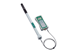
In this section you'll find an overview of the ways that you can use the wand to collect data: attached to the console or autonomously (detached from the console).
Attached Configuration
This is the configuration used when an optical sensor is attached to the control unit. The main advantage of having the sensor attached to the console is real-time display of measured or computed values. When in log mode, pressing the wand or console LOG button adds data to the file on the console, not the wand, and LAI calculations are updated for that file. In the console autolog configuration, logging occurs at set intervals without pressing the LOG button (see Logging Configurations).
Autonomous Configuration
This is useful for logging above canopy readings well away from the console, for later import to the console. Data can be logged manually (press LOG) or automatically (Logging Configurations) on an unattached wand, and later transferred to the console and merged with below-canopy readings. Note that you can also use a wand by itself to make complete one-sensor readings of a canopy: Just label above and below readings appropriately using the A/B button, transfer the result to a file, and recompute that file. However, since records stored on a wand accumulate in one big file, this method is not convenient for generating multiple LAI files, unless you keep careful track of starting and stopping times, so you'll know how to parse the file later.
Operating Modes: One and Two Sensor Modes
You can collect data with one or two wands, as described below.
One Sensor Mode
The simplest operating mode is to use one sensor for above and below readings. A sequence of readings can be predefined if attached to a console (see Support: LAI-2200C Plant Canopy Analyzer), or determined “on-the-fly” by using the A/B key on the wand keypad. The basic procedure for using this mode is described in Operation: One Sensor, One Control Unit.
Two Sensor Mode
Two-sensor mode simply means that there are two (or more) sensors involved in collecting data. There are some possible combinations here:
- One sensor detached. This is the usual configuration. The detached sensor can stay in an adequate clearing and automatically log above canopy records. Later, the logged readings are transferred to a file in the control unit, and selected records (those closest in time to the recorded below canopy records) will need to be imported from there to the below canopy files.
- Both sensors attached to a control unit. This configuration has limited usefulness, since the sensors can’t be very far apart. However, in a short canopy with very changeable sky conditions, this can be a reasonable approach, provided there is an extra person (or a tripod) to hold the above sensor. This method does put both A and B records in the same file, so later import is not needed.
-
Matching Sensors
When using two or more optical sensors, they need to be matched so that they read the same thing under the same conditions. This can be done by console matching or FV2200 matching. The recommended method is FV2200 matching. This involves collecting data from both sensors that can later be used to adjust one set of readings in post processing using the FV2200 Software package. There are multiple ways to do this, and they are discussed in Multiple-Sensor Operation Revisited.
Console matching, desribed in Procedure 2.1 - Making Two Wands Match - Console Matching, is the required method when both optical sensors are attached to the console while logging (only possible with short canopies). Console matching cannot be used with light scattering correction.
Setting Prompts
There are two prompts for storing additional information with each data file. Each prompt can be defined so that it requests a specific type of information, such as “What” and “Where”. For the “What” prompt, you might enter a habitat type, and for the “Where” prompt, you could enter the location. After they are defined, you can enter up to 8 alphanumeric characters in each of the prompt fields when you create a new data file. To set prompts:
- Press the Menu button, then go to Log Setup and select Prompt.
- Enter the desired prompts in the Prompt1 and Prompt2 fields. If you wish, you can enter default responses, or leave the Resp1 and Resp2 fields blank. Either way, you will be able to enter responses in the Resp1 and Resp2 fields when you create a new data file.
Creating Data Files
An LAI measurement is made by collecting above and below readings in a file. Follow the steps below to create a new file:
- With the instrument on, press the START|STOP button.
- Select New File and enter a file name (a maximum of 8 characters or numbers). File names are automatically generated based on the previous entry, incremented by one digit.
- View/Edit Prompts, and/or press OK.
- The LAI-2200C is now in Logging Mode (below). Log A and B readings.
- Press START|STOP (or EXIT) to save the file and quit.
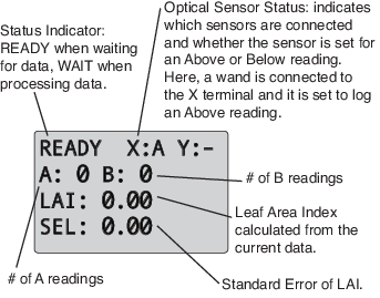
Logging Mode
After a new file is created (see above), the console will enter Logging Mode, which is used to log data to the open file. In Logging Mode, the display will show four lines of data. The Status indicator line is always displayed, along with three of the following fields:
| Field | Description |
|---|---|
| A:#B:# | # A readings, # B readings |
| T: | Time (HH:MM:SS) |
| D: | Date (YYYY/MM/DD) |
| BATT | Battery Voltage |
| 1 or 2 | Readings for Light Sensor 1 or 2 |
| X1,...,X5 | Readings for Wand X, rings 1-5 |
| Y1,...,Y5 | Readings for Wand Y, rings 1-5 |
| gLAT: | Latitude |
| gLNG: | Longitude |
| gALT: | Altitude |
| gSAT: | Number of Satellites used |
| gHDOP: | Horizontal Dilution of Precision |
| gUTC: | UTC time (YYYY/MM/DD, HH:MM:SS) |
| SEQ: | Off or AB (to indicate controlled sequence) |
| LAI: | Current Leaf Area Index |
| SEL: | Standard Error LAI |
| MTA: | Mean Tilt Angle |
| SEM: | Standard Error MTA |
Use the arrow keys to change what is displayed in the other fields. These changes are saved automatically.
You can also enter the “Log Setup” menu from the logging menu (press the MENU key while in Logging Mode). Any changes made here will only be reflected in the current file, except changes to light sensors, which will be retained even after exiting Logging Mode.
Computations During Logging
While logging data, the LAI-2200C provides real time updates of some computed quantities, such as LAI. These computations are always done with a Transcomp setting of “xPx”. That is, the middle setting (Determine Above: Previous, Interpolate, or Closest in time) is always P (Previous), regardless of what you have selected. This is out of necessity, because there is no way to interpolate or choose the closest “Above” reading before all the “Above” readings have been made. When you are done logging and close the file, if the file needs to be recomputed because of this mismatch, (or for other reasons, such as logging to an existing file), you will be prompted with Compute file?. If you respond with OK, the file is recomputed and stored. If you decline the recomputation, the file is stored without being recomputed. It can be recomputed at a later time.